Introduction to REVIT concepts
1. Aim: To create the new project and name the project in the revit soft ware.
- The rivet soft ware is used to develop and design the building model.
- Rivet offers a visual of the 3d model of the building and also add muiltiple detail elements to the project to make it realistic as much as possible.
- In the rivet the design concept and the design standards plays much more important and a key role for the design of the building model.
Procedure:
- Click on the rivet soft ware icon in the PC and open the rivet software.
- Then the screen is displayed with the options such as 'OPEN' and 'NEW' and with the icons of the sample files of the rivet.
- Then click on the NEW option then it ask to select the mode of the project as Construction template or architectural template or structural template or mechanical or electrical or Plumbing then select the architectural template for the building design and a new file is opened with the architetural template
- Now click on the file in the top and change the name of the file as the Challenge 1 and click on the save button.
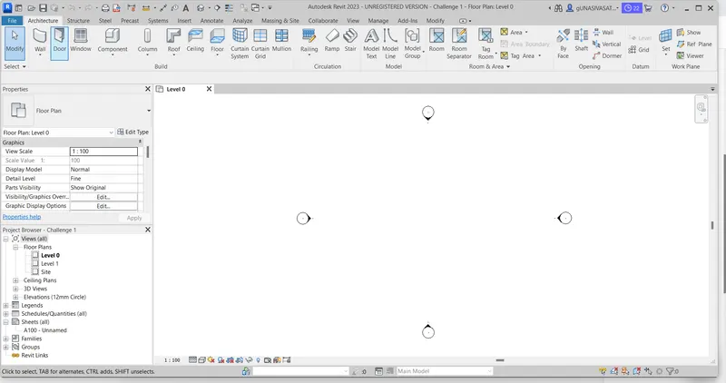
- Then the new project is displayed with the name of the project as Challenge 1.
Result:
- The final file after saving the name of the file as challenge 1 the projcet template is displayed as the Architectural template with the title as Challenge 1.
- The template is now ready to develop the model of teh building in the architectural mode.
2. Aim: To create the new project and open the new project using the icons in the file tool bar.
- The rivet soft ware is used to develop and design the building model.
- Rivet offers a visual of the 3d model of the building and also add muiltiple detail elements to the project to make it realistic as much as possible.
- In the rivet the design concept and the design standards plays much more important and a key role for the design of the building model.
Procedure:
- Click on the rivet soft ware icon in the PC and open the rivet software.
- Then the screen is displayed with the options such as 'OPEN' and 'NEW' and with the icons of the sample files of the rivet.
- Then click on the NEW option then it ask to select the mode of the project as Construction template or architectural template or structural template or mechanical or electrical or Plumbing then select the architectural template for the building design and a new file is opened with the architetural template
- Now click on the file in the top and change the name of the file as the Challenge 1 and click on the save button.
- Then the new project is displayed with the name of the project as Challenge 1.
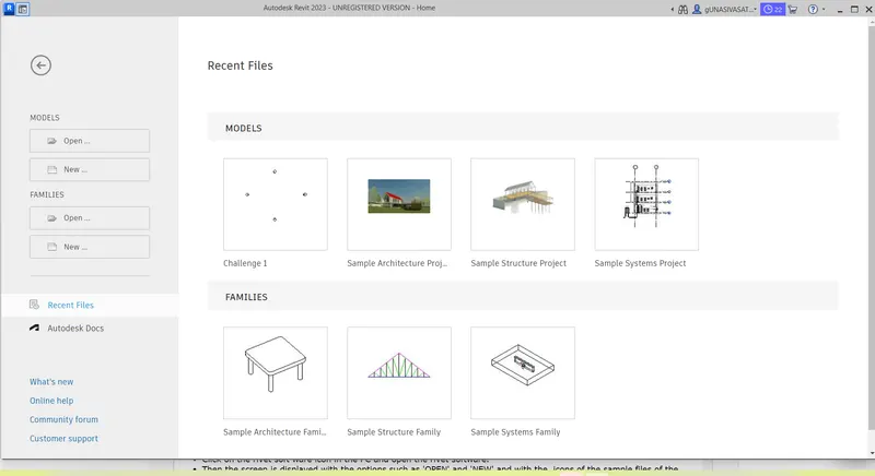
- Then click on the file option and select the close option in the menu and the architectural template is closed and now the File is displayed as a icon on the file tool bar, the file challenge 1 is displayed as a first icon on the file tool bar as it is a recent file.
- Now click on the icon challenge 1 then the file challenge 1 file is opened as a architectural mode is opened as shown below.
Result:
- The files can be opened either by select ting the files in the open option in the file menu or otherwise selecting the icons displayed in the file tool bar, This is fastest and easy method to open the files quickly.
- The icon window of the file tool bar is shown below.
3.Aim: To create the rectangular lay out of the wall with the size 40'x35' in the revit soft ware.
- The rivet soft ware is used to develop and design the building model.
- Rivet offers a visual of the 3d model of the building and also add muiltiple detail elements to the project to make it realistic as much as possible.
- In the rivet the design concept and the design standards plays much more important and a key role for the design of the building model.
- The lay out of a building defines the boundry of the building or the site. The model is developed and designed with in the limits of the layout.
Procedure:
- Click on the rivet soft ware icon in the PC and open the rivet software and create the new project file with the architectural template.Then a new file with the architectural mode is displayed.
- Now select the Architectural option and it will displays the new menu bar with various options like wall,door,Curtain,roof, column etc.
- Now click on the wall option and the wall can be plotted with the various options like line, rectangular, polygonal etc.
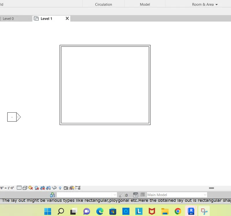
- Now select the line type wall and plot the wall to a size of the 40'x35'.The layout is created as a rectangular shape 40'x35'.
Result:
- The lay out might be various types like rectangular,ploygonal etc.Here the obtained lay out is rectangular shape reembling the length of size 40' and width of size 35'.
- The layout is ready and the building model is developed in the inside of the layout.
- The final layout formed is shown below.
4.Aim: To create the rectangular lay out of the wall with the size 40'x35' and assign the dimension for the layout in the revit soft ware.
- The rivet soft ware is used to develop and design the building model.
- Rivet offers a visual of the 3d model of the building and also add muiltiple detail elements to the project to make it realistic as much as possible.
- In the rivet the design concept and the design standards plays much more important and a key role for the design of the building model.
- The lay out of a building defines the boundry of the building or the site. The model is developed and designed with in the limits of the layout.
Procedure:
- Click on the rivet soft ware icon in the PC and open the rivet software and create the new project file with the architectural template.Then a new file with the architectural mode is displayed.
- Now select the Architectural option and it will displays the new menu bar with various options like wall,door,Curtain,roof, column etc.
- Now click on the wall option and the wall can be plotted with the various options like line, rectangular, polygonal etc.
- Now select the line type wall and plot the wall to a size of the 40'x35'.The layout is created as a rectangular shape 40'x35'.
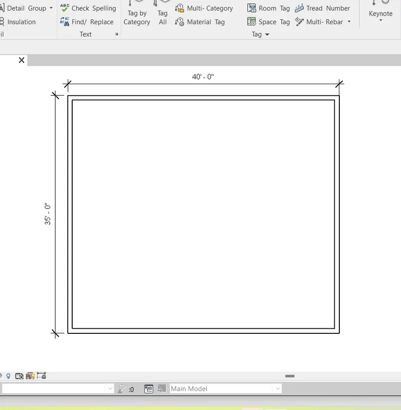
- Now click on the annotate button in the menu bar and select the dimension linear and assign the dimension of the lay out as 40'x35'.
Result:
- The lay out might be various types like rectangular,ploygonal etc.Here the obtained lay out is rectangular shape reembling the length of size 40' and width of size 35'.
- The layout assigned with the dimensions is ready and the building model is developed in the inside of the layout.
- The final layout assigned with dimensions obtained is shown below.
5.Aim: To create the rectangular lay out of the wall with the size 40'x35' and change the wall type using the properties browser for the layout in the revit soft ware.
- The rivet soft ware is used to develop and design the building model.
- Rivet offers a visual of the 3d model of the building and also add muiltiple detail elements to the project to make it realistic as much as possible.
- In the rivet the design concept and the design standards plays much more important and a key role for the design of the building model.
- The lay out of a building defines the boundry of the building or the site. The model is developed and designed with in the limits of the layout.
Procedure:
- Click on the rivet soft ware icon in the PC and open the rivet software and create the new project file with the architectural template.Then a new file with the architectural mode is displayed.
- Now select the Architectural option and it will displays the new menu bar with various options like wall,door,Curtain,roof, column etc.
- Now click on the wall option and the wall can be plotted with the various options like line, rectangular, polygonal etc.
- Now select the line type wall and plot the wall to a size of the 40'x35'.The layout is created as a rectangular shape 40'x35'.
- Now click on the annotate button in the menu bar and select the dimension linear and assign the dimension of the lay out as 40'x35'.
- The properties browser helps to change the wall type or base constraint,top constraint etc for the lay out or for any other model unit in the project.
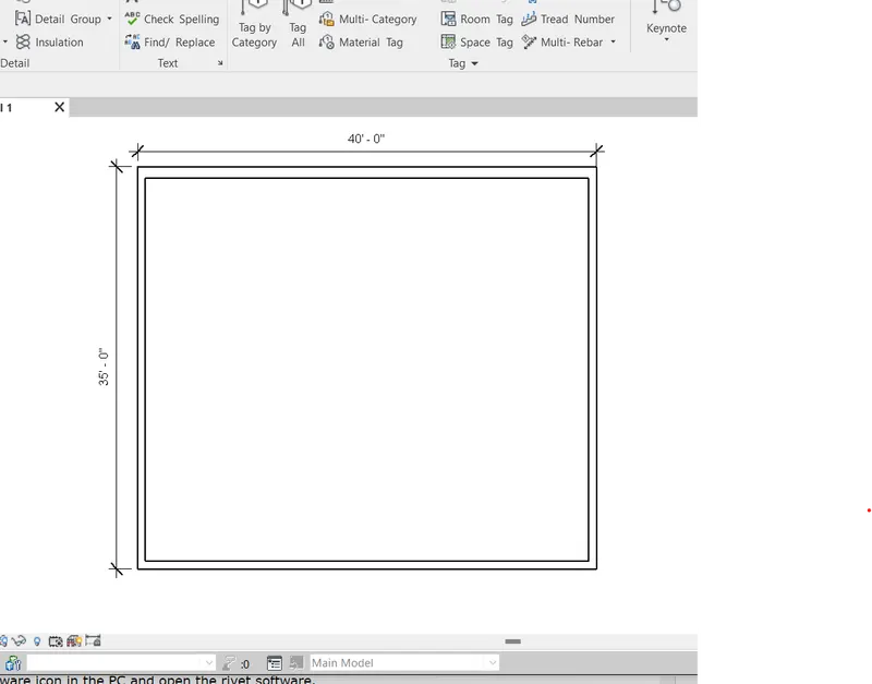
- The formed lay out is rectangular with the wall thickness 8" and the wall thickness is to be changed to 12".Select the wall which is to be changed and select the type of wall with desired thickness i.e 12" in the properties browser and press enter then the wall thickness is changed to the 12"
Result:
- The lay out is now changed with various wall thickness i.e the walls with the 35' length is 8" thickness and the walls with the length 40' are one with the 8" thickess and the other with the 12" thickess.
- The wall base constraint and the top constraint can be changed with properties browser to a required height.
- The final layout with the changed wall thickness with dimensions obtained is shown below.
6.Aim: To create the rectangular lay out of the wall with the size 40'x35' and plot the 3d view of the layout in the revit soft ware.
- The rivet soft ware is used to develop and design the building model.
- Rivet offers a visual of the 3d model of the building and also add muiltiple detail elements to the project to make it realistic as much as possible.
- In the rivet the design concept and the design standards plays much more important and a key role for the design of the building model.
- The lay out of a building defines the boundry of the building or the site. The model is developed and designed with in the limits of the layout.
Procedure:
- Click on the rivet soft ware icon in the PC and open the rivet software and create the new project file with the architectural template.Then a new file with the architectural mode is displayed.
- Now select the Architectural option and it will displays the new menu bar with various options like wall,door,Curtain,roof, column etc.
- Now click on the wall option and the wall can be plotted with the various options like line, rectangular, polygonal etc.
- Now select the line type wall and plot the wall to a size of the 40'x35'.The layout is created as a rectangular shape 40'x35'.
- Now click on the annotate button in the menu bar and select the dimension linear and assign the dimension of the lay out as 40'x35'.
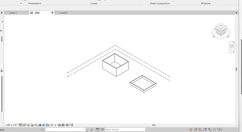
- Now click on the 3d view at the top of the window which will change the 2d view of the layout in to the 3d view of the layout.
- The 3d view can be saved to inthe desired form of the model.The 3d view can be saved by right click on the view cube and specify the desired name for the view and click on ok.
Result:
- The model is changed to 3d view to get the clear idea about the model in all the directions.The model height can be get to know and the necessaray changes can be apllied to the model if required from the properties browser.
- The final 3d view of the layout obtained is shown below.
7. Aim: To create the rectangular lay out of the wall with the size 40'x35' and plot the 3d view of the layout and navigate the layout by orbit and pan in the revit soft ware.
- The rivet soft ware is used to develop and design the building model.
- Rivet offers a visual of the 3d model of the building and also add muiltiple detail elements to the project to make it realistic as much as possible.
- In the rivet the design concept and the design standards plays much more important and a key role for the design of the building model.
- The lay out of a building defines the boundry of the building or the site. The model is developed and designed with in the limits of the layout.
Procedure:
- Click on the rivet soft ware icon in the PC and open the rivet software and create the new project file with the architectural template.Then a new file with the architectural mode is displayed.
- Now select the Architectural option and it will displays the new menu bar with various options like wall,door,Curtain,roof, column etc.
- Now click on the wall option and the wall can be plotted with the various options like line, rectangular, polygonal etc.
- Now select the line type wall and plot the wall to a size of the 40'x35'.The layout is created as a rectangular shape 40'x35'.
- Now click on the annotate button in the menu bar and select the dimension linear and assign the dimension of the lay out as 40'x35'.
- Now click on the 3d view at the top of the window which will change the 2d view of the layout in to the 3d view of the layout.
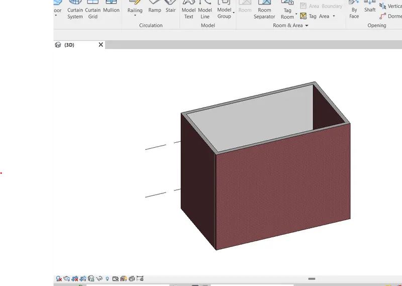
- The 3d view can be navigated by orbit or pan option in the navigation bar. The model unit can be moved on the window or it zoomed or it rotated by using the option in the navigation bar. By clicking on orbit the model is rotated with 360 degrees,By clicking on pan the model can be moved from one position to the other position and by clicking on the zoom option we can zoom in and zoom out of the model.
Result:
- The model is changed to 3d view to get the clear idea about the model in all the directions.The model height can be get to know and the necessaray changes can be apllied to the model if required from the properties browser.
- By using the navigation bar the model unit is rotated or moved or zoom in and zoom out very quickly.
- The Navigated model obtained is shown below.
8.Aim: To create the rectangular lay out of the wall with the size 40'x35' and plot the 3d view of the layout and use the visibility settings for the model unit to convert from the one type of the view to the other type of the view in the revit soft ware.
- The rivet soft ware is used to develop and design the building model.
- Rivet offers a visual of the 3d model of the building and also add muiltiple detail elements to the project to make it realistic as much as possible.
- In the rivet the design concept and the design standards plays much more important and a key role for the design of the building model.
- The lay out of a building defines the boundry of the building or the site. The model is developed and designed with in the limits of the layout.
Procedure:
- Click on the rivet soft ware icon in the PC and open the rivet software and create the new project file with the architectural template.Then a new file with the architectural mode is displayed.
- Now select the Architectural option and it will displays the new menu bar with various options like wall,door,Curtain,roof, column etc.
- Now click on the wall option and the wall can be plotted with the various options like line, rectangular, polygonal etc.
- Now select the line type wall and plot the wall to a size of the 40'x35'.The layout is created as a rectangular shape 40'x35'.
- Now click on the annotate button in the menu bar and select the dimension linear and assign the dimension of the lay out as 40'x35'.
- Now click on the 3d view at the top of the window which will change the 2d view of the layout in to the 3d view of the layout.
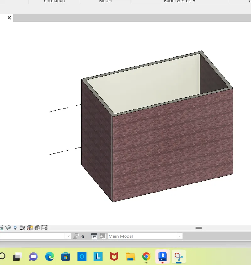
- Now click on the visual style bar on the bottom of the window and select the desired view of the model might be realistic,Hidden or wire frame model.
- The model unit can be turned into selected desired view of the model which will get to know the material properties of the model.
Result:
- The model is changed to 3d view to get the clear idea about the model in all the directions.The model height can be get to know and the necessaray changes can be applied to the model if required from the properties browser.
- By using the view style option the material properties of the model can be identified or the model is formed as a navigation bar the model unit is rotated or moved or zoom in and zoom out very quickly.
- The model with the various view style is obtained is shown below.
9.Aim: To create the rectangular lay out of the wall with the size 40'x35' and plot the 3d view of the layout and apply sunpath to the model using the rivet soft ware.
- The rivet soft ware is used to develop and design the building model.
- Rivet offers a visual of the 3d model of the building and also add muiltiple detail elements to the project to make it realistic as much as possible.
- In the rivet the design concept and the design standards plays much more important and a key role for the design of the building model.
- The lay out of a building defines the boundry of the building or the site. The model is developed and designed with in the limits of the layout.
Procedure:
- Click on the rivet soft ware icon in the PC and open the rivet software and create the new project file with the architectural template.Then a new file with the architectural mode is displayed.
- Now select the Architectural option and it will displays the new menu bar with various options like wall,door,Curtain,roof, column etc.
- Now click on the wall option and the wall can be plotted with the various options like line, rectangular, polygonal etc.
- Now select the line type wall and plot the wall to a size of the 40'x35'.The layout is created as a rectangular shape 40'x35'.
- Now click on the annotate button in the menu bar and select the dimension linear and assign the dimension of the lay out as 40'x35'.
- Now click on the 3d view at the top of the window which will change the 2d view of the layout in to the 3d view of the layout.
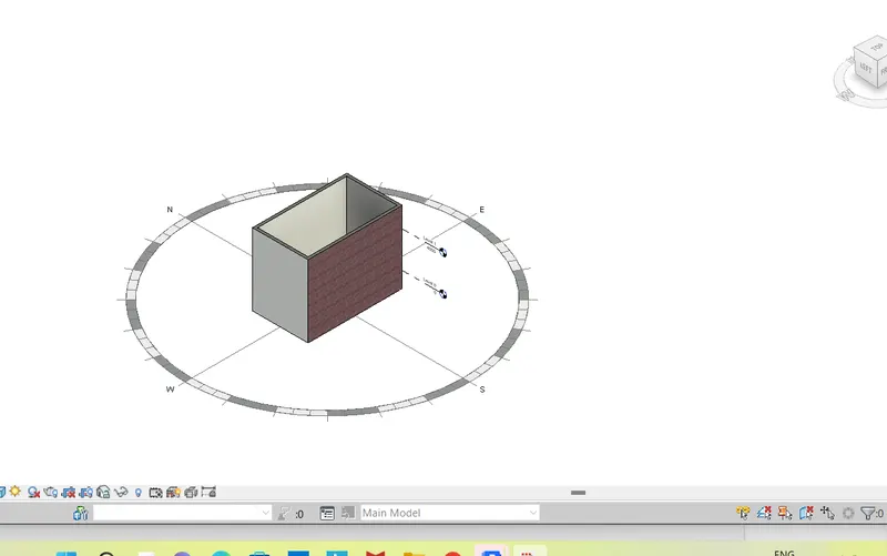
- The sunpath is the option which is used to get to know the sunshade of the model during the sunlight. Rivet consists of a option called sunpath in the bottom of the window ,Click on the sun path on then the position of the sun is created along the model and click on the sunpath off then the path is disappeared alon the model.
- The sun settings is alao modified according to the desired condition.
Result:
- The model is changed to 3d view to get the clear idea about the model in all the directions.The model height can be get to know and the necessaray changes can be applied to the model if required from the properties browser.
- The sunpath on for the specified model is obtained as below.
10.Aim: To create the rectangular lay out of the wall with the size 40'x35' and plot the 3d view of the layout and apply sunpath to the model using the rivet soft ware.
- The rivet soft ware is used to develop and design the building model.
- Rivet offers a visual of the 3d model of the building and also add muiltiple detail elements to the project to make it realistic as much as possible.
- In the rivet the design concept and the design standards plays much more important and a key role for the design of the building model.
- The lay out of a building defines the boundry of the building or the site. The model is developed and designed with in the limits of the layout.
Procedure:
- Click on the rivet soft ware icon in the PC and open the rivet software and create the new project file with the architectural template.Then a new file with the architectural mode is displayed.
- Now select the Architectural option and it will displays the new menu bar with various options like wall,door,Curtain,roof, column etc.
- Now click on the wall option and the wall can be plotted with the various options like line, rectangular, polygonal etc.
- Now select the line type wall and plot the wall to a size of the 40'x35'.The layout is created as a rectangular shape 40'x35'.
- Now click on the annotate button in the menu bar and select the dimension linear and assign the dimension of the lay out as 40'x35'.
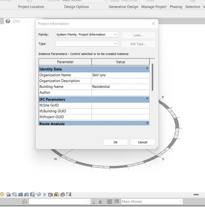
- Click on the manage option in the window and select the project information option and it will display the tool bar in which the project information is included and saved for the future reference.
- The project information option contains the project name,description of the project ,organisation name, issue date,client etc and select ok the project informtion is save.
Result:
- The project information of the bar can be used to identify the out look profile details of the model very quickly and the project information option is in the form shown below.
11. Analyze :
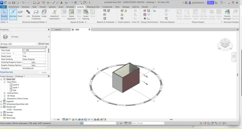
- Analayze option in the rivet software is used to analyze the structure when the load is applied on the model.
- The analyze option consists of boundary conditions and the loading conditions to be applied for the model.The analyze option contains various categories of families like schedules,energy optimisation,Electrical analysis etc.
- The analyzing of the model states the load application and it is helpful to redesign the structure with in the safety limits etc.
- The boundry condition states the extreme end conditions of the model and the load parameters enables the change of the model and load combinations states the total amount of load acting on a particular section of the model.
- The Analyze option is more efficient in the model formtion in rivet software.
- The analyze window of therevit software is shown below.
12. Rivet links:
- The tool insert states the link of rivet file and other options to link the file from cad, The rivet file is linked to work on a two different modules like structural and electrical for the same model.
- The rivet links helps to work on a two relative individual models of a campus which wil help to coordinate between te two models.
- The rivet file is copied and renamed it and it is linked to the
- The auto cad file is linked to rivet,when the cad file is in 2d mode then the file is linked to rivet to change the model in to 3d and as well as the design and analysis of the model. The file is linked in such a way that the changes applied in the auto cad file is automatically reflected in the rivet file also.
- There is another option called manage link which will help to work on a two different models i.e when the two models like structural and electrical model files are linked then we can load or unload the link to view the models.When the electrical file is linked to the structural model then loading the electrical link will execute the electrical model and unloading will degrede the electrical model.
13.Colabrate tab:
- Collabrate tab in the rivet states the work sharing of a particular project.It helps to divide the work of a model.
- Using the collabrate tab the model is worked out by the multiple engineers like structural,Architectural,MEP from the various places.It helps to work on a model from the various geographical places.
- While working in collabrate tab the cetral file is created for the access of the model by the other designers from the various places.Every one should create each individual central model for the easy access of the mode.