Introduction to REVIT concepts
1)
Aim - To create a New Project and Name the Project
Introduction - 1) Revit is an Building Information Modeling software and is product of an Autodesk.
2) It can be useful for Architects , Civil engineer , Structural Engineer , Mechanical Engineer , Electrical and Plumbing
Engineers .
3) It has Benefits over 2D CAD tools . Such as Real time modeling .
4) There are various templates such as Architectural , Structural , Construction and MEP template and We can work
simultaneously by using Collaborate tool .
Procedure -
Step 1)
i) Open the Revit software from deskstop / you can search it from windows tool .
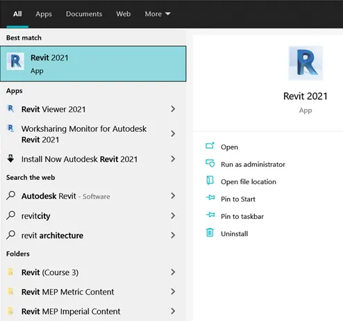
Step 2)
i) Once you open the Revit Software , a following tab will open
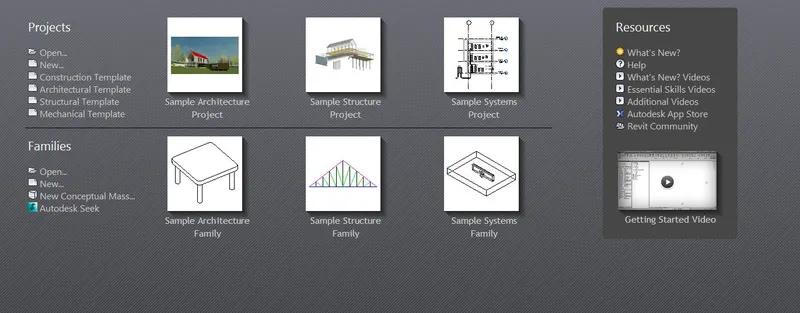
Step 3)
i) Click on New tab , and create a Structural Template
ii) Click on Create New - Project
iii) Click on Okay .
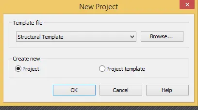
Step 4)
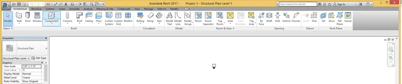
i) Once you click okay , a Working space model will open where we can start designing
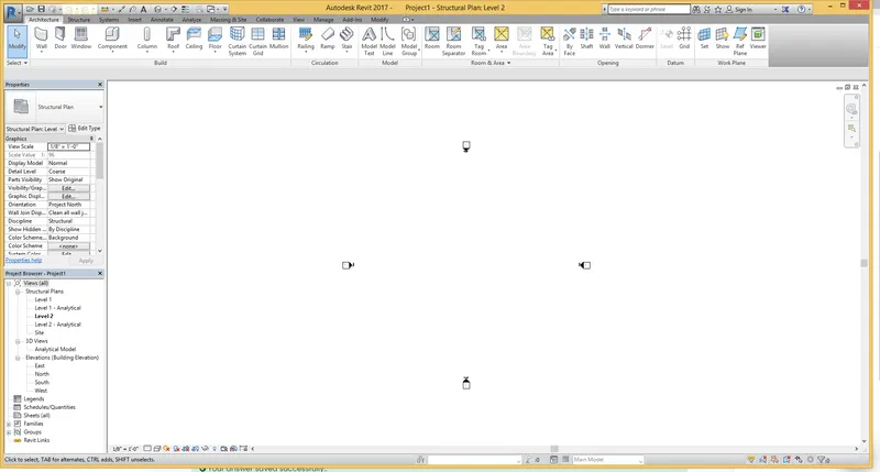
Step 5)
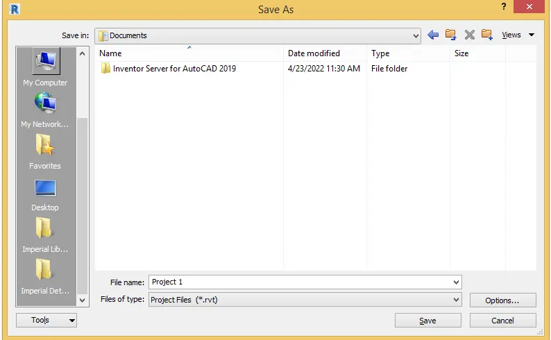
i) There is an option on top left side of screen called as Save .
ii) Click on Save option , a dialogue box will open
iii) File Name - Project 1 and Click on save .
Step 6)
i) Similarly we can create other templates too . by following same procedure .
Results - A New Project is created with the appropriate name
2)
Aim - To save the New project file , close and open using icons from file toolbar
Introduction - 1) Revit is an Building Information Modeling software and is product of an Autodesk.
2) It can be useful for Architects , Civil engineer , Structural Engineer , Mechanical Engineer , Electrical and Plumbing
Engineers .
3) It has Benefits over 2D CAD tools . Such as Real time modeling .
4) There are various templates such as Architectural , Structural , Construction and MEP template and We can work
simultaneously by using Collaborate tool .
Procedure -
Step 1)
i) Open the Revit software from deskstop / you can search it from windows tool .
Step 2)
i) Once you open the Revit Software , a following tab will open
Step 3)
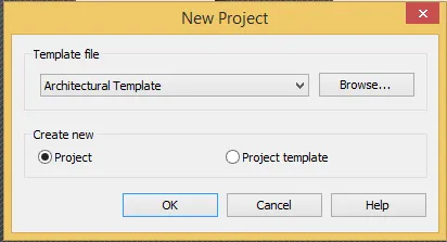
i) Click on New tab , and create a Architectural Template
ii) Click on Create New - Project
iii) Click on Okay .
Step 4)
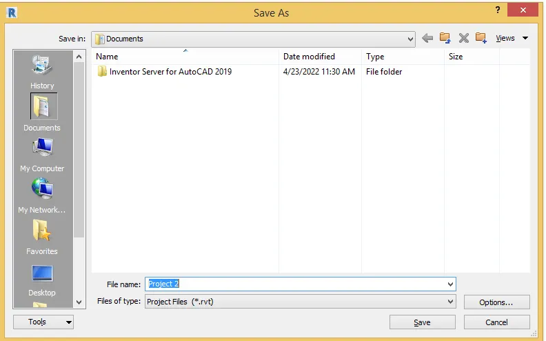
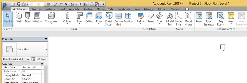
i) Click on Save button
ii) Name the File as Project 2
iii) And Save it .
Step 5)
i) Close the file .
ii) Again open the Revit Software
iii) You will see your Project file 2 on once you open your software .
iv) Click on your file .
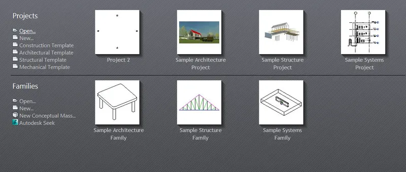
Results - A New project file is created and save it successfully and later on open it from Icon toolbar .
3)
Aim - i) To create Architectural / Structural toolbar familiarize with options to draw a wall .
ii) To create Rectangular layout of wall of size ( 40'-0" x 35'-0") .
Introduction - 1) Revit is an Building Information Modeling software and is product of an Autodesk.
2) It can be useful for Architects , Civil engineer , Structural Engineer , Mechanical Engineer , Electrical and Plumbing
Engineers .
3) It has Benefits over 2D CAD tools . Such as Real time modeling .
4) There are various templates such as Architectural , Structural , Construction and MEP template and We can work
simultaneously by using Collaborate tool .
Procedure -
Step 1)
i) Open the Revit software from deskstop / you can search it from windows tool .
Step 2)
i) Once you open the Revit Software , a following tab will open
Step 3)
i) Click on New tab , and create a Architectural Template
ii) Click on Create New - Project
iii) Click on Okay .
Step 4)
i) Click on Save option on left corner , a dialogue box will open
ii) File Name - Project 1 and Click on save .
Step 5)
i) A by default unit is in Imperical system so we do not need to change the units .
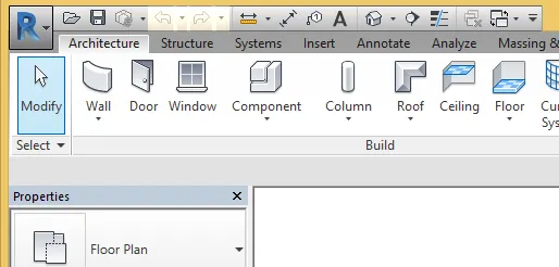
ii) In Home tab- Click on Architectural
iii) There is an option as Wall - Wall Architectural
iv) Click on that .
Step 6)
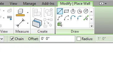
i) Once you click on that , A modify or place wall option will be there
ii) From that click on lines
Step 7)
i) Once you select a line
ii) Keep the cursor on Model space
iii) Draw the horizontal line ( wall) of 40'-0"
iv) And from end point of horizontal line , draw a verical line ( wall) of 35'-0")
v) Similarly Complete a rectangular wall .
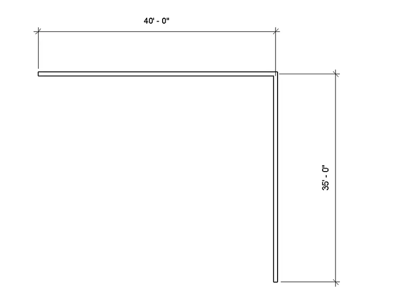
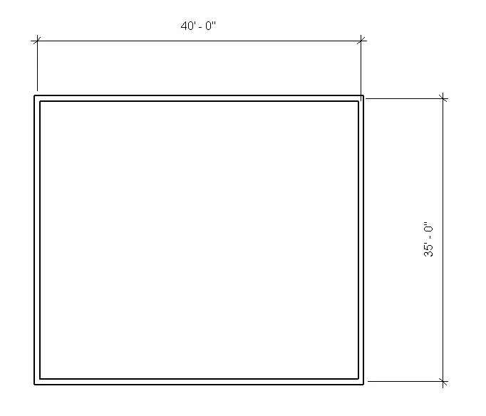
Results - An Architectural template is created and Rectangular wall is drawn of size (40' x 35') using Wall toolbar .
4)
Aim - To give the dimensions by using Annotate toolbar
Introduction - 1) Revit is an Building Information Modeling software and is product of an Autodesk.
2) It can be useful for Architects , Civil engineer , Structural Engineer , Mechanical Engineer , Electrical and Plumbing
Engineers .
3) It has Benefits over 2D CAD tools . Such as Real time modeling .
4) There are various templates such as Architectural , Structural , Construction and MEP template and We can work
simultaneously by using Collaborate tool .
5) Annotation is an important propery . It is used to is identify the element by giving text or giving dimensions
6)It shows the geometrical properties of an element such as Length , Width , Height etc .
Procedure -
Step 1)
i) Open the previous Project from Icon toolbar
ii) Once the project file is open click on Annotate option from home tab / panel
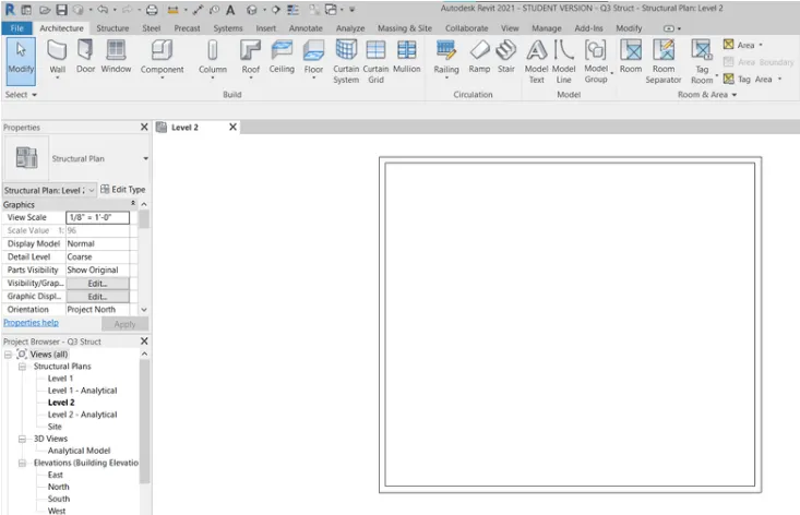
Step 2)
i) After clicking the Annotate toolbar
ii) Click on Aligned dimension option
iii) Place the cursor on the mid point and measure the dimensions of the wall
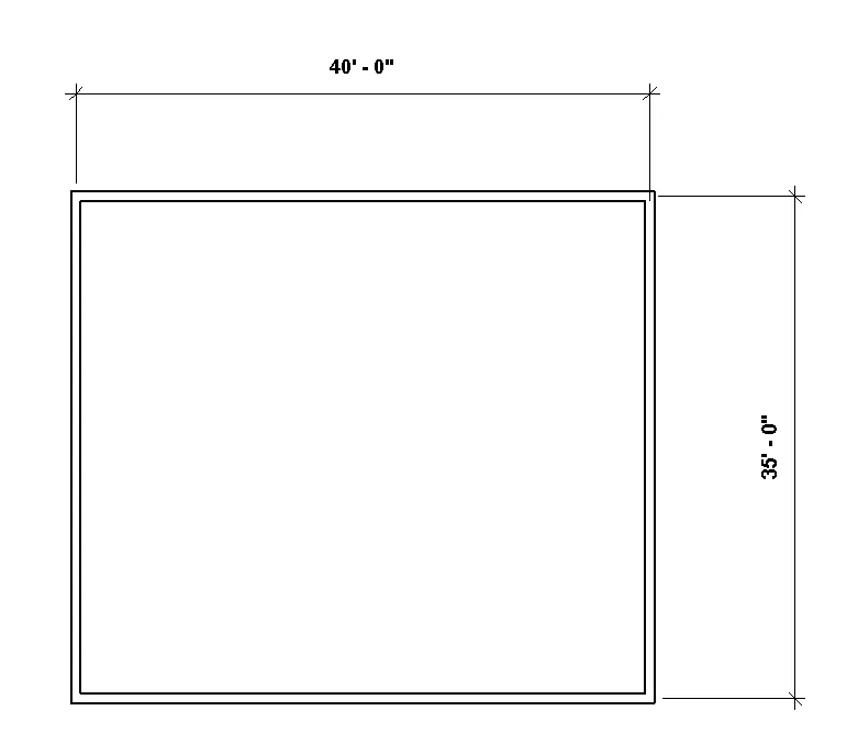
Results - A dimensions is measured by using Aligned toolbar .
5)
Aim - To change the wall type by using Property Browser
Introduction - 1) Revit is an Building Information Modeling software and is product of an Autodesk.
2) It can be useful for Architects , Civil engineer , Structural Engineer , Mechanical Engineer , Electrical and Plumbing
Engineers .
3) It has Benefits over 2D CAD tools . Such as Real time modeling .
4) There are various templates such as Architectural , Structural , Construction and MEP template and We can work
simultaneously by using Collaborate tool .
5) There are different types of wall property are present in Revit and selection wall type is depends on requirement
6) Walls types are - Basic wall , Curtain wall , Stacked wall .
Procedure -
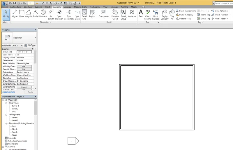
i) Open the File of Question 3 in which we have created walls
Step 2)
i) On bottom left side there is an property box called as Property Browser
ii) Click on that
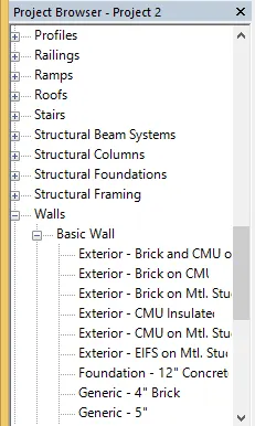
iii) Move down and Click on Families
iv) Again move down and and there is an Wall element
Step 3)
i) Click on Basic wall
ii) and Select whichever material you want
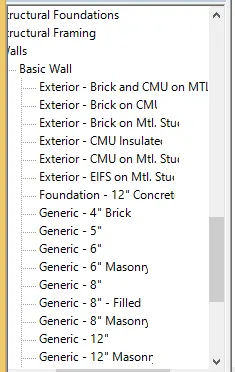
iii) For eg - We select Generic 8"
Step 4)
i) Click on any wall element
ii) A properties box will open on left side
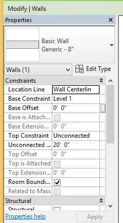
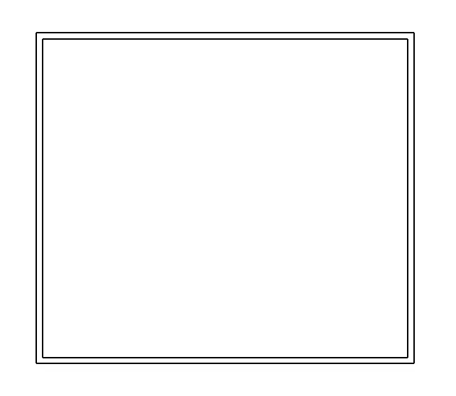
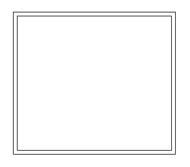
Results - A different wall types has been considered by using properties browser . The Following are the wall properties and the result is shown
for Generic 8" and Generic 12" wall
i) Generic 8" wall
ii) Generic 12"
6)
Aim - To create a 3D view and save the view with appropriate name .
Introduction - 1) Revit is an Building Information Modeling software and is product of an Autodesk.
2) It can be useful for Architects , Civil engineer , Structural Engineer , Mechanical Engineer , Electrical and Plumbing
Engineers .
3) It has Benefits over 2D CAD tools . Such as Real time modeling .
4) There are various templates such as Architectural , Structural , Construction and MEP template and We can work
simultaneously by using Collaborate tool .
Procedure -
Step 1)
i) Open the File of Question 3 in which we have created walls
Step 2)
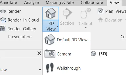
i) Click on View toolbar from home panel
ii) Click on 3D View
Step 3)
i) Once you click on 3D View
ii) A 3D view will open in Modal space
iii) From project browser , click on 3D view
iv) Right Click on it and Rename it as SW Isometric View
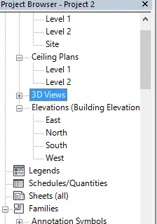
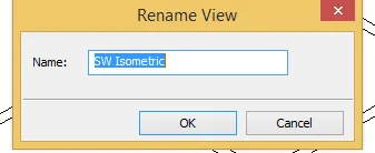
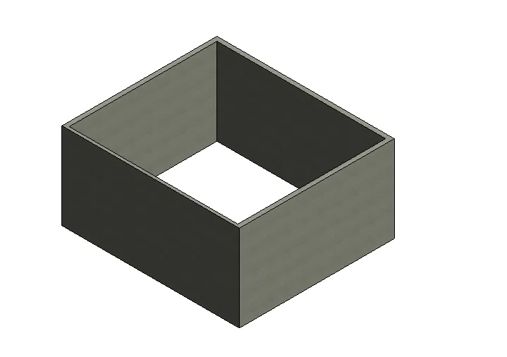
Results - A 3D View is created with name as SW ISOMETRIC View
7)
Aim - To navigate through the 3D model using the view cube. Orbit/pan through the model layout created
Introduction - 1) Revit is an Building Information Modeling software and is product of an Autodesk.
2) It can be useful for Architects , Civil engineer , Structural Engineer , Mechanical Engineer , Electrical and Plumbing
Engineers .
3) It has Benefits over 2D CAD tools . Such as Real time modeling .
4) There are various templates such as Architectural , Structural , Construction and MEP template and We can work
simultaneously by using Collaborate tool .
Procedure -
Step 1)
i) Open the File of Question 3 in which we have created walls
Step 2)
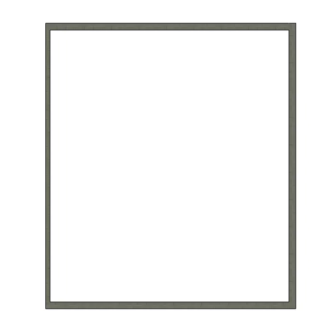
i) Click on View Cube which is there on Right side of Model Space .
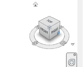
ii) Click on Front , Top view to see the different views
Step 3)
i) Below the View cube , there is an option of Navigation Wheel
ii) Click on that
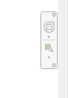
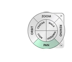
iii) Click on Navigation Wheel
Step 4)
i) Click on Orbit to start the 3D view
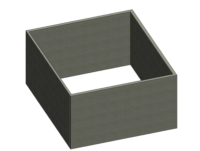
Step 5)
i) Now Click on Pan to move through modal space
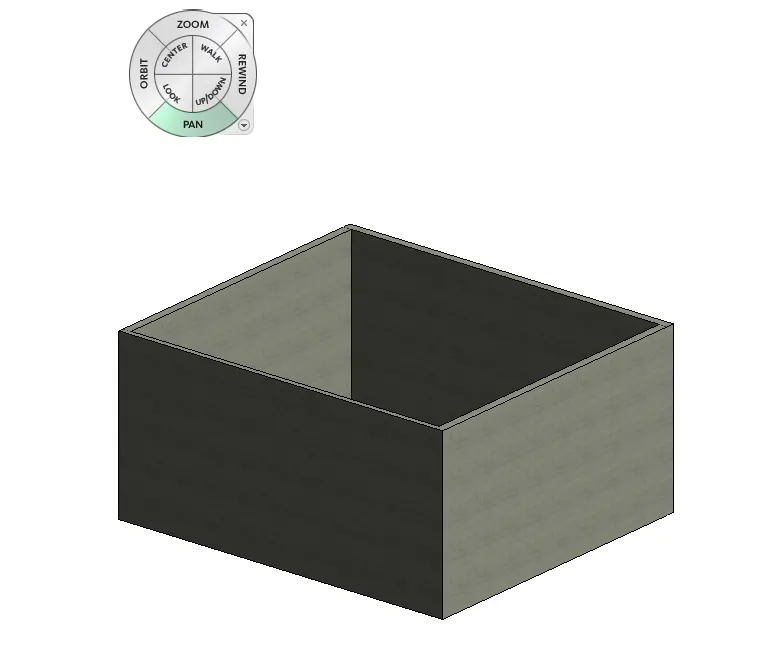
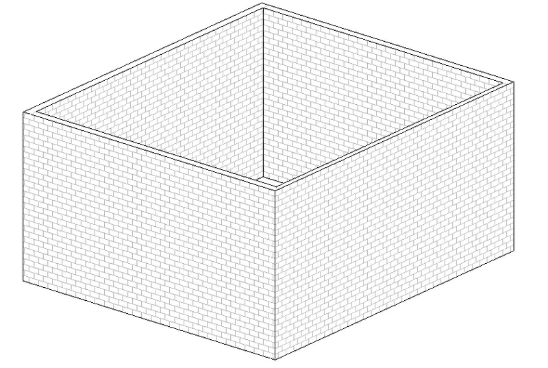
Results - A Navigate through the 3D model using the view cube is shown and Orbit/pan through the model layout created
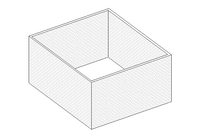
8)
Aim - To use the visibility settings option to switch model to shaded, realistic, hidden lines options .
Introduction - 1) Revit is an Building Information Modeling software and is product of an Autodesk.
2) It can be useful for Architects , Civil engineer , Structural Engineer , Mechanical Engineer , Electrical and Plumbing
Engineers .
3) It has Benefits over 2D CAD tools . Such as Real time modeling .
4) There are various templates such as Architectural , Structural , Construction and MEP template and We can work
simultaneously by using Collaborate tool .
Procedure -
Step 1)
i) Open the File of Question 3 in which we have created walls
Step 2)
i) At bottom there is an option called as Visual Style ( Cube type icon )
ii) Click on that
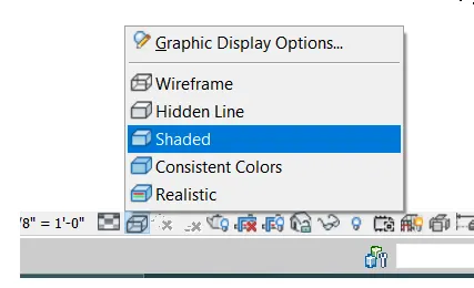
iii) and Select the views options such as Hidden lines , Shaded and Realistic
Step 3)
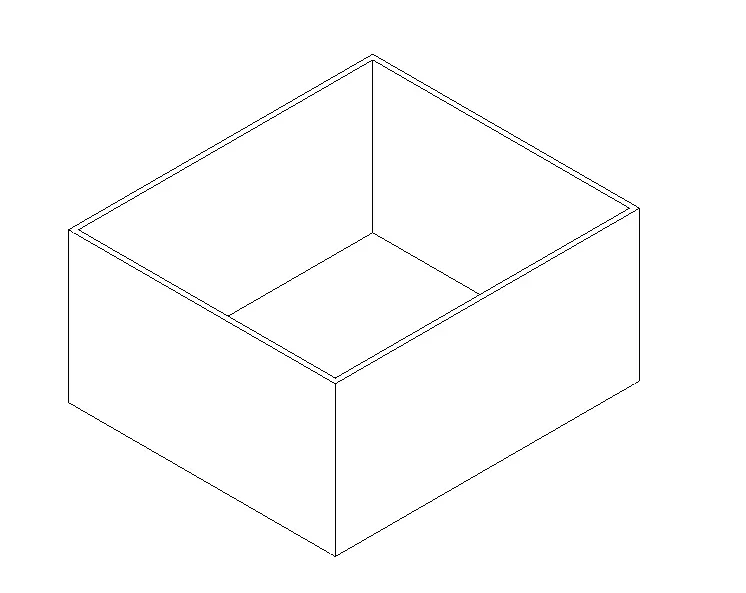
i) Hidden Lines
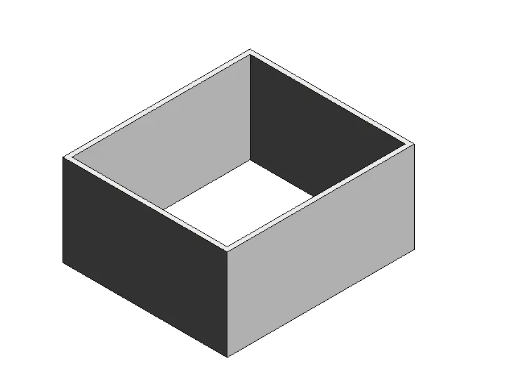
ii) Shaded
iii) Realistic
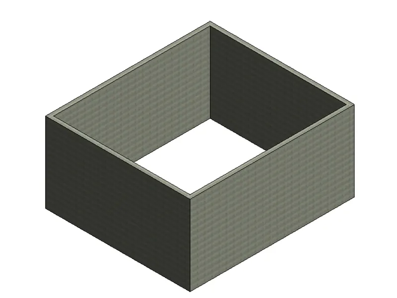
Results - A Model has been switched to Hiddden lines , Shaded and Realistic view by using visibility settiings .
1) Hidden lines
2) Shaded
3) Realistic
9)
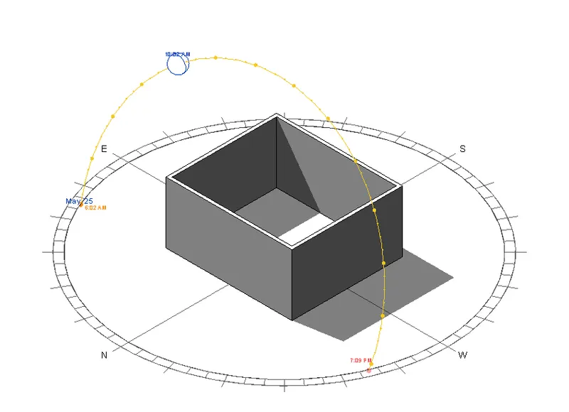
Aim - To turn the sun path on and off to view shadings in the layout created
Introduction - 1) Revit is an Building Information Modeling software and is product of an Autodesk.
2) It can be useful for Architects , Civil engineer , Structural Engineer , Mechanical Engineer , Electrical and Plumbing
Engineers .
3) It has Benefits over 2D CAD tools . Such as Real time modeling .
4) There are various templates such as Architectural , Structural , Construction and MEP template and We can work
simultaneously by using Collaborate tool .
Procedure -
Step 1)
i) Open the File of Question 3 in which we have created walls
Step 2)
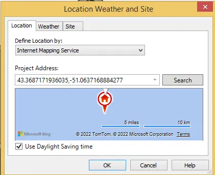
i) Set the locatios
ii) For that click on manage - locations
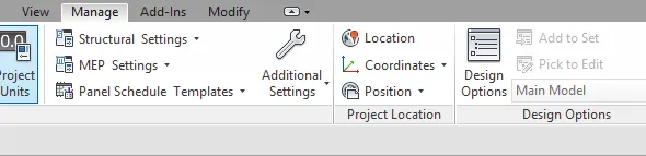
iii) Set the locations
Step 3)
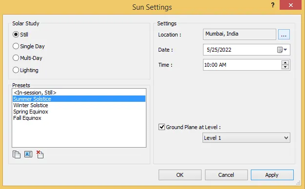
i) Click on Sun Setting
ii) Location - Mumbai India
iii) Solar study - Still
iv) Preset - Solstice
v) Click on Okay
Step 4)
i) At bottom there is an option as Sun path
ii) Click on that
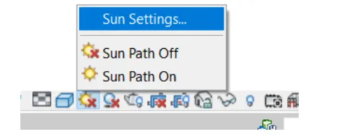
iii) Turn on tha Sun path On
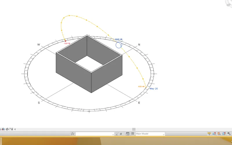
Step 5) For Shadow
i) To turn on the Shadow , theer is an option at bottom
ii) Click on Shadow on
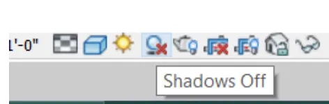
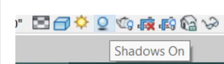
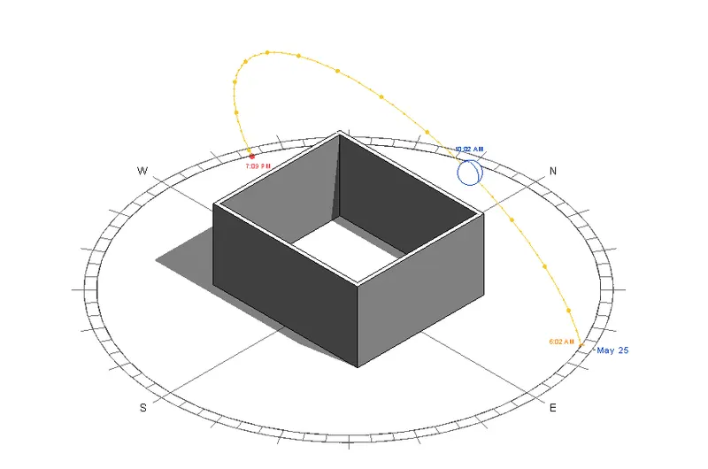
Results - A Sun Path is on and Shadow is also created by using sun path and shadow option .
Followings are the views
i) SW Isometric
ii) SW ISOMETRIC
10)
Aim - To use the Manage toolbar to enter project settings, project name, and project issue date
Introduction - 1) Revit is an Building Information Modeling software and is product of an Autodesk.
2) It can be useful for Architects , Civil engineer , Structural Engineer , Mechanical Engineer , Electrical and Plumbing
Engineers .
3) It has Benefits over 2D CAD tools . Such as Real time modeling .
4) There are various templates such as Architectural , Structural , Construction and MEP template and We can work
simultaneously by using Collaborate tool .
Procedure -
Step 1)
i) Open the File of Question 3 in which we have created walls
Step 2)
i) Click On Manage option from home panel
ii) Click on Manage

Step 3)
i) Click on Project Informations
ii) Enter the data
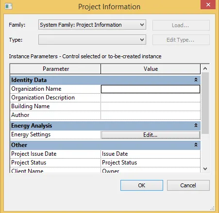
iii) Add the details,
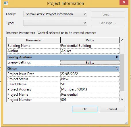
Results - The Project Information is added using Manage Toolbar .
Following are the details
11) Analyze toolbar - i) Ananlyze toolbar is used for detailed analysis of Structural Plan which is an product of Autodesk
ii) A Structural model is created . Once model is created all the properties are assigned to the model and
it can be analyzed by using Analyze toolbaar .

Analyze toolbar has following component -
1) Analytical model - i) It contains Boudary conditions , which defines point ,line , area boundary boubndary conditions in analuytical model
ii) It contains Load such as Point load , area load and line load to the model
iii) It contains Load cases and Load comnbinations which can be considered as per Design code .
2) Analytical Model Tool - i) Adjust Analyrical Model of the structural member in relation to those of the elements to which it joins
ii) Reset Analytical model -It is an alignment method to Auto - detect
ii) Check Member Supports - It verifies the structural member such as beam column slab and wall are joined to
suporting elemnets .
iv) Consistency Check - It verifies the physical and analytical model for consistency.
3) Spaces and Jones - i) This toolbar is used to create space separators .
ii) Space separators are used to separate different rooms of the plans to differentiate the rooms
iii) It also contains Seperatoe tag to label the project .
4) Reports and Schedules - This tab create a detailed report of the following elements
i) Heating and Coolings loads
ii) Panel Schedule
iii) Schedule / Quantity
iv) Duct presssure loss report
v) Pipe presssure loss report
5) Check System - i) It check duct system , pipe system and verifies properly connected and valid system assignments .
ii) It also shows the disconnect circuit .
6) Colour - i) This is used to show the duct or pipes element .
7) Energy Analysis - i) Enenrgy analysis toolbar is used to increases the building energy performance .
ii) 1st Step is to create a Energy Model
iii) 2nd Step is to Run Energy Simulations
iii) 3rd Step is to Display the graphical results simulations and compare it .
iv) This tools provides clear guidance and direction towards better building Energy performance
12) Links - i) In Revit we can link other model to current model .
ii) The linking of model helps to create better and efficient model in Revit .
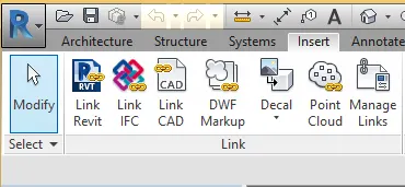
1) Link Revit - i) We can link another model to the current model .
ii) It specify the relative location of individula buildings on campus or coordinates efforts across the disciplines
2) Link IFC - i) Link an IFC file to the current project to reference its informations for additional design work .
ii) If you later make any changes to the original IFC files and reload the link the project updates to the reflect the IFC changes
iii) Before linking IFC files use Open - IFC options to specify the project template to use and to load a file that maps IFC classes
to Revit Categories .
3) Link CAD - i) Link Cad file to the current Revit project
ii) Linking similar to having an xref in autocad .
iii) When the original linked file changes these changes are reflected in the file when you reload the project .
4) DWF Markup - i) Links marked up DWF files into a Revit project so you can see the markups on corresponding sheets
ii) The DWF markups are placed as an important symbol on sheet in Revit project
iii) The markups are pinned in place so you cannot move or manipulate them.
5) Point Cloud - i) Link a point cloud file to the current Revit project
ii) The point cloud tool can be used to index a raw format point cloud file for use in project .
iii) When linked into a project point clouds can provide references when you are placing or editing modal elements .
6) Manage Links - i) Provides options for managing links to buildings models , CAD files , DWF files and point clouds
ii) From the manage links dialog , we can also link Revit models and CAD files to the current project .
13) Collaborate - i) Revit provides many ways to collaborate with team members who are working on software .
ii) As we have seen the Links option , it also works as Collaborate option on which simultaneous work can be done
iii) Users on same Local Area Network can work together in the same Revit Model using Revit Work Shaing .
iv) For eg , If an MEP engineers is working on some model but if Structual Enginers also want to work on same model
so they can use Collaborae tool bar to work on same model simultaneously .

v) In Modeling it helps the team members of different discipline such as Architectural , Structural , MEP can work together
vi) The efficiency of the work is high , fast and accurate as we are doing simultaneous work
vii) We do not have to wait for another discipline to complete the model and to start the next work . Along with them we can also start our
work . which save the time as well as increases efficiency of the work .