Introduction to REVIT concepts
1) Aim:
To create a new project in revit
Procedure:
Step 1: double click on revit icon in the desktop
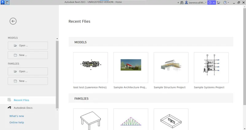
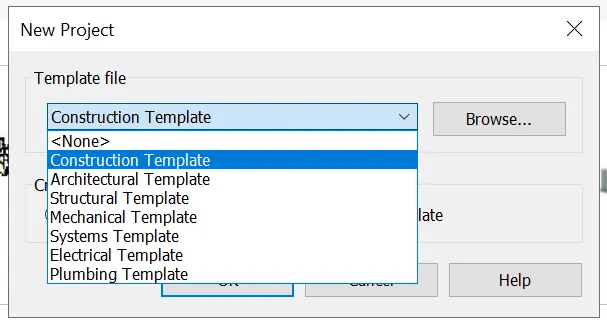
Step 2:click the respective template such as architecture, structure and system on the list
Step 3: towards the left top there will be file menu by clicking on that in the dropdown save will be availabe by clicking that we can able to save it by navigating the particular folder.
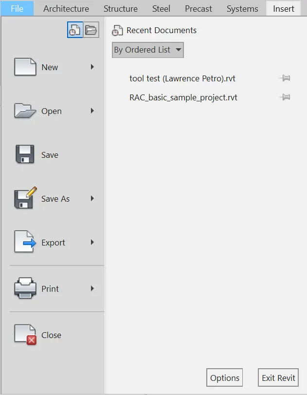
Result: File is created.

2)
Aim: To close and open the created file by using file toolbar.
Procedure:
Step 1: click file menu.
Step 2: click close option to close the current file.
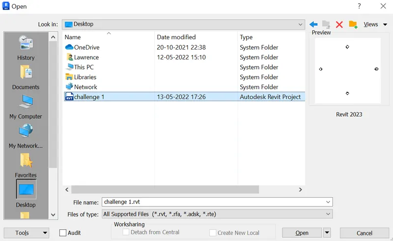
Step 3:click on open and navigate to the file to open.
Result:
3)
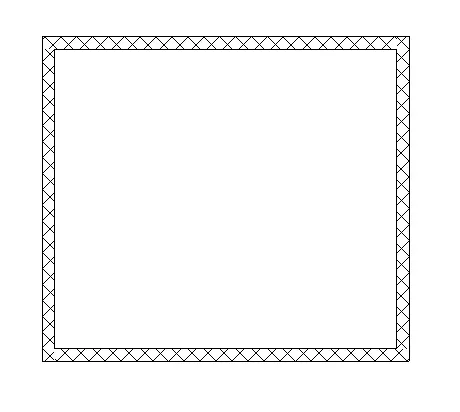
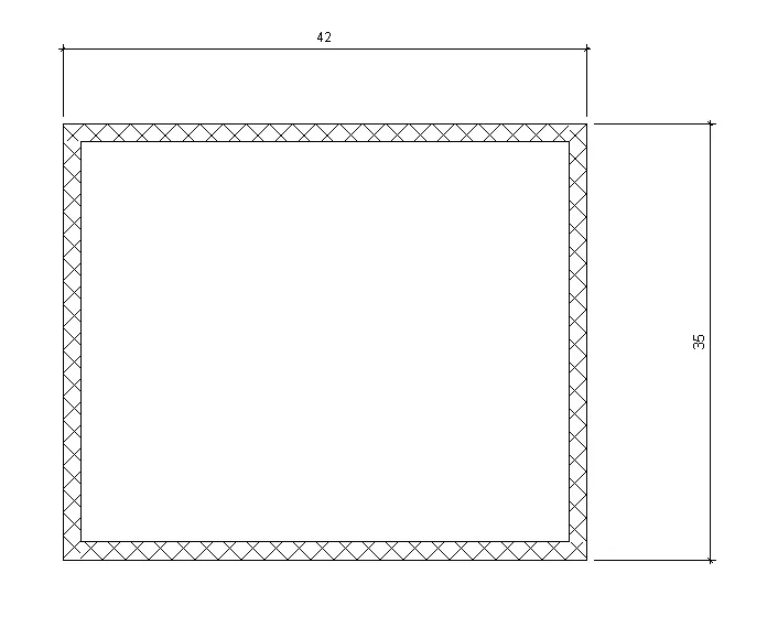
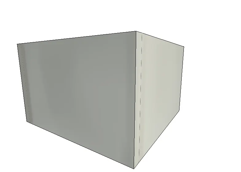
Aim: To create a rectangular layout of walls of about 40’-0” X 35’-0”
Procedure:
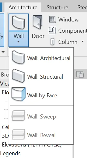
Step 1:In the architecture tab the first option will be wall. By clicking on that we can able to see a dropdown menu filled with options architecture and structure wall. To activate, click on the architecture/structure wall.
Step2:On the ribbon there are plenty of model options like line, rectangle, circle, polygon etc,.
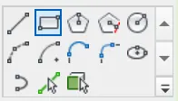
Step 3: Create a wall using rectangle tool and later the dimensions as 40’-0” X 35’-0”
Result:
4)
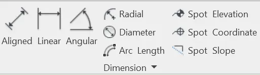
Aim: From the Annotate toolbar use the aligned option to add dimensions to the layout.
Procedure:
Step 1: click the annotate, in the domensions panel use aligned tool to dimension the walls by clicking the edges.
Step 2: by clicking the walls alter the temporary dimensions by double clicking.
Result:
5)
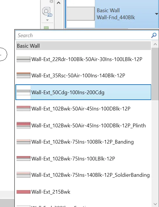
Aim: To switch the wall types by using the property browser.
Procedure:
Step 1: Click the wall that to be changed.
Step 2: select the wall type in the property browser
Resut:
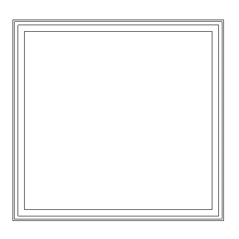
Wall type changed to exterior.
6)
Aim: Create a 3D view from the view toolbar and save the view with the appropriate name.
Procedure:
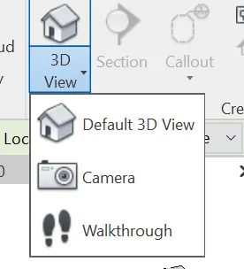
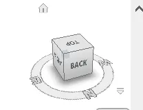
Step 1:click the view tab. In that click the camera option in the 3D view menu. By using click and drag option we can generate various 3D views or by right clicking the view cube and save option can generate various 3D views.
Step 2: The created view will be updated in the project browser.
Result:
7)
Aim: Navigate through the 3D model using the view cube. Orbit/pan through the model layout created.
Procedure:
Step 1: In the quick access tool bar, click the home icon (3D view) which takes us to the 3D view.

Step 2: Here in the right top of the model space we can identify the view cube. By rotating the view cube our model also parallely rotated.
Result:
8)
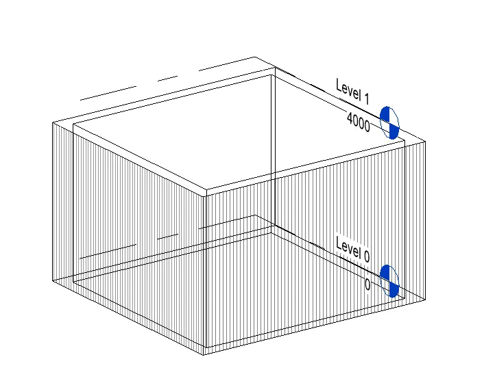
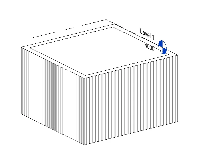
Aim: Use the visibility settings option below to switch model to shaded, realistic, hidden lines options.
Procedure:
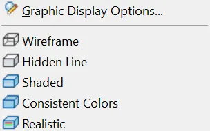
Step 1:In the bottom of the model space just above the status bar there are some list of option related to views. In that the cube icon is said to be the visibility option. The drop down as follows
- Wireframe
- Hidden lines
- Shaded
- consistent color
- Realistic
Step 2:
click on wireframe and hidden line to change the visibility.
result:
9)
Aim: Turn the sun path on and off to view shadings in the layout created.
Procedure:
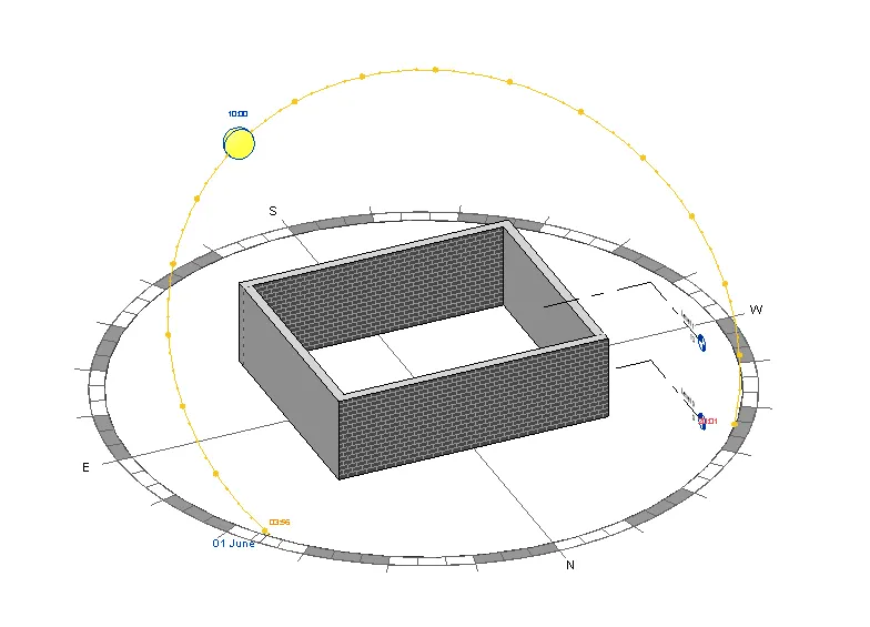
Step 1:Just above the status bar we can find the sun path settings. This option is used to show the sun revolution with respect to our model, say the position of sun at the respective time intervals and shadows as well.

step 2:on clicking the option we have to set the location,date and time as per the sun settings needed.
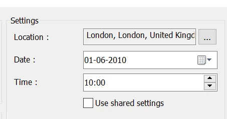
Result: if we set the time as 10 AM, sun travels towards the west and the shadows to the opposite side.
For example:
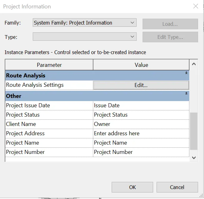
10) To add any information about the project say project name, contractor, completion date, Issue date and other relevent information can be provided in the project information menu which is available in the manage tab under the settings panel.
11) Analyse toolbar is used load calculations for structures and to take shedules for various diciplines like mechanical, electrical etc.
In specific loads like
Point Load
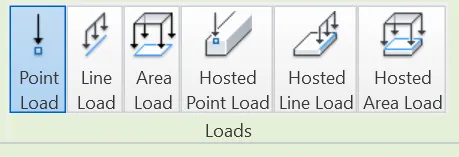
and also panel schedules, heat and cool loading for HVAC, circuit and pipe line checks.
12) By using various options we can import revit files to different diciplines. The options are Link revit, link cad and import cad.
- To link revit architecture to structure, we can use of link revit option to make it done.
- After inmorting the cad if there is an updation needed as per the core file by using link cad we can update the cad file.

13) Collabration in revit is a workflow, in this N number of people can can work in a single file by creating a central file. work sets will be created for each user who is going to work in the central file.In other words work sharing.