3D Creation of Celing, Roof, Architectural plan, Structural plan, Sectional view, Elevation view and Camera specific view for a house plan using REVIT
1) Based on the project saved from Week 3, proceed from the First Floor Level. Model a Ceiling from the architecture tab above the walls at the first-floor level.
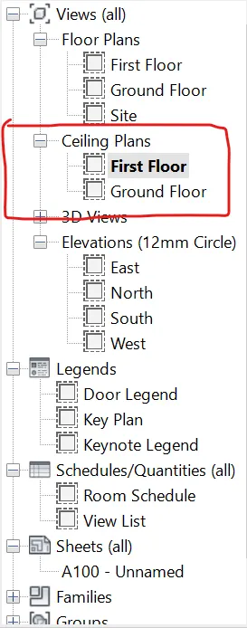
- Activate first floor in ceiling view in the project browser.
- Go to architecture tab>ceiling(build panel).
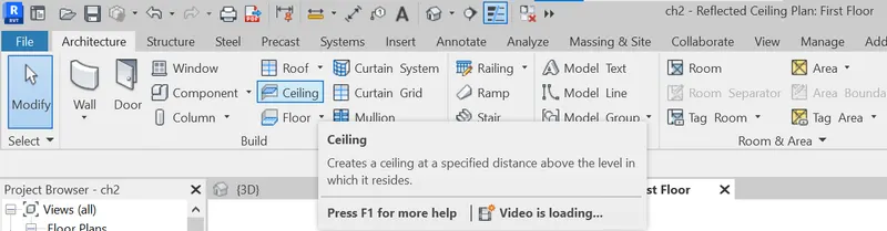
- ceiling can be created by either by automatic or sketch method.
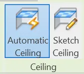
- click sketch method.
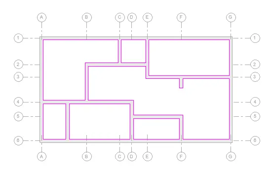
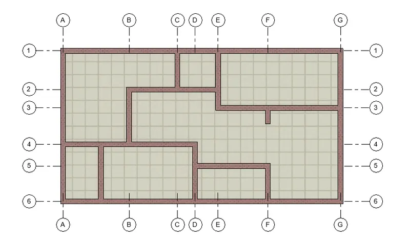
- By using model tools create boundries where ever needed (closed boundries)
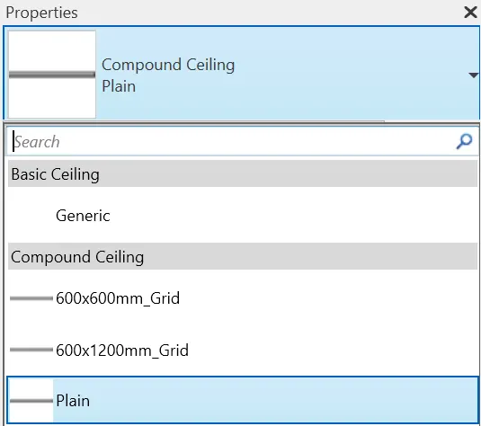
- Select the type of ceiling in the property browser.
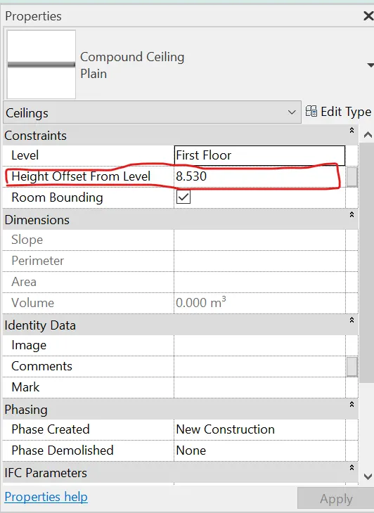
- Alter the height of the ceiling in the project browser in "Height offset from level"
Result:
2) Model a roof above the ceiling by selecting the footprints of the ceiling. Using the adjustment toolbars appearing on-screen adjust the roof slope to 10 degrees
- Activate "first floor" floor plan in the project browser
- Go to architecture tab>Roof - Roof by foot print (built panel)
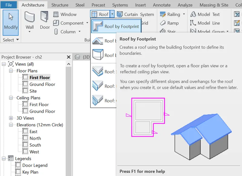
- Create boundry sketch (closed boundry) by using model tools, which is available in the ribbon.
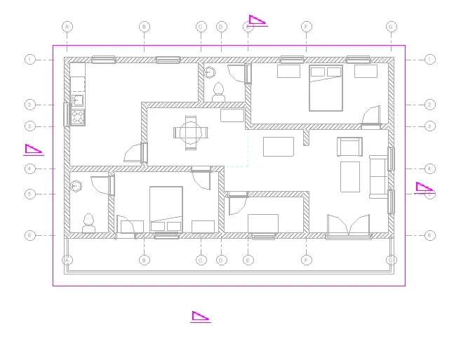
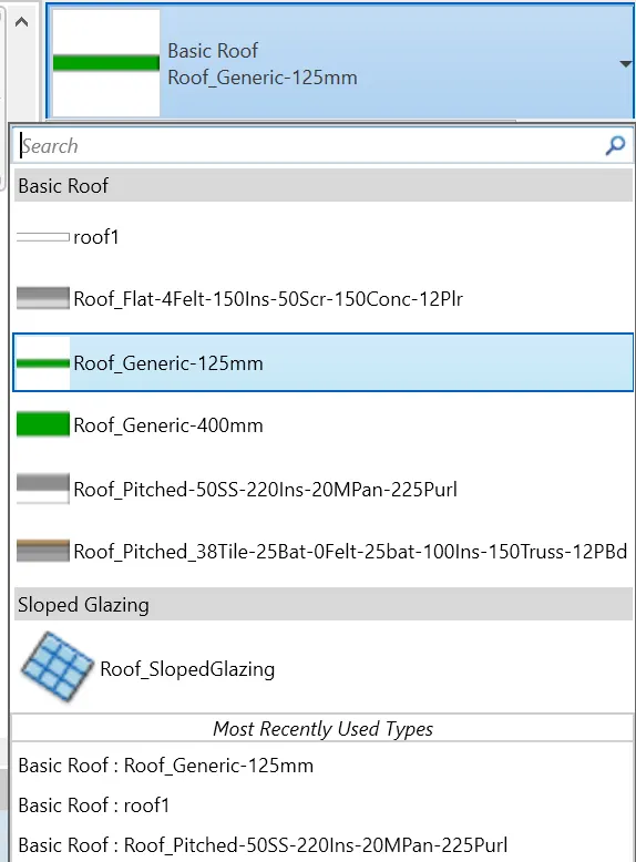
- Select the type of floor in the property browser.
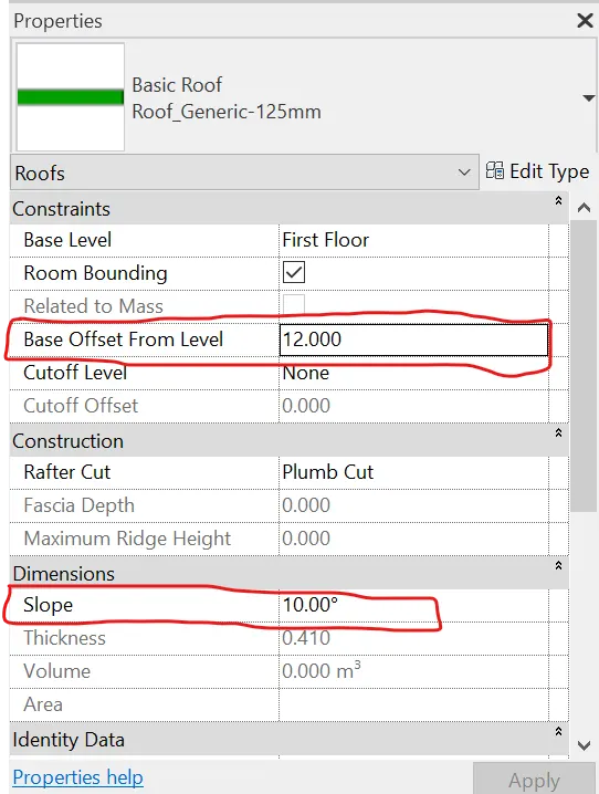
- To alter the height offset of the roof use "base offset from level" in thr property browser.
- To alter the slope (10 degree) value use "slope" option in the property browser.
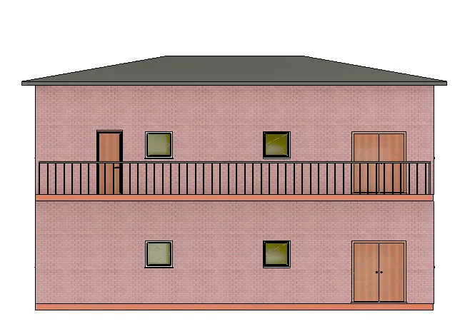
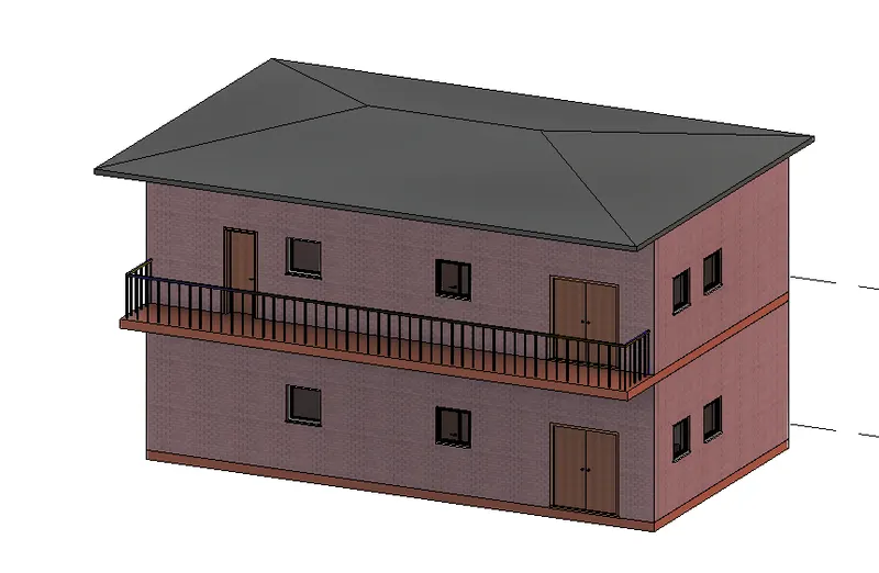
Result:
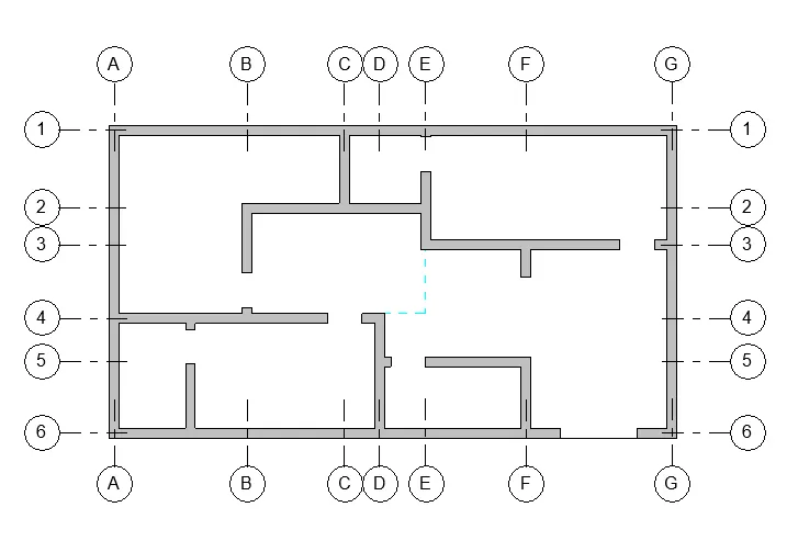
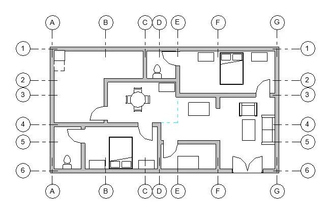
3) Using the file saved from weeks 2 to 4, create plan views for ground floor level and first-floor level including all the walls, floors, and components. Separate them to
architecture and structural plans
- Activate "ground floor" plan view in the project browser.
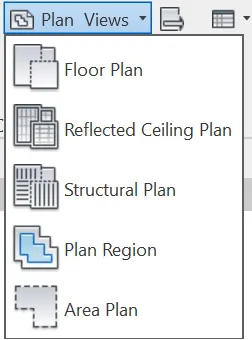
- Go to view tab>plan views>structural plan.
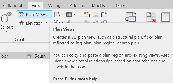
- Click Structural plan in the drop-down.
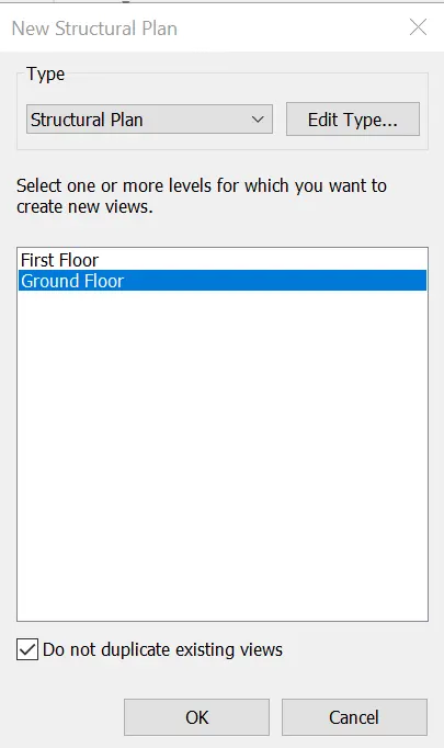
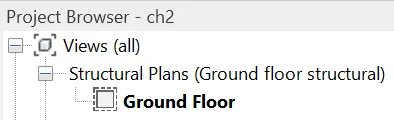
- Select the Ground floor plan to convert to structural plan dicipline and duplicate it to avoid the change in originality.
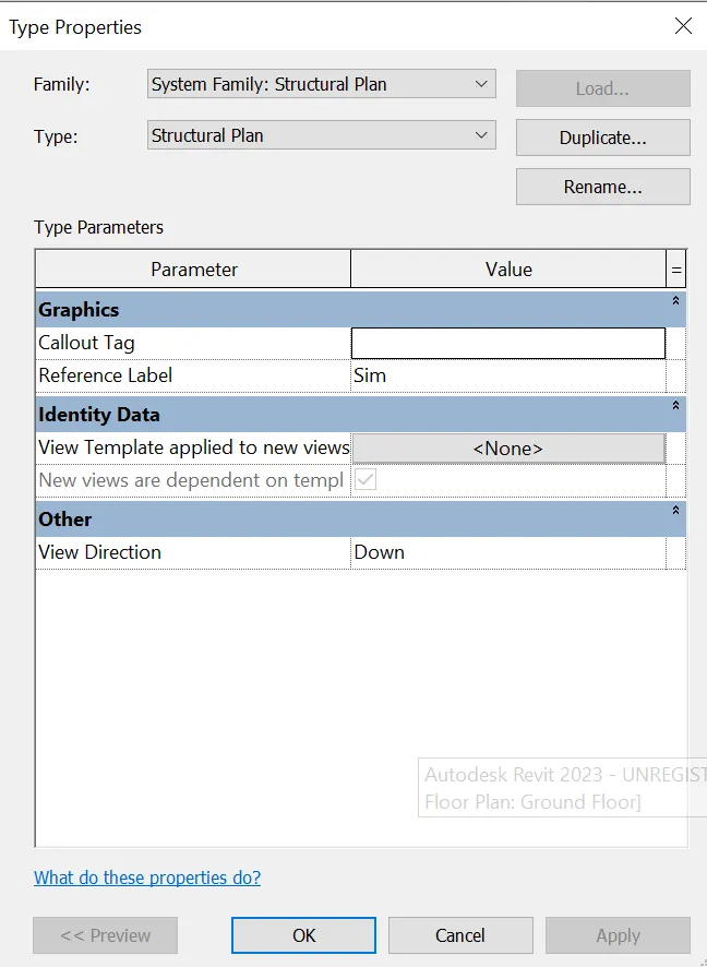
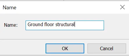
Result:
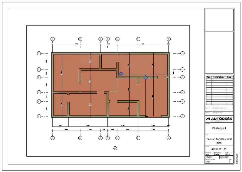
Structural Plan:
Architectural plan:
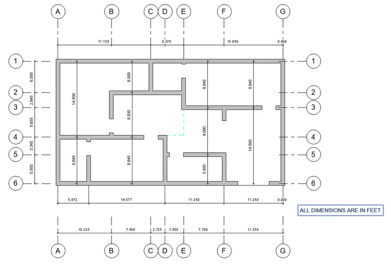
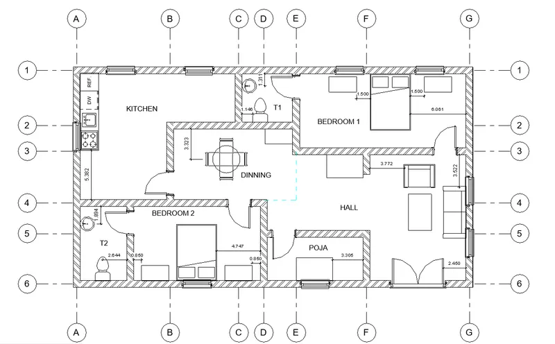
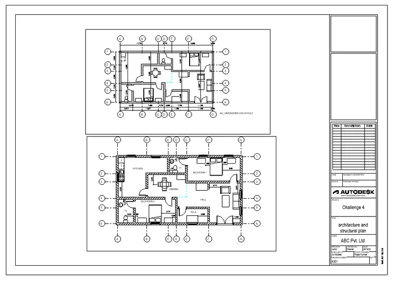
4)Using annotate toolbar add dimensions to all the walls and floors with reference to the longitudinal and transverse grids created in the project file.
- Go to annotate tab>Dimensions>Aligned dimensions.
- Click the component edges to place the dimensions.
5)Create a sheet template from the view tab and adjust the parameters on the sheet to add appropriate views.
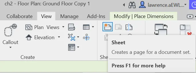
- Go to view tab>Sheet (sheet composition)
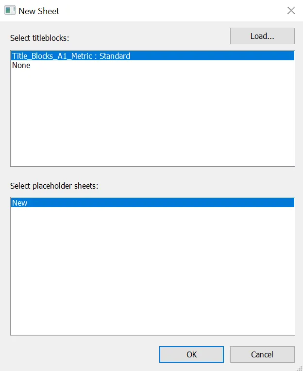
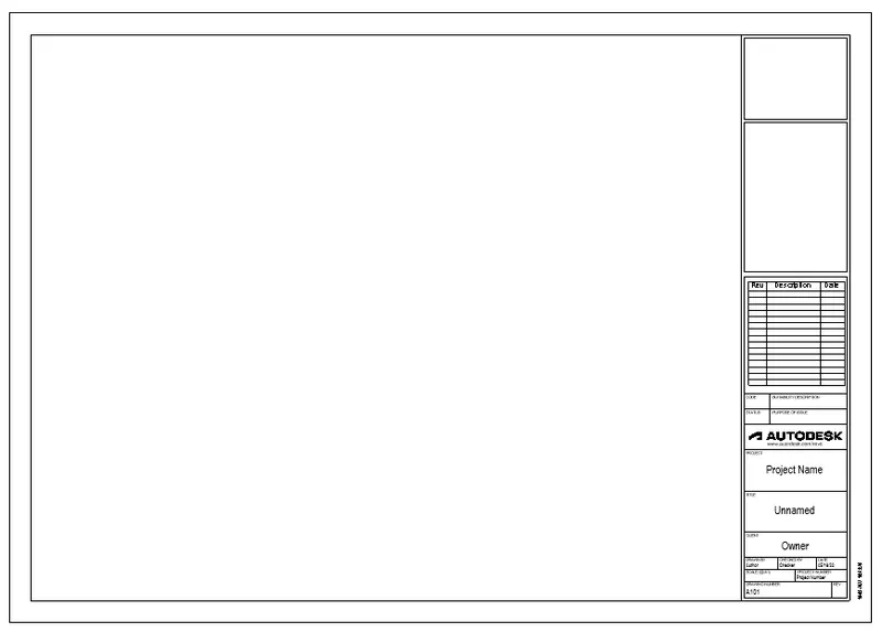
- Select the sheet template to place the views.
To place the view in the sheet
- click place view>select the view in the list to place.
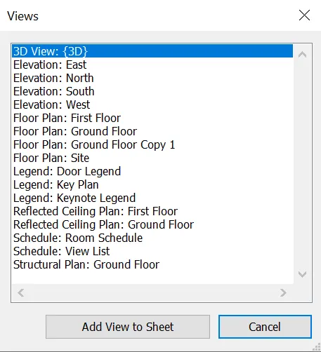
To edit the parameter in the sheet.
- double click the parameter to edit.
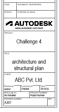
Result: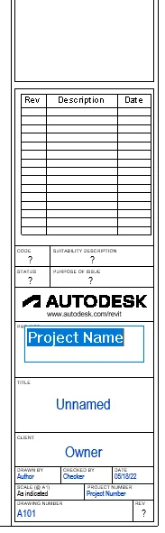
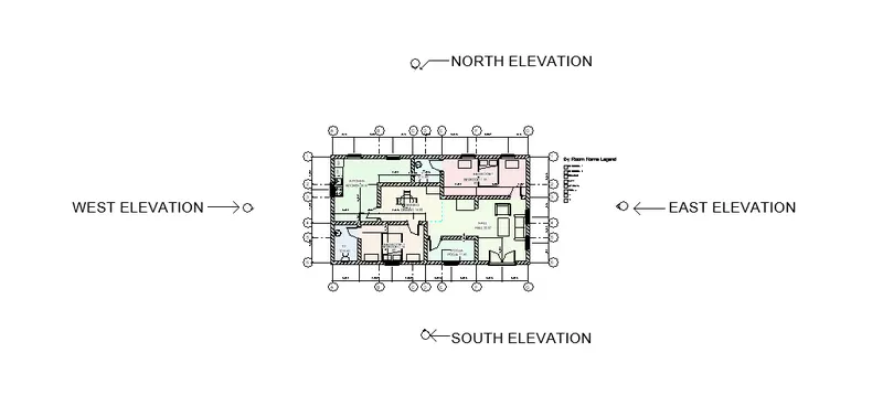
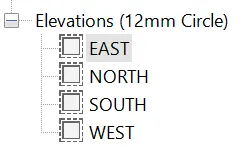
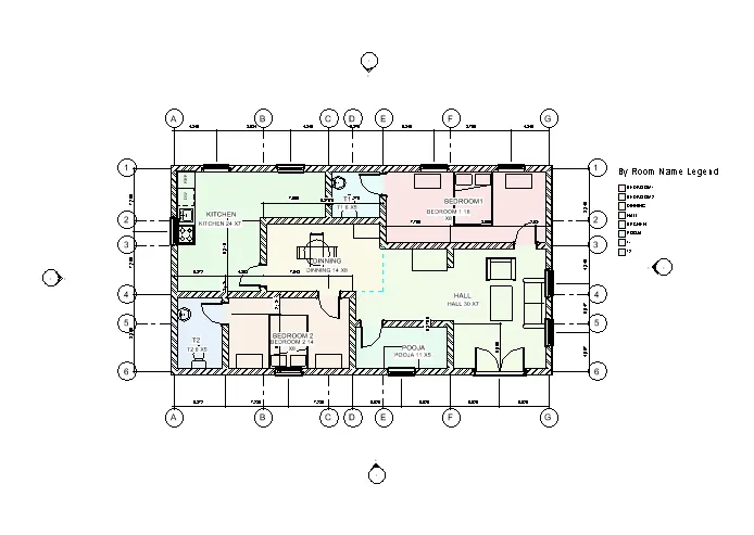
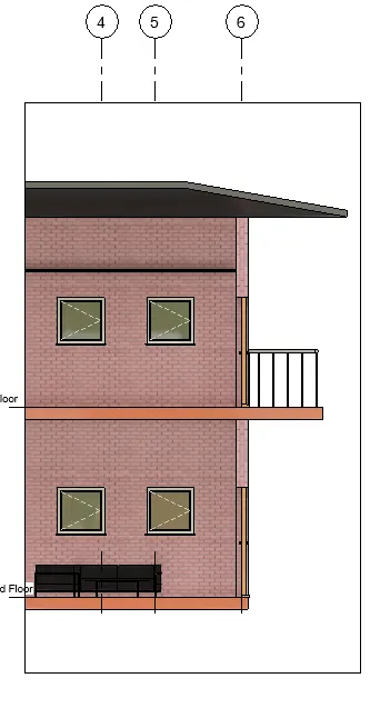
6) Using the elevation tab create the elevation views, looking at your building from East, North, South, and West
- Go to view tab> Elevation (create panel).
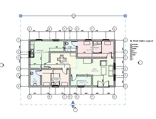
- Click the elevation hold, drag and place where ever the elevation is needed.
- To adjust the range click the tip of the elevation and drag drag the boundary.
Result:
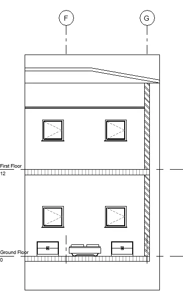
7)Produce section cut through each room either cutting across longitudinally or in a transverse direction.
- Go to view tab>Section(create panel)
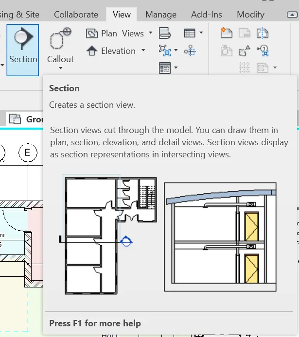
- Click and drag to create a section
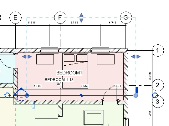
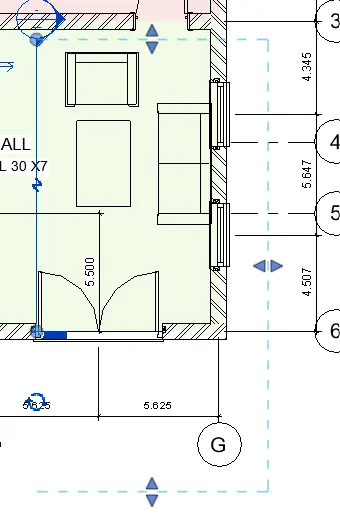
- Right click the section head>Go to view or double the section to open the secttion view.
Result:
8)Classify the views, Plan Views, Section Views, and Elevation views to either Design or Documentation category using Properties browser.
- Go to view tab>Sheet (sheet composition)
- Select the sheet template to place the views
- Click place view>select the view in the list to place
- Double click the parameter to edit
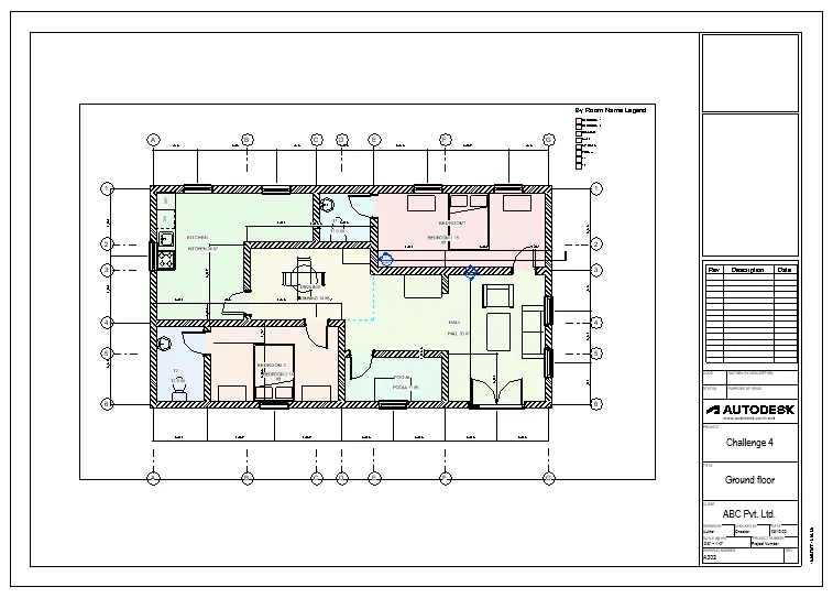
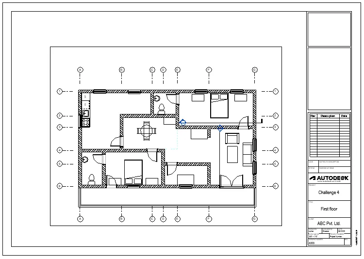
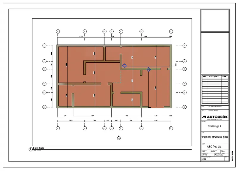

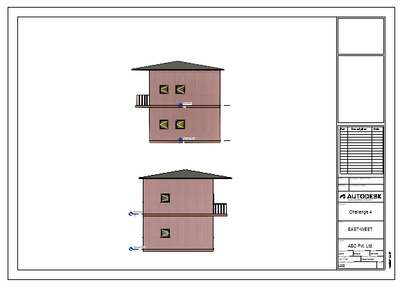
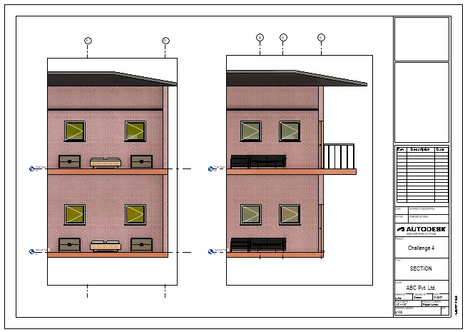
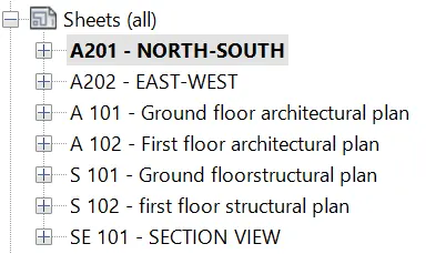
9) Using the sheet template produced create multiple sheets as follows
a. A 101- Ground Floor Architecture Plan.
b. A 102- First Floor Architecture Plan.
c. A 103- Roof Plan.
d. S 101- Ground Floor Structural Plan.
e. S 102- First Floor Structural Plan.
f. S 103- Roof Framing Plan.
g. A-201- North-South Elevations.
h. A-202- East-West Elevations.
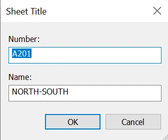
- To rename the sheet name, right click the sheet in the project browser> Rename
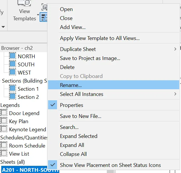
- Enter the sheet number and name in the "sheet title" dialogue box.
Result:
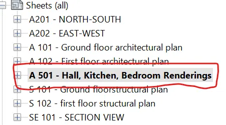
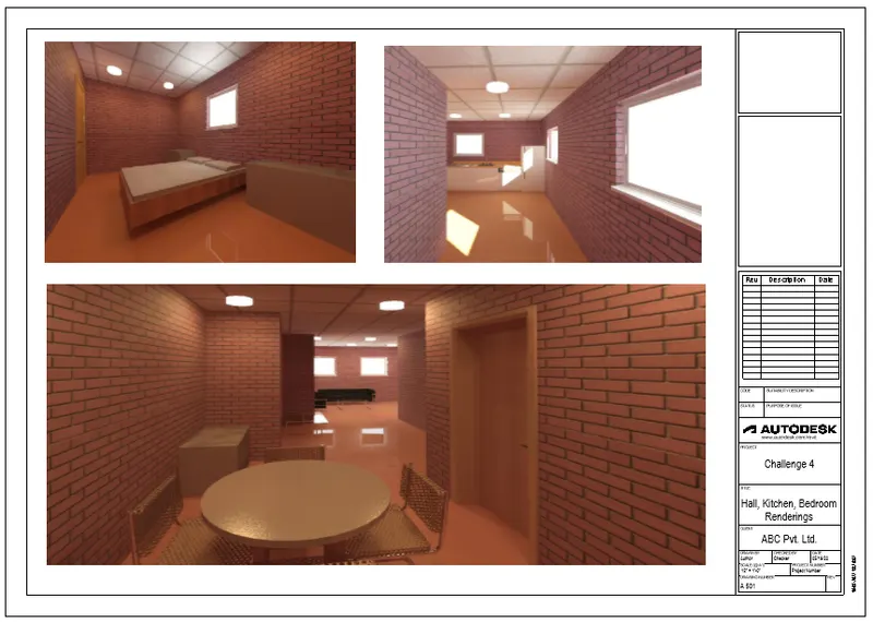
10)Create a camera-specific view or a 3D view in each room ( living, dining, bedroom). Based on the views create a new set of sheets starting A-501 (you can add as many sheets after, 502, 503.. n)to place the 3D view images. Produce the sheets as a part of project drafting.
- Go to view tab>Sheet (sheet composition)
- Select the sheet template to place the views
- Click place view>select the view in the list to place
- Double click the parameter to edit
Result: