Introduction to REVIT concepts
AIM: To create a new project and name the project appropriately.
Procedure:
step 1: OPEN REVIT.
click the window button and type revit and press revit.
once the revit is open the home page will fallows.
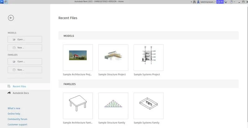
step :2
creating construction template.
click on new from home page.
- in the dialogue box click on construction template
- click on create new project
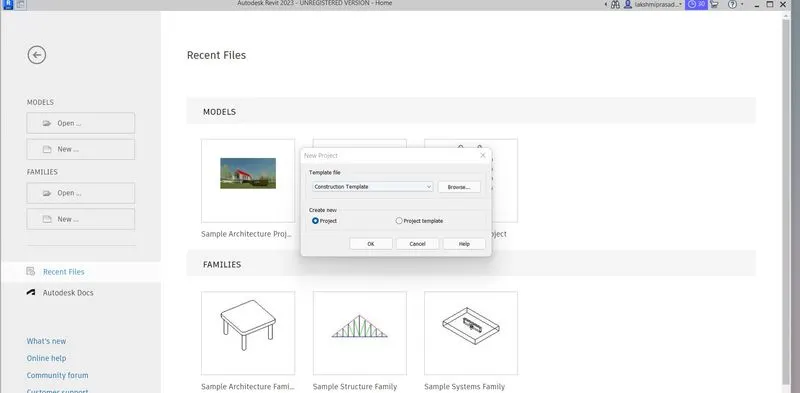
- click ok to open construction template.
- click on save button to open the dialogue box to set the file name.
Step 3:
creating Architectural template.
click on new from home page.
- in the dialogue box click on Archictectural template
- click on create new project
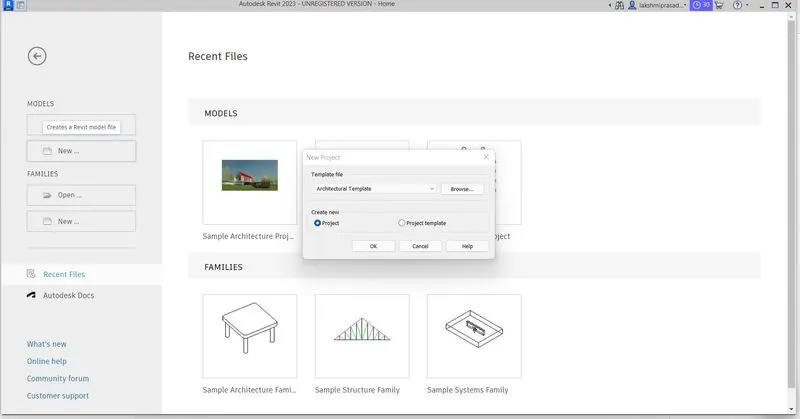
- click ok to open Architectural template.
- click on save button to open the dialogue box to set the file name.
step 4:
creating structural template:
lick on new from home page.
- in the dialogue box click on structural template
- click on create new project
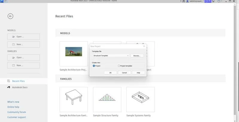
- click ok to open Structural template.
- click on save button to open the dialogue box to set the file name.
2. AIM: Save the new project file. Close and open using icons from file toolbar
step 1: OPEN REVIT.
click the window button and type revit and press revit.
once the revit is open the home page will fallows.
STEP 2: Saving any Drawing:
Draw any compoment in the drawing.
A wall boundary with randow dimensions is drawn.
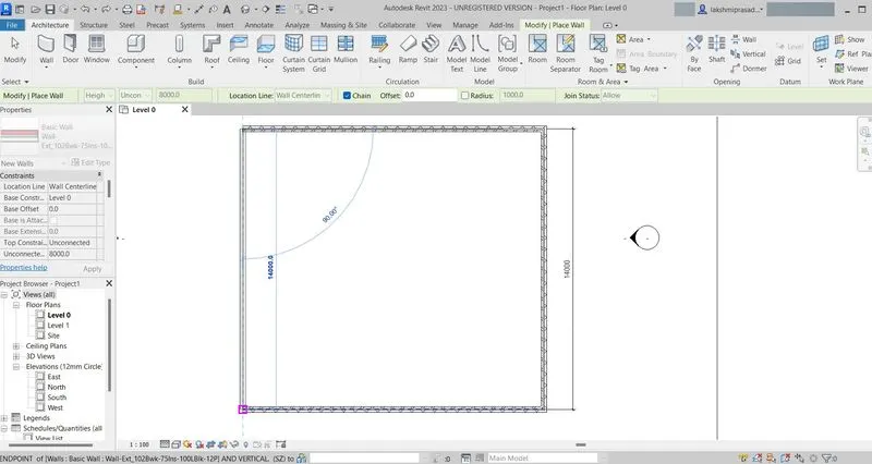
Save file by clicking save button on top left corner.close the file..
open any new template.
Go to file tab in top left corner.
click the open button in the file tab.
3) AIM :From the architecture/ structure toolbar familiarize with options to draw a wall. Create a rectangular layout of walls of about 40’-0” X 35’-0”
click on new from home page.
- in the dialogue box click on Archictectural template
- click on create new project
- click ok to open Architectural template.
- click on save button to open the dialogue box to set the file name.
Step :2
creating an architectural wall:
keep the wcursor on the wall on top left corner to view a description of the non -structural wall.
click the wall -architecrural button as shown
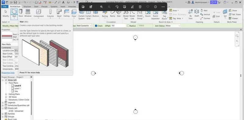
Specify the first point in the model space
specify the second point as 40'0"
specifythird point vertically downwads of length as 35'0"
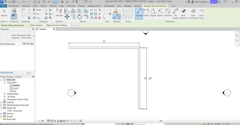
Step :2
creating an Structural wall:
keep the wcursor on the wall on top left corner to view a description of the non -structural wall.
click the wall -Structural button as shown
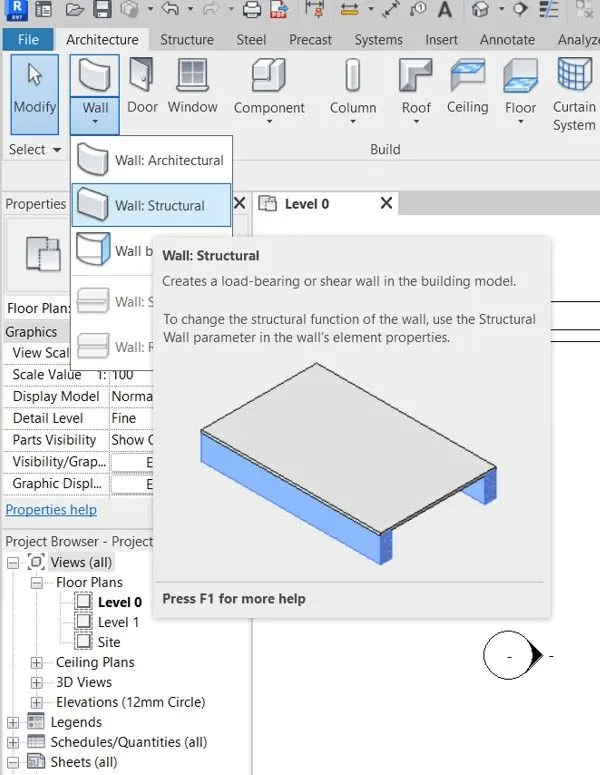
Specify the first point in the model space
specify the second point as 40'0"
specifythird point vertically downwads of length as 35'0".
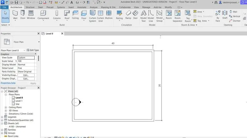
4.) Aim: TO annotate a drawing using alligned dimensions:
step:1 open revit
click windows button and type revit and open revit software.
step :2 open any drawing
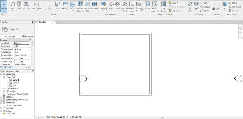
Step:3 Annotate.
click on alligned dimensions
select centre to centre point of edges.
5.) Aim: To change the wal type by using properties browser.
step:1 openRevit.
click windows button and type revit and open revit software.
step :2 open any drawing
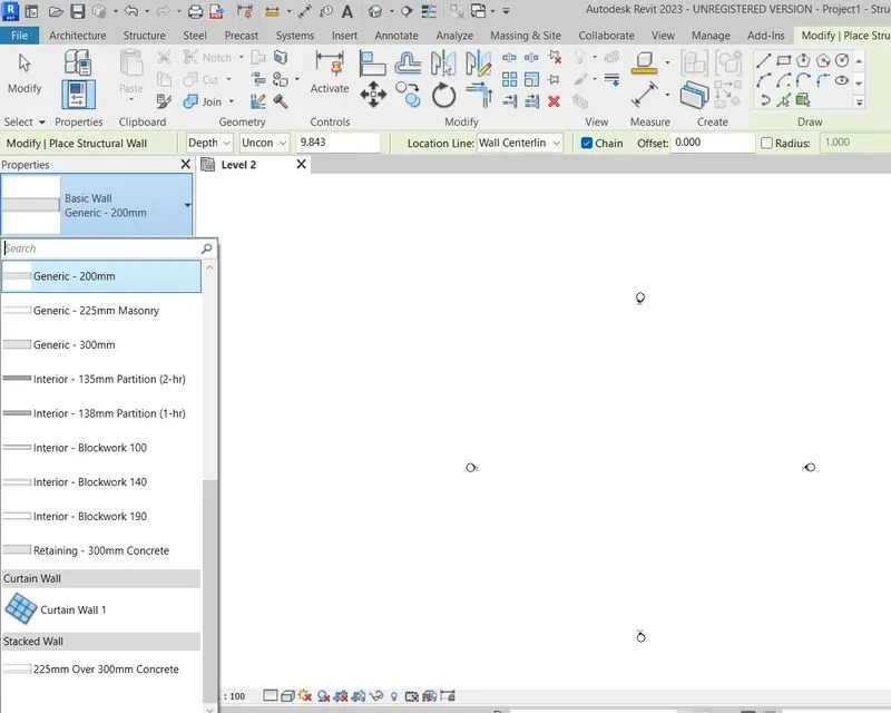
step : 3 change wall type
Go to project browser which is docked at bottom left ti view different walls.
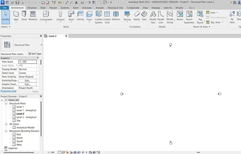
CLICK ON + on Families.
click on + walls to get different types of walls.
click on + of all wall types to get different sub.

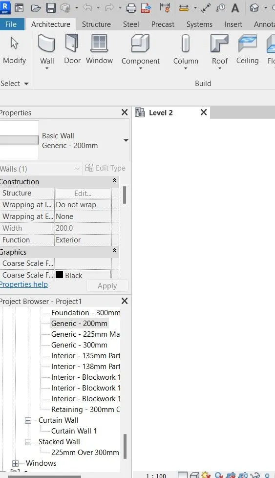
Go to properties browser and change wall type.
click on any wall drawn and right click to open properties browser.
6.) Create a 3D view from the view toolbar and save the view with the appropriate name
Aim: Create a 3D view from the view toolbar and save the view with the appropriate name .
step:1 openRevit.
click windows button and type revit and open revit software.
step :2 open any drawing
step:3 changing the view.
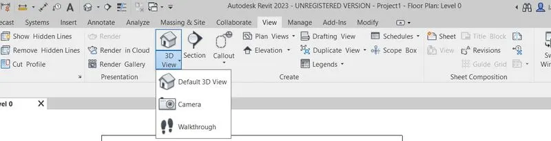
go to view tab.
under the create tool bar click on 3d view.
click on default 3d view.
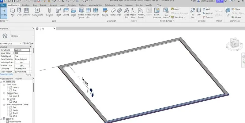
go to project browser.
under 3d view rename the current tab as 3D Isometric as shown below.
7) Navigate through the 3D model using the view cube. Orbit/pan through the model layout created
Aim:Navigate through the 3D model using the view cube. Orbit/pan through the model layout created.
step:1 openRevit.
click windows button and type revit and open revit software.
step :2 open any drawing
Step: 3 Navigation through view.
open the 3d view created above 3d isometric.
fron view change different views as required we can see.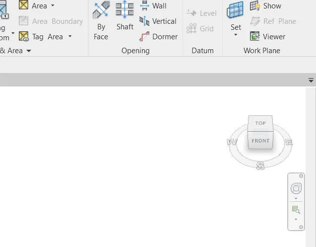
STEP:4 Orbit/Pan.
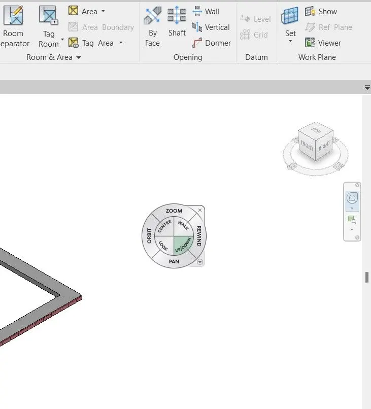
use a full navigationwheel we can orbit/pan as shown below.
8) Use the visibility settings option below to switch model to shaded, realistic, hidden lines options
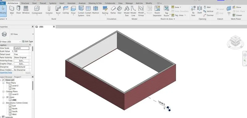
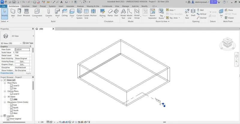
AIM: To create Use the visibility settings option below to switch model to shaded, realistic, hidden lines options.
step1 : open the revit.
select the browser to open revit software.
step :2 open any drawing.
step:3 change the visibility settings.
open the 3d view created above i.e., 3D ISOMETRIC.
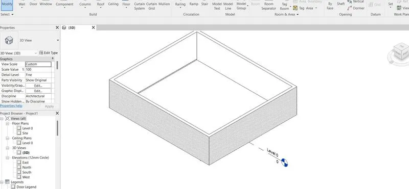
Go to bottom tool bar and click on visula settings as shown in figure
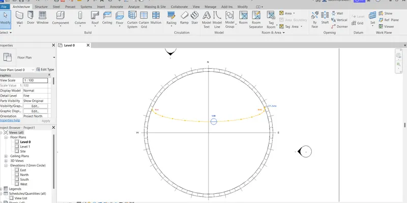
9.) Turn the sun path on and off to view shadings in the layout created
AIM: Turn the sun path on and off to view shadings in the layout created.
step:1 open revit and open drawing.
open any drawing in revit.
Creating a sun path:
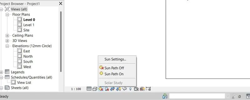
Go to bottom tool bar.
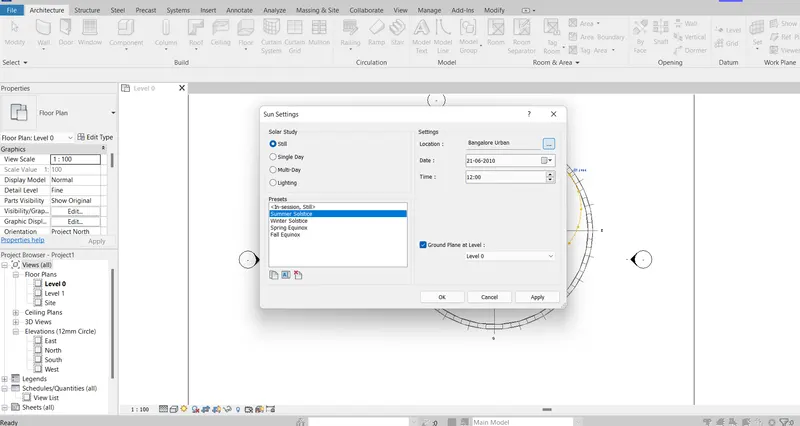
click on sun symbol to open sun settings.
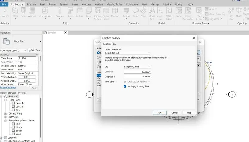
From dialogue box,click on... dotted lines to adjust the location.
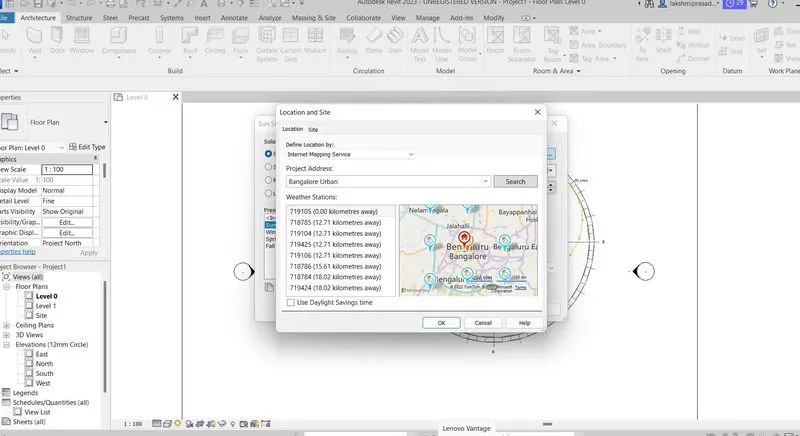
select the location as per requirement.
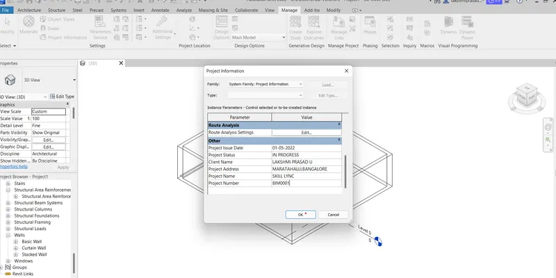
10.)Use the Manage toolbar to enter project settings, project name, and project issue date (choose according to your convenience
AIM:Use the Manage toolbar to enter project settings, project name, and project issue date (choose according to your convenience
To switch models view to shaded realistic and hidden lines options using visibility settings.
some of the major advantages of revit are as fallows.
1. parametric modelling
2.collaboration.
3.coordinatin
4.scheduling.
5.energy analysis.
6.rendering presentation.
7. construction documentation.
step:1 open revit and open drawing.
3d isometric view is also opened.
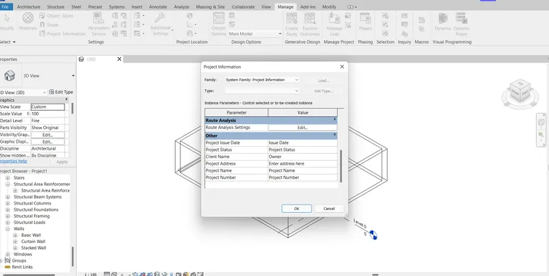
step:2 project settings.
go to manage tab.
click on project information.
dialougue box of.
RESULT:
11) What is the Analyze toolbar used in Revit? How it is beneficial for design and modeling
The analytical model, created automatically by Revit as you build the physical model, is used to perform the structural analysis and design. You export the analytical model to the analysis and design software.
- Analytical Model :A representation of the structural physical model consisting of analytical elements, geometry, material properties, and loads. It is created automatically while creating the physical model. You export the analytical model to the structural analysis and design software.
- Analytical model tools: it contains tools to adjust the analytical model, check for consistency reset the model and check memeber support in the tab.
- space and jonnes. the tool bar used to create space separators. space separators are drawn to separate the different room of the plan.
- reports & schedule: Heating & cooling load reports.
Duct pressure loss report.
pipe pressure and loss report.
panel schedule
schedule quantities
- check system.
- Energy optimazation
- Analyze tab energy
- Location
- create energy model
- generate
- optimize
- energy settings.
8.Route analysis.
9. structural analysis.
12.)What are the links that Revit supports to be linked to the model?
LINK REVIT:
Link One Model to Another.
- Open an existing model or start a new model. You will link another model into this model.
- Click Insert tab Link panel (Link Revit).
- In the Import/Link RVT dialog, select the model to link.
- For Positioning, specify the desired option. In most cases, you should select Auto - Origin to Origin.
- Click Open.
2.LINK IFC:
To use an IFC model as a reference for additional design work, link the IFC file to a Revit model. (Optional)
Before linking an IFC file, click File tab Open (IFC Options) and use the Import IFC Options dialog to do the following: Select a default Revit template to use for IFC files.
If a default template is not selected, the first template listed under File Locations in Revit Options will be used. Load an IFC class mapping file or manually assign Revit categories to IFC classes and types.
3.Link a CAD File :
- Open the Revit model.
- If you want the linked file to display only in a particular view, open that view.
- Click Insert tab Link panel (Link CAD).
- In the dialog, for Files of type, select the desired file type.
- Navigate to the folder that contains the file to link, and select the file.
- Specify the following options: If you want the linked file to display in the current view only, select Current view only.
- If you want the linked file to display in the current view only, select Current view only. If you do not...
- Click Open.
4Link Topography :
In Revit, link the topography to the current model as follows:
Specify coordinates for the building model. Define the model's survey point using grid (GIS) coordinates from the civil engineer. This strategy ensures accurate positioning of the model on the linked topography.
5. link DWF MARKUPS:
- in Revit LT, open a sheet view and export it to DWF by clicking File tab Export (DWF/DWFx). See Export to DWF.
- Use a DWF-compatible program (such as Autodesk® Design Review) to mark up the DWF file.
- Link the markups in Revit LT: Return to Revit LT. Click Insert tabLink panel (DWF Markup). In the Import/Link DWF File dialog, navigate to the marked-up...
6.link Decals
- In a Revit project, open a 2D view or a 3D orthographic view. The view must contain a flat or cylindrical surface on...
- Click Insert tab Link panel Decal drop-down (Place Decal). If no decals exist in the current project, the Decal Types...
- From the Type Selector, select the type of decal to place in the view.
- If you want to change the physical size of the decal, on the Options Bar, enter values for Width and Height. To maintain...
7. link point cloud:
- Open the Revit project.
- Click Insert tab Link panel (Point Cloud).
- Specify the file or files to link, as follows: For Look in, navigate to the location of the file (s). For Files of type,...
- For Look in, navigate to the location of the file (s).
- For Files of type, select one of the following options: Point Cloud Projects (
- .rcp): Pick an indexed point cloud..
13.)Why do you need the Collaborate tab in Revit? How it supports modeling and its efficiency
Collaborate tab is a cloud service provided in revit in which it allows variors revit users to work in the same project. with the help of Collaborate many users can work on the same working model, plan, designing etc.
Revit Cloud Worksharing is a cloud-based service that allows any Revit users inside or outside a network to collaborate on a Revit model. Bring multiple Revit models together to create a complete building model. Coordinate systems between Revit models can be reconciled to align their geometry.
Coordinate systems between Revit models can be reconciled to align their geometry. Use coordinates from another Revit model for positioning. Send coordinates of one Revit model to other Revit models for correct positioning. Control the way linked model geometry appears in views.
Account Administrators:
- Create projects & activate services.
- Add or remove members.
- Assign project admins.
- Assign further account admins.
Project Administrators:
- Add or remove members to project.
- Set permissions & visibility.
- Adjust project details.
After the BIM 360 subscription is activated, the Account Administrator receives an email with a get started link.