Internal Geneva Mechanism
AIM: To perform Multi-Body Dynamics using Solidworks on Internal Geneva Mechanism.
THEORY: The Geneva drive, often known as the Maltese cross, is a gear that converts continuous rotational motion into intermittent rotary motion. The rotating drive wheel normally has a pin that reaches into a slot in the other wheel (driven wheel) and moves it forward one step at a time.
Types of Geneva Mechanism
- External Geneva Mechanism:- The Geneva cross is connected to a cam drive outside in this sort of mechanism, which is more popular because it can be made smaller and tolerate higher mechanical pressures. During dwell, the driver grooves lock the driven wheel pins. The driver pin mates with the driven-wheel slot during movement. In an external Geneva drive, the angle at which the drive wheel must rotate to cause one step revolution of the driven wheel is always less than 180°.
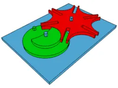
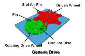
- Internal Geneva Mechanism:- A Geneva drive with internal storage is a variation on the idea. The Geneva cross and cam drive are connected internally in the closed box in this sort of mechanism. Both the drivers and the driven wheel spin in the same direction. Only one side of the axis of the internal drive's driving wheel can have a bearing. In an internal Geneva drive, the angle at which the drive wheel must rotate to cause one step revolution of the driven wheel is always larger than 180°.
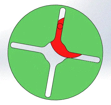
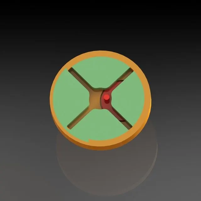
Working of Geneva Mechanism: A raised circular blocking disc on the drive wheel "locks" the rotating driven wheel in place between steps. The Geneva drive is most commonly configured with four slots on the client wheel, which advances the drive one step at a time (each step being 90 degrees) for each full rotation of the master wheel. The steered wheel advances by 360°/n every full rotation of the propeller wheel if it has n slots. Because the mechanism requires a lot of lubrication, it's usually housed in an oil capsule.
Applications of Geneva Mechanism:-
- In film movie projectors and movie cameras, the Geneva drive is used to draw the film through an exposure gate with periodic starts and stops. The film progresses frame by frame, with each frame remaining still in front of the lens for a portion of the frame cycle (usually 24 cycles per second) before rapidly accelerating, advancing, and decelerating for the remainder of the cycle. A Geneva drive generates the intermittent motion by activating a claw that engages sprocket holes in the film. In addition, the Geneva drive gives a precisely reproducible stopping position, which is crucial for eliminating jitter in subsequent photos.
- Modern film projectors may additionally include an electronically controlled indexing mechanism or a stepper motor that allows the film to be fast-forwarded. In mechanical timepieces, Geneva wheels in the shape of a driven wheel were also used.
- Other uses for the Geneva drive include plotter pen changing mechanisms, automated sampling devices, banknote counting machines, and a variety of indexable manufacturing equipment (such as the tool changers in CNC machines; the turrets of turret lathes, screw machines, and turret drills; some kinds of indexing heads and rotary tables; and so on). The Geneva mechanism is used by the Iron Ring Clock to generate intermittent motion to one of its rings.
- The Dawn mission framing camera was used to image the asteroid 4 Vesta in 2011 using a Geneva drive to change filters. It was chosen to ensure that at least one filter could be used if the mechanism failed.
Advantages of Geneva Mechanism:
- Of all the intermittent motion devices, the Geneva mechanism may be the simplest and least expensive.
They range in size from those used in instruments to those used in machine machines to index spindle carriers weighing several tonnes. - When compared to ratchets, they have superior motion curve features, but they have more jerk or sudden change in acceleration than better cam systems.
Disadvantages of Geneva Mechanism:
- The Geneva is a jerky mechanism that is not very adaptable.
- Once the number of dwells per revolution has been chosen, the dwell period to motion ratio is also determined.
With finite acceleration and deceleration, all Geneva acceleration curves begin and end.
- The 2-D drawing sheet required for making a 3-D modal of the Internal Geneva mechanism is as follows:-
For Driven Wheel
For Driver wheel
Objectives :
- Create 3D models for driver and driven wheels.
- Perform motion analysis by rotating the driver wheel at 10rpm.
- Obtain the following plots
- Contact force (between driving and the driven wheel) as a function of time.
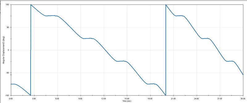
- Angular Displacement of the driven wheel.
- Compare the contact forces with and without "Precise contact"
- Show image for precise contact selection
- Export the results that you get to Excel and make the plots over there
Procedure :
We have done the various step to Perform the 3-D modeling and doing motion analysis of the Internal Geneva Mechanism as shown below:-
For making Driver wheel:
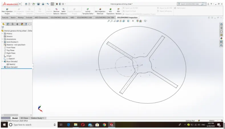
- First draw the above sketch by using tools like a circle, perimeter circle, line, construction geometry, offset, trim, circular pattern, point, and fillet. Make sure that the whole sketch is fully defined.
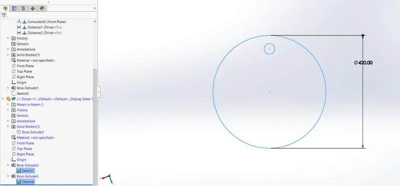
- And after that exit from the sketch and select the front plane and go to sketch and draw a circle of diameter 420mm from the point which is 160mm away from the intersection of the first sketch construction circle, construction line, and point and draw a circle of 40 mm diameter at that intersection point. The sketch of the driver part is shown below.
- Then exit from the sketch go-to feature, select extruded boss/base, select the outer circle, and extrude it to 20mm. and again go to extruded boss/base and select smaller circle, choose option surface/face/plane, and the select top surface of first extruded portion and extrude up to 40mm. Make sure that the merge result option is on. Hide the first sketch. And the extruded driver part is as shown below.
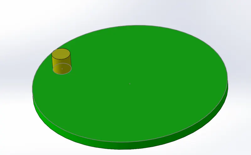
For making a driven wheel:
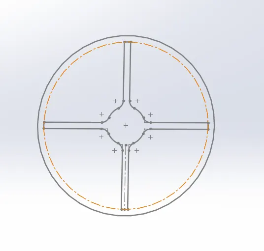
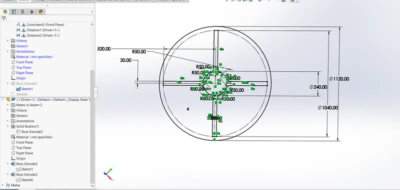
- First, draw the above sketch by using tools like circle, line, offset, circular pattern, and fillet. Make sure that the whole sketch is fully defined.
- Then exit from the sketch go-to feature and select extruded boss/base and select the sketch and extrude it to 40mm. And the extruded driver part is as shown below.
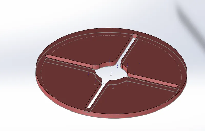
For assembly:
- Open SOLIDWORKS select assembly selects the driver and driven wheel, first select driven part open click on it then driver part open click on it. Go to the driven part to make it float. Then by using the mate tool to prepare the assembly various mate used in assembly are as follows:-
- Coincident - between the front plane of the driver front plane of the assembly.
- Coincident- between the axis of driver top plane of the assembly
- Coincident- between the axis of driver right plane of the assembly
- Coincident- between the axis of the driven right plane of the assembly
- Distance- between the front plane of the driven and front plane of assembly and distance is 20mm.
- Distance- between the axis of the driver and driven.
- The assembly obtained is as shown below:
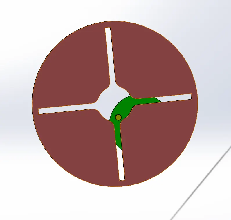
Motion analysis:
- Open the assembly and go to Solidworks add-ins and then click on solid works motion
- Now go to motion study and select the type of study as motion analysis.
- Go to the motor and select the axis of the driver and set the rpm.
- And then go to contact select the driver and driven component. And then select the material.
- And click on calculate to perform motion analysis.
- And at last, go to the result and plot option. We can see the various plots like Angular velocity vs time and contact force and time.
Plots:-
Contact force (between driving and the driven wheel) as a function of time at 10 rpm 60 FPS without precise contact, becomes smoother from the previous one.
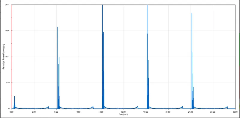
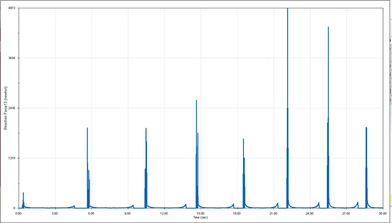
Contact force (between driving and the driven wheel) as a function of time at 10 rpm 60 FPS with precise contact, now the graph becomes much smoother than without precise contact.
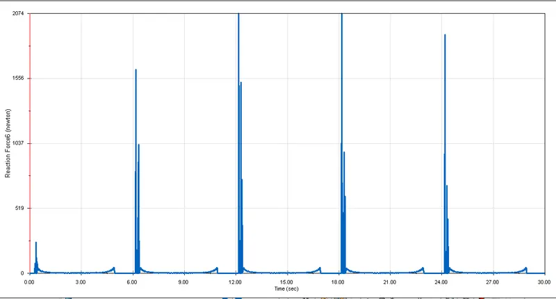
Contact force (between driving and the driven wheel) as a function of time at 20 rpm 120 FPS without precise contact.
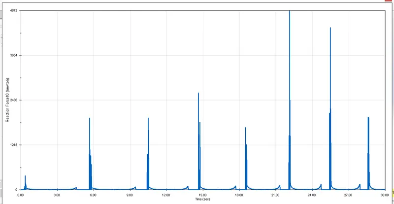
Contact force (between driving and the driven wheel) as a function of time at 20 rpm 120 FPS with precise contact, now the graph becomes much smoother than without precise contact.
Angular displacement vs time for driven at 10 rpm 60 FPS
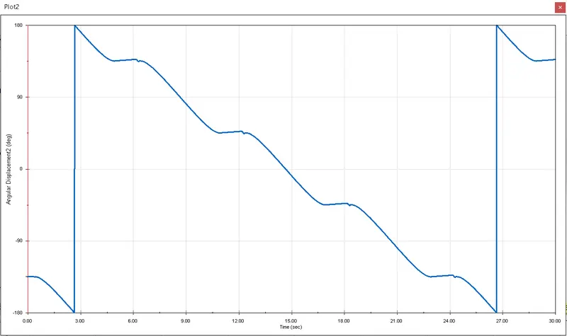
Angular displacement vs time for driven at 20 rpm 120 FPS
CONCLUSION:
- Creating sketches in Solidworks is easy when compared to other softwares.
- Constraining the sketches was also made handy.
- The motion study helps simulate the performance of the internal geneva mechanism and also gives an outline of the model for better output.