Internal Geneva Mechanism
AIM :-
To create an internal geneva mechanism and perform a motion study using Solidworks.
THEORY :-
Geneva Mechanism or Maltese Cross is a gear mechanism that translates a continuous rotary movement into intermittent rotary motion. The rotating driver wheel is equipped with a pin that reaches into a slot located in the driven wheel that advances it by one step at a time. The driver wheel also has an elevated circular blocking disc that locks the rotating driven wheel in position between steps.
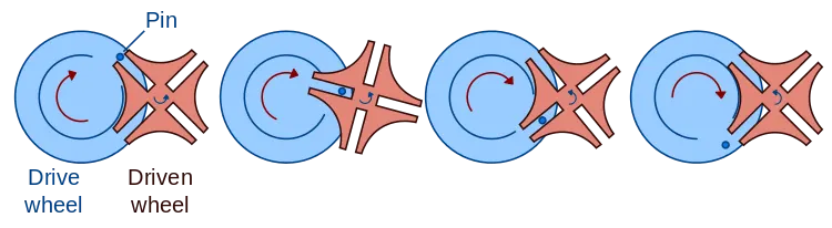
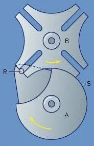
In the figure shown below, the driver A carries a pin R that fits in the four radial slots in the follower B. Between the slots there are four concave surfaces that fit the surface S on the driver and serve to keep the follower from rotating when they are fully engaged. In the position shown, the pin is entering one of the slots, and on further rotation of the driver, it will move into the slot and rotate the follower through 90°. After the pin leaves the slot, the driver will rotate through 270° while the follower dwells, that is it stands still.
There are three types of geneva mechanisms and they are,
- External geneva mechanism.
- Internal geneva mechanism.
- Spherical geneva mechanism.
In this challenge an internal geneva mechanism is modelled and it's simulation is conducted.
SOLIDWORKS MODEL OF THE GENEVA MECHANISM :-
1. Driver Component,
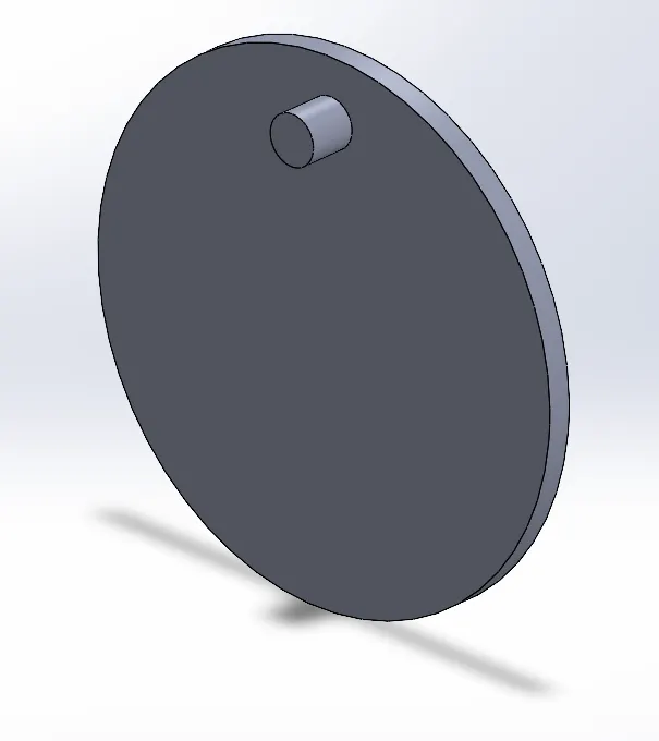
- A circle of diameter 420 mm is sketched and the sketch is extruded by 20 mm.
- To create the pin, front face of the base is selected and a smaller circle is sketched on it with a diameter of 40 mm at a distance of 160 mm from the origin of the plane. The center of the circle and the origin of the plane are made vertical to each other to fully constrain the circle. It is then extruded by 40 mm.
2. Driven Component,
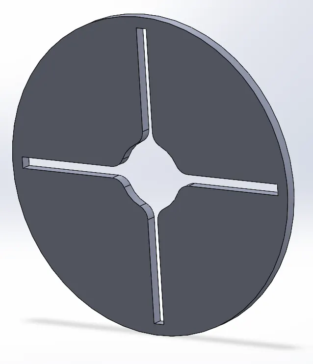
- A circle of 1120 mm diameter is sketched and extruded by 40 mm to create the base.
- Using the front face of the base, the slots are sketched.
- Two circles are created with the smaller circle having dimension of 240 mm diameter and the larger circle having 1040 mm diameter. The larger circle is selected as construction geometry.
- Using the line tool, a line is drawn from the center of the smaller circle to the center of the larger circle and is converted into a construction line.
- Then three lines are drawn which connect between the larger and smaller circle and a distance of 20 mm is provided from the construction line.
- Using the circular sketch pattern, the rectangular figure is then mirrored equally on all four sides and the with the trim entities option the section between the rectangles and the smaller circle are trimmed.
- Fillets of radius 50 mm are added to the edges of the circle and rectangles using the fillet tool.
- The sketch is cut using the extrude cut option by 40 mm.
Assembly of the Parts,
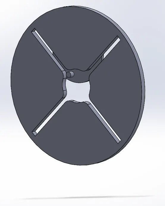
- First the driver component is imported and then the driven component. The driver component is selected to float for it to move.
- Coincident mates between the front, top and right planes of the driver component and assembly are created to fully constrain the component to only rotate and not move linearly.
- Coincident mate between the driven component and right plane of the assembly is created.
- Distance mate between the front planes of the driver and driven component is created to prevent them from colliding during the simulation.
- Distance mate between the center axes of driver and driven component is created to allow the pin to enter the slots without any collision.
OUTPUT :-
Motion study simulation is conducted for 3 cases and the plots of contact force, angular displacement and angular velocity are obtained.
1. Driver Wheel Rotated at 10 rpm Without Precise Contact and Then With Precise Contact,
Rotary input is provided to the driver wheel and a speed of 10 rpm is selected. The driver wheel and driven wheel are selected as contact surfaces and the motion analysis is conducted. By default the motion analysis conducted without precise contact enabled. Two plots are obtained which are contact forces between the driver and driven wheels, and the angular displacement of the driven wheel.
Contact force plot is given below,
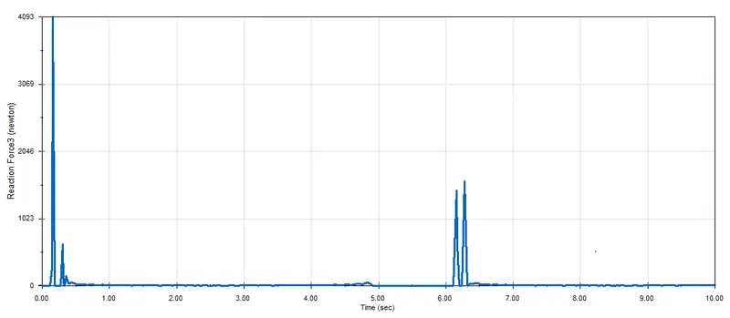
The rise in forces indicated that the pin comes in contact with the slot and moves along the slot to rotate the driven wheel. Once a full rotation is completed, the contact forces drop to 0 and again increases for the second cycle.
The angular displacement of the driven wheel without precise contact is given below,
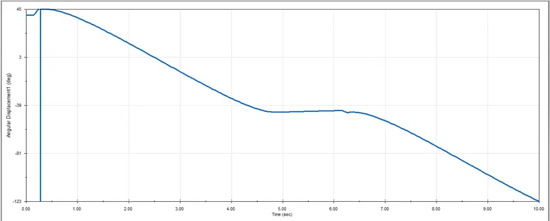
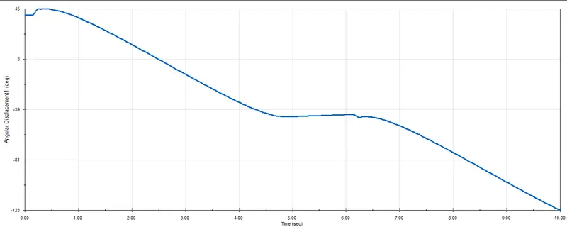
The angular displacement is initially high as the pin comes in contact with the slot and starts to decrease as the driven wheel completes a rotation. The vertical line at the beginning is due to precise contact disabled, which shows the jerk that occurs when the pin comes in contact with the slot. Upon enabling precise contact the plot becomes much smoother and the vertical line is eliminated as shown in the plot below,
2. Driver Wheel Rotated at 10 rpm and Increasing the Frame Rate to 60 FPS,
By default all simulations are run at 25 fps. In order to have a smoother simulation and get more precise values the frame rates are increased. For this case the fps is increased to 60 while keeping the motor rpm the same which is 10 rpm. The angular velocity of the driver wheel is plotted which is shown below,
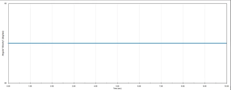
The angular velocity of the driver wheel is constant at 60 deg/s when it rotates at 10 rpm.
3. Driver Wheel is Rotated at 20 rpm at 120 Frames Per Second,
The motor speed is increased to 20 rpm and the frame rate is increased to 120 fps. The angular velocity of the driver wheel is plotted.
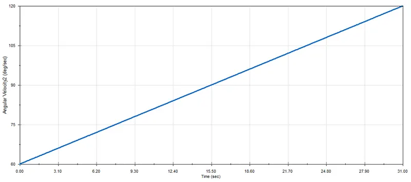
Here the angular velocity is a linear curve with an increase of 60 deg/s. The angular velocity curve can be made constant by increasing the frame rate further to get a more precise result.
CONCLUSION :-
Motion study of an internal geneva mechanism is conducted at different motor speeds and frame rates and the plots of contact force, angular displacement of the driven wheel and angular velocity of the driver wheel are plotted and analysed.