Induction Motor Characteristics II
1) Discuss about the equivalent circuit network of induction motor MATLAB model.
Working principle:
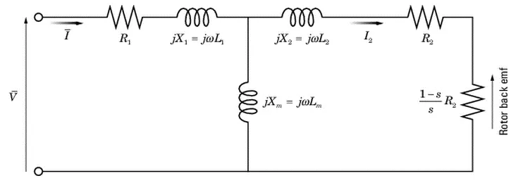
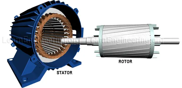
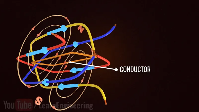
An induction motor (IM) consists of a stationary component called a stator and a rotary component called the rotor. The stator consists of three coil windings to which 3-phase AC power supply is given. With variations in AC supply frequency, a rotating magnetic field (also referred to as flux) is generated and interaction with the rotor circuit (RHS of the model) is triggered through electromagnetic induction. This induces an EMF (rotor back EMF in the figure) and therefore a current in the rotor circuit (seen as `I_2` in the figure). The rotor is now a current carrying conductor in a rotating magnetic field (refer to figure below), and so it experiences an electromagnetic force, producing a torque.
The magnetizing inductance `L_m` is required in the air gap between the stator and rotor circuits (refer to model above), acting as a boundary. Once the stator generates a rotating magnetic field, it needs to cross the air gap to interact with the rotor to complete the process of producing a torque.
Operation:
The speed with which the magnetic field rotates is called the synchronous speed (`omega_(ms)`). The speed with which the rotor rotates, `omega_m` , is slower than `omega_(ms)` because of the boundary that the stator needs to cross to interact with the rotor. In the process, the losses through RLC components account for this reduction from `omega_(ms)` to `omega_m`. This allows the rotor to constantly cut the magnetic field, and hence induce the current and EMF to sustain the torque the motor is eventually producing. The synchronous speed is determined by the frequency of the AC supply, and we can say that both `omega_(ms) and omega_m` are proportional to this frequency.
This difference between synchronous and rotor speed is known as slip:
`S=(omega_(ms)-omega_m)/omega_(ms)`
where:
0 < S < 1
If the slip is 0, it means that no torque is produced, since rotor and magnetic field are rotating at the same speed, thereby enabling no interaction or cutting of the field lines. If the slip is 1, this refers to the starting torque and is the highest torque that can be produced by the IM.
The torque that is produced by the motor can be expressed as:
`T=(3/omega_(ms))(V^2.R_2^'/s)/((R_1+R_2^'/s)^2+(X_1+X_2^')^2`
where:
`R_1` - stator resistance
`R_2^'` - rotor resistance
`X_1` - stator inductance
`X_2^'` - rotor inductance
V - supply voltage
2) 3 phase, 50 Hz induction motor, represented by equivalent circuit constants X1 = X2 = 0.1 ohm and R1 = R2 = 0.2 ohm is operated at half of rated voltage and frequency. Calculate the ratio of starting torque at half voltage & frequency to rated values.
`T=(3/omega_(ms))(V^2.R_2^'/s)/((R_1+R_2^'/s)^2+(X_1+X_2^')^2`
`omega_(ms)=(120f)/p`
`T_(s_1)/T_(s_2)=(((3p)/(120(1/2f)))(((1/2V)^2.R_2^'/s)/((R_1+R_2^'/s)^2+(X_1+X_2^')^2)))/(((3p)/(120f))(((V)^2.R_2^'/s)/((R_1+R_2^'/s)^2+(X_1+X_2^')^2)))`
`T_(s_1)/T_(s_2)=((1/4V^2)/(60f))/((V^2)/(120f))=1/2`
3) Make a MATLAB script file which will plot speed torque characteristics for frequency control method.
The frequency control method is one of the ways to control the speed of an induction motor. Varying the frequency of the DC supply will directly affect the speed of the rotating magnetic field, which in turn will affect the speed of the rotor and therefore the induction motor.
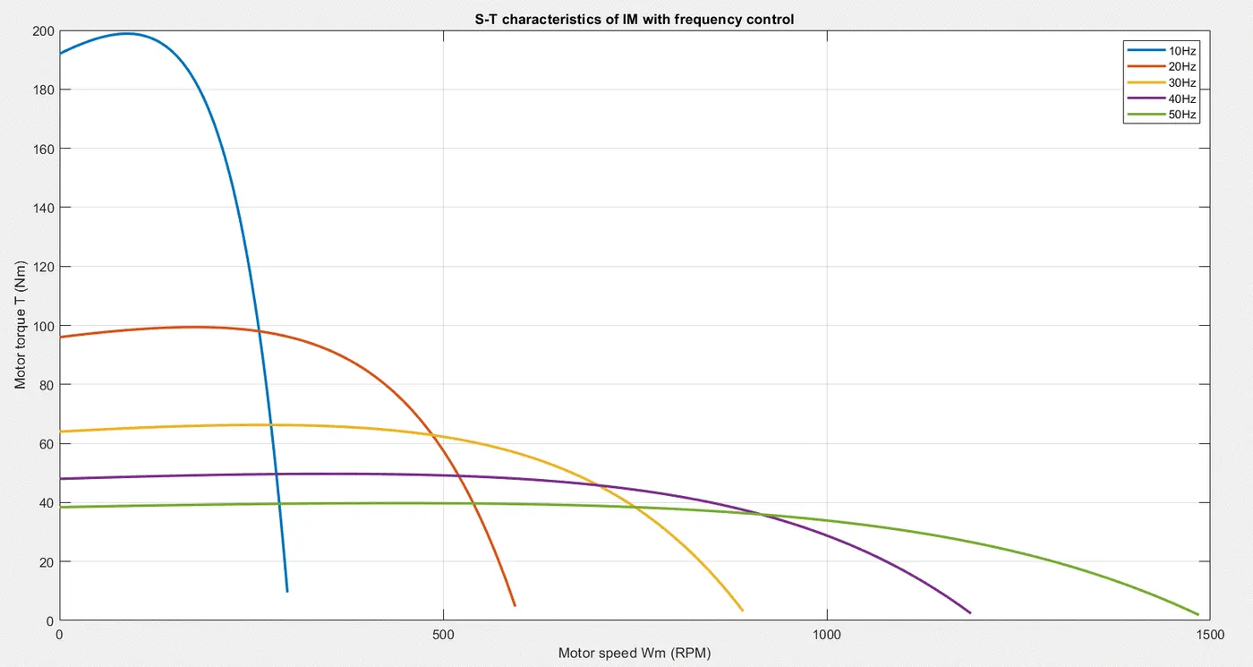
Different supply frequencies will result in different synchronous speeds, and thus the rotational speed of the rotor will be different too. This would correspond to different slip values, and finally this would mean a different torque for every frequency. All of this can also be deduced by examining the speed-torque equation of an IM (refer to Q2).
Code:
%---------Speed-torque relationship of IM-----------

clear all; close all; clc

%-----constants-----
V = 240/sqrt(3); %3 phase
R1 = 0.2;
R2 = 0.2;
X1 = 0.1;
X2 = 0.1;
poles = 4;
%-------------------
slip = linspace(0,1,100);
freq = linspace(10,50,5); %10 - 50Hz

for i = 1:length(freq)
    Wms(i) = 120*freq(i)/poles; %synchronous speed
    for j = 1:length(slip)
        T(j) = (3/Wms(i))*((V^2*R2/slip(j))/((R1+R2/slip(j))^2 + (X1+X2)^2)); %S-T eqn
        Wm(j) = Wms(i)*(1-slip(j)); %motor speed
    end
    plot(Wm,T,'linew',2)
    hold on
end

title('S-T characteristics of IM with frequency control')
xlabel('Motor speed Wm (RPM)')
ylabel('Motor torque T (Nm)')
grid on
legend('10Hz','20Hz','30Hz','40Hz','50Hz')
Output:
4) Explain in brief about operation of BLDC motor.
Conventional brush-type DC motors were constructed with commutator and slip rings. The brush contact with the commutator experiences wear and tear over time, produced noise, and caused sparking due to high friction. This made them inappropriate for applications where high durability and reliability were required, and thus came Brushless DC motors (BLDC).
Operation:
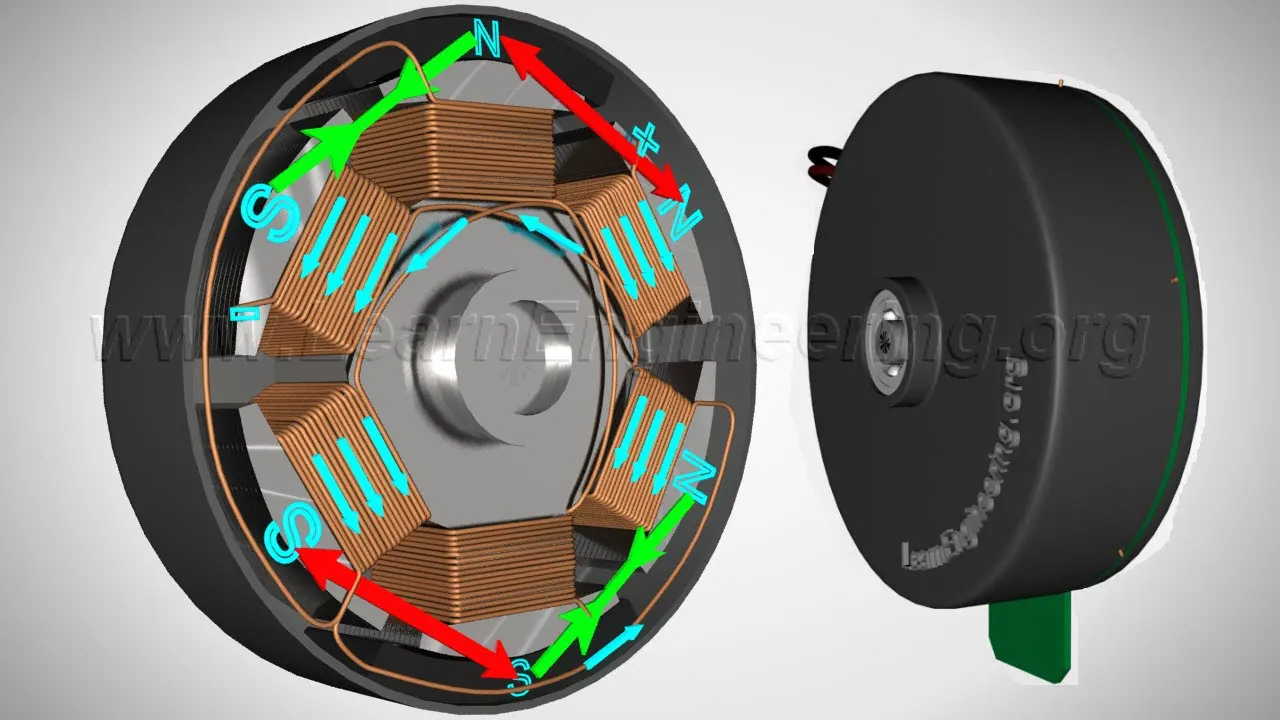
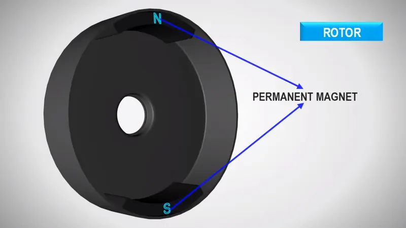
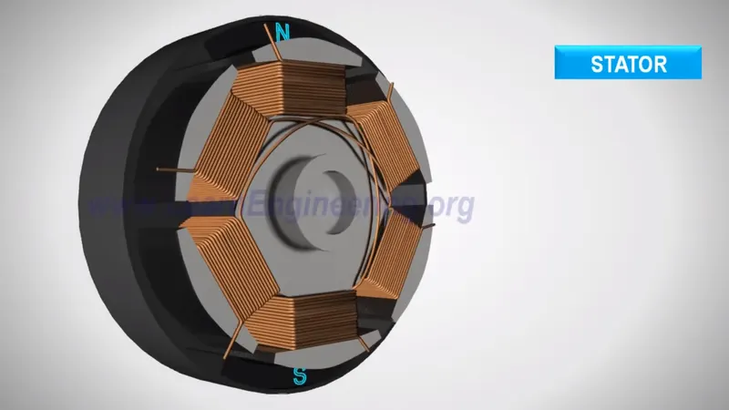
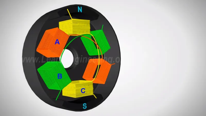
The BLDC consists of a permanent magnet as part of the rotor, and coil windings (3 sets of 2 windings each) as part of the stator, which can be referred to as A, B, and C, as depicted in the figure below. BLDC motors can be of outrunner and inrunner type. In the outrunner type the rotor surrounds the stator, and vice versa for the inrunner type.
A DC supply is given to one set of coil windings (A for instance), energizing them and making them an electromagnet in a magnetic arena. The operation is a simple interaction between the permanent magnet and the electromagnet, which exerts a force on the rotor, thereby rotating it to produce a torque.
Working principle:
Initially, as set A is supplied with DC current, the permanent magnets are kept in line with coil set C. As soon as coil set A starts acting like an electromagent, the N pole and S pole of the rotor are attracted to S pole and N pole of the coil winding, respectively. When the rotor arrives at set A, coil set B is energized. When the rotor arrives at set B, coil set C is energized. This way the rotor keeps on following the coils and rotating. At this point, the rotor has made a 180 degree rotation from its initial position. To keep it going in the same direction, the magnetic polarities are reversed (refer to first and third figures below to see the reverse in polarities).
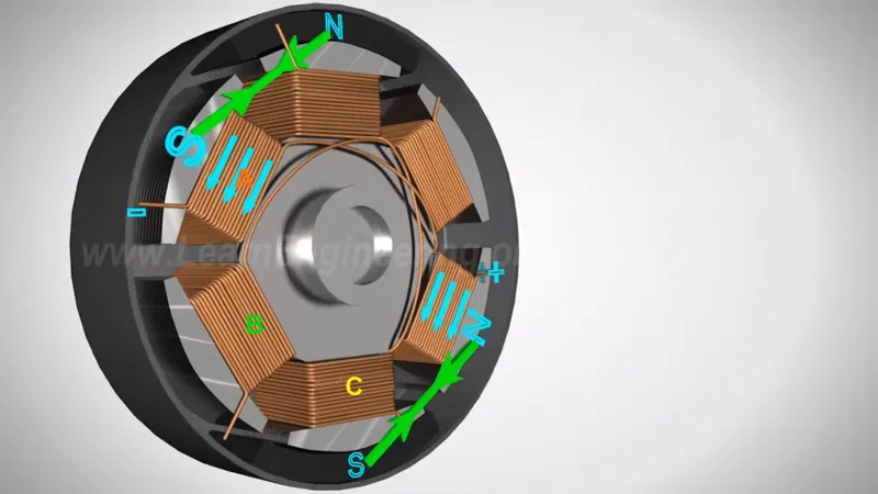
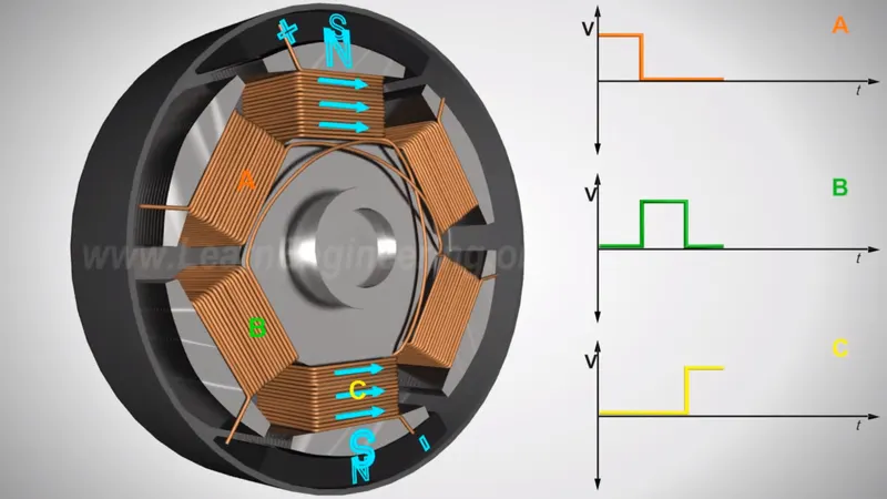
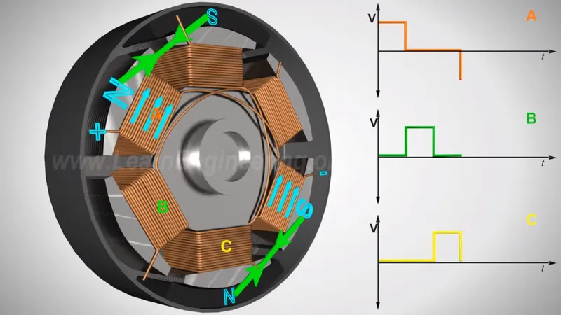
The operation of a BLDC motor is similar to that of an IM in the sense that there is a slip between the stator and the rotor. Without this created slip, only starting torque will be available and sustaining constant torque wouldn't be possible. The DC supply to stator windings needs to be quicker than the rotation of the rotor permanent magnets to sustain the interaction happening.
There is however a drawback of this operation. At any instant, only one set of coil is energized while the other two are inactive. This significantly reduces the potential power output of the motor. This can be overcome by energizing the not just the coil in front of the rotor's position, but also the coil behind it (refer to the figure below). The polarity should be reversed for the coil behind though, so that it creates a repelling force with the permanent magnet, while the permanent magnets are already attracted to the coil in front. This kind of dual setup will give the permanent magnet more thrust to move forward, hence increasing the speed of rotation, the torque, and thus the power output.