Independent Research Project
PROJECT: FATIGUE OF THE OIL FILTER HOUSING
TITLE: REPORT ON THE OIL FILTER HOUSING (FE Analysis)
|
Date of Issue |
27/09/2022 |
03/10/2022 |
13/10/2022 |
|
Total No of Pages including cover page |
18 |
18 |
20 |
|
Name |
Date |
|
|
Prepared by |
Mr. Deepak Kumar |
29-Jul-2023 |
TABLE OF CONTENT
|
Sr. No. |
Content |
Page |
|
1 |
Introduction |
4 |
|
2 |
Geometry and nomenclature |
5 |
|
3 |
Material data |
6 |
|
4 |
FEA workflow |
7 |
|
5 |
Meshed model |
8 |
|
6 |
Simulation setup-loads and constraints |
9 |
|
7 |
Results |
11 |
|
8 |
Fatigue life cycle calculation |
16 |
|
9 |
List of reference documents |
20 |
-
INTRODUCTION
This document reports on the work undertaken to design oil filter housing by the FEA technique. The oil filter housing is subjected to a very huge pressure load and that can induce very high structural stresses in the assembly. Hence fatigue life estimation is required to establish the lifetime of this equipment.
Scope of work:
-
Structural analysis of oil filter housing against pressure load from 0 to 380 bar
-
Fatigue life cycle calculation at 380 bar pressure loads
Analysis considerations:
-
A tiny geometrical feature like fillets or chamfers has been removed.
-
All material properties are considered at room temperature.
-
GEOMETRY & NOMENCLATURE
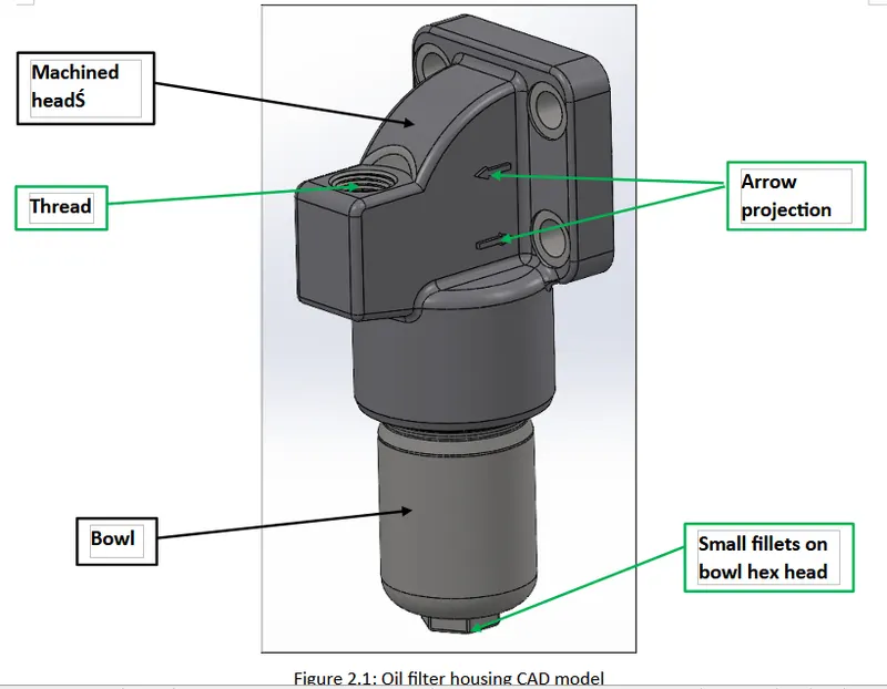
As shown in figure 2.1, the oil filter housing assembly consists of a machined head and bowl. As highlighted by green arrows, small fillets on the bowl hex head, arrow projection, and threads have been removed. Internal threads on the machined head and external threads on the bowl used to make the assembly are considered in the simulation.
-
MATERIAL DATA
|
Component:- Machined head |
|||
|
Material:- EN-GJS-400-15 |
|||
|
Property |
Value |
Unit |
Reference |
|
Modulus of elasticity |
169 |
GPa |
DIN EN1563-Table E.1 |
|
Density |
7100 |
Kg/m3 |
|
|
Poisson’s ratio |
0.275 |
- |
|
|
Component:- Bowl |
|||
|
Material:- EN19 |
|||
|
Property |
Value |
Unit |
Reference |
|
Modulus of elasticity |
190.3 |
GPa |
B.S. 970-The mechanical & physical properties of the British standard EN Steels, Page 365 |
|
Density |
7850 |
Kg/m3 |
|
|
Poisson’s ratio |
0.279 |
- |
|
-
FEA WORKFLOW
Geometry cleanup and meshing

Material creation and assignment
Loads and constraints application
Solution processing
Result extraction and fatigue life cycle calculation
-
MESHED MODEL
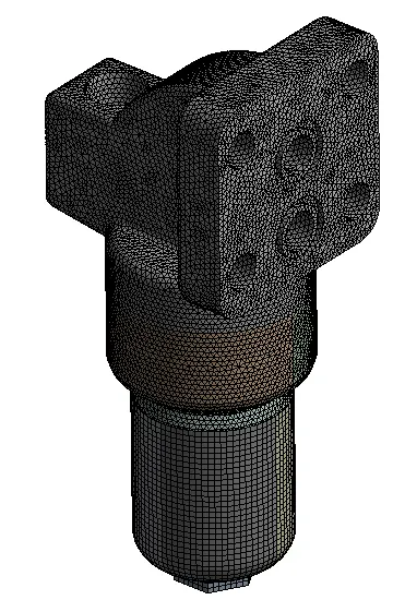
Figure 5.1: Meshed model
-
SIMULATION SETUP-LOADS AND CONSTRAINTS
Constraints:-
-
Geometry is constrained at machined head end flange bolt holes- Ref. figure 6.1
Loads:-
-
Internal pressure from 0 to 380 bar- Ref. figure 6.3
-
Self-weight of oil filter housing assembly- Ref. figure 6.2
-
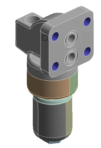
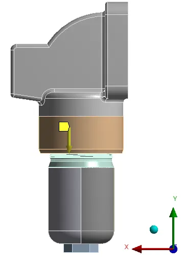
Figure 6.1: Fixed support Figure 6.2: Self-weight
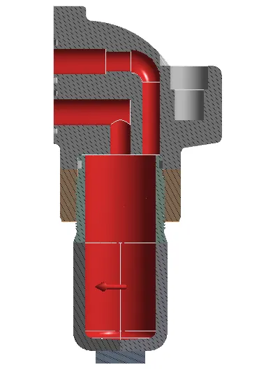
Figure 6.3: Internal pressure (0 to 380 bar)
7. RESULTS
The Deformation and stress plots shown below are at the pressure level of 380 bar.
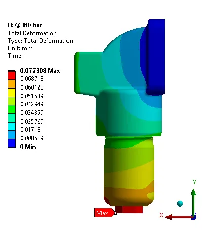
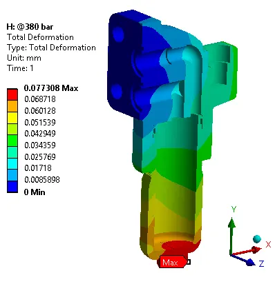
Figure 7.1: Deformation plot
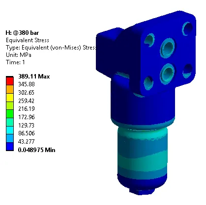
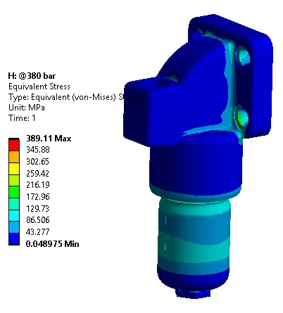
Figure 7.2: Assembly Von Mises Stress Plot (front and back views)
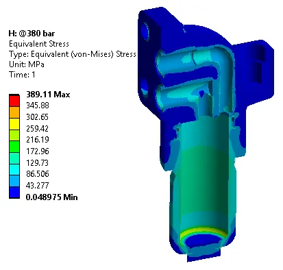
Figure 7.3: Assembly Von Mises Stress Plot (section view)
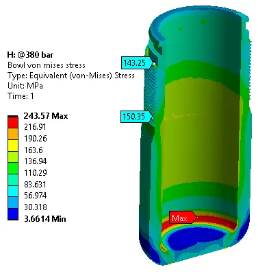
Figure 7.4: Bowl Von Mises Stress Plot (section view)
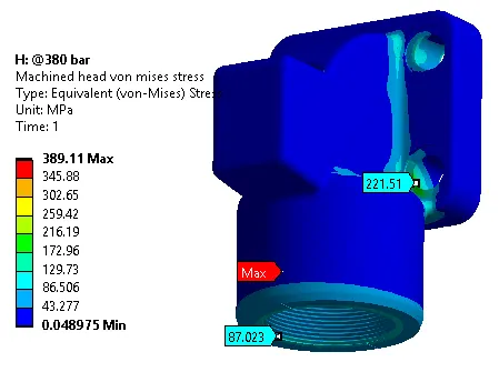
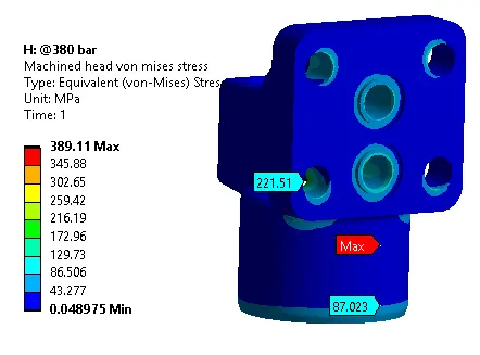
Figure 7.5: Machined head Von Mises Stress Plot (front and back views)
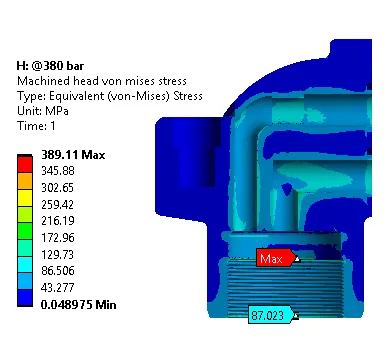

Figure 7.6: Machined head Von Mises Stress Plot (section view)
For life cycle qualification purposes, uniformly distributed Von Mises Stress at thread root has been considered instead of local stress singularity as shown in above figure 7.6
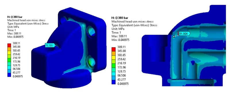
Figure 7.8: Machined head Von-Mises Stress on inner and outer surfaces (probe at critical location)
8. FATIGUE LIFE CYCLE CALCULATION
Fatigue life calculation has been done at 380 bar pressure level.
8.1 Machined head life cycle evaluation
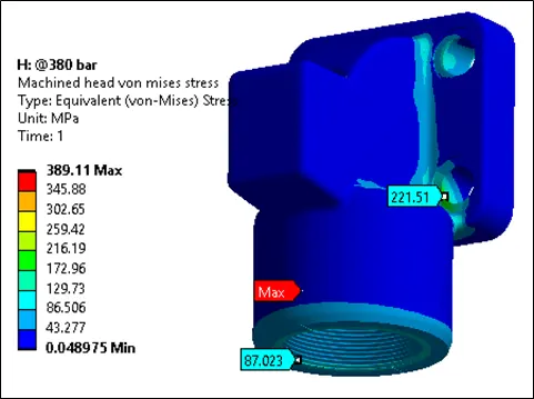
Figure 8.1: Machined head critical locations for fatigue life evaluation
Table 8.1: Machined head fatigue life cycles
|
Critical location on the machined head |
Location No. |
Von Mises Stress (MPa) |
Fatigue life cycles |
|
Bolt hole |
1 |
221.51 |
3.4 X 10⁵ |
|
Thread root |
2 |
87.02 |
106 |
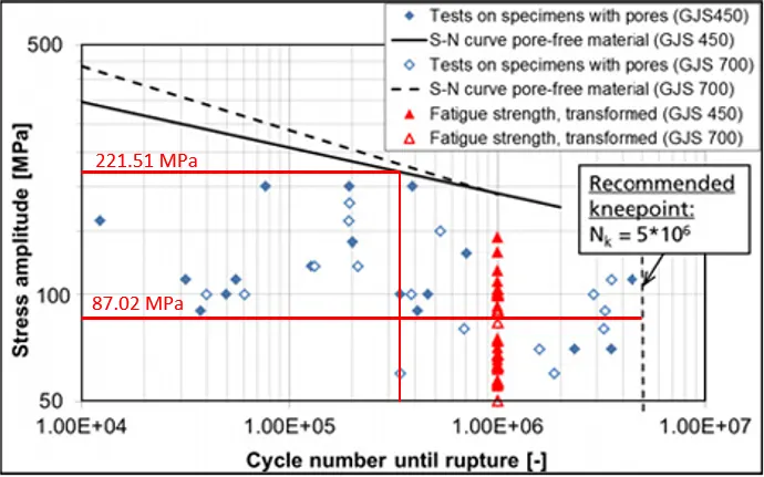
Figure 8.2: S-N curve for machined head material (pore-free state considered)
Conclusion-
At a level of 190 MPa and below, the fatigue life cycles are coming to 106.
The factor of safety with respect to 190 MPa stress level is calculated as follows:-
FOS (at location 1) - 190/221.51= 0.85
FOS (at location 2) - 190/87.02= 2.18
Calculated FOS is based on without considering the below points.
-
Location 1 Stresses are high due to the fixing support considered in FEA. In actual condition, the bolt pretension is applied to fasten the components therefore FOS will increase as compared to Analysis.
-
Life cycle is calculated based on the cyclic load SN curve, but the loading in the oil filter is incremental from 0 to 380 bar. FOS will increase if we use the SN curve based on incremental loading.
8.2 Bowl life cycle evaluation
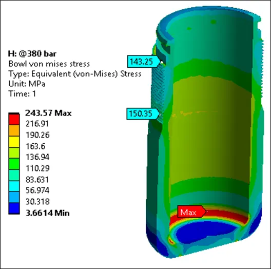
Figure 8.3: Bowl critical locations for fatigue life evaluation
Table 8.2: Bowl fatigue life cycles
|
Critical location on the machined head |
Location No. |
Von Mises Stress (MPa) |
Fatigue life cycles |
|
Fillet at the bottom of the bowl |
1 |
243.57 |
106 |
|
Thread root |
2 |
150.35 |
106 |
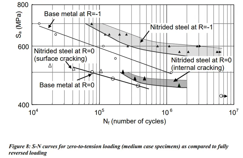
Figure 8.4: S-N curve for bowl material (Base Metal at R=0 curve)
Conclusion-
Stresses induced in the bowl are lower than the 400 MPa stress level, hence as shown in figure 8.4 life cycles come around 106.
The factor of safety with respect to 400 MPa stress level is calculated as follows:-
FOS (at location 1) - 400/243.57= 1.64
FOS (at location 2) - 400/150.35= 2.66
Calculated FOS is based on without considering the below points.
-
Life cycle is calculated based on the cyclic load SN curve, but the loading in the oil filter is incremental from 0 to 380 bar. FOS will increase if we use the SN curve based on incremental loading.
Summary of Results:
|
Components |
Location |
380 Bar Results |
|
|
Stress (MPa) |
FOS |
||
|
Head |
Location 1 |
221.51 |
0.85 |
|
Location 2 |
87.02 |
2.18 |
|
|
Bowl |
Location 1 |
243.57 |
1.64 |
|
Location 2 |
150.35 |
2.66 |
|
Note: 250 Bar Pressure - stress is derived from the linearization of the result.
9. LIST OF REFERENCE DOCUMENTS
|
Sr.No. |
Document title |
|
1 |
DIN EN1563 |
|
2 |
B.S. 970-The mechanical & physical properties of the British standard EN Steels |
|
3 |
Journal paper: Axial fatigue of a gas nitride quenched and tempered AISI4140/EN19 Steel |