Identification of Cracks
AIM 1 : What is the mode of failure or damage of the beams in the figure BELOW? Are the damages repairable? Elaborate
a) b) c)
EXPLAINATION 1 :
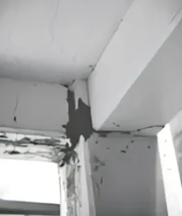
a) OBSERVATIONS:
- The Concrete gets damaged/broken and reinforcement is visible at the bottom of the beam.
- The is concrete damaged beyond the reinforcement indicates the segregation
- Cracks developed in the bottom and gradually increased towards the top.
- The top portion of the beam is not exposed due to cover from the slab projection so, it looks safe and has no major issue/severe issue on top of the beam.
- The pressure on the beam is more than its yielding point on the bottom supports but the reinforcement is still active at the support's top so there is no crack on top of the beam.
CONCLUSIONS:
- The bottom reinforcement of the beam lost there an elastic limit, so it's impossible to repair the bottom crack. This is a kind of flexural failure.
- Bottom reinforcement is not sufficient to resist the tension in beam and the top reinforcement resists the slab due to the concrete
- At the time of the earthquake, the beams get in the n tension zone and the structure feels in compression due to the stress reversal support at the top.
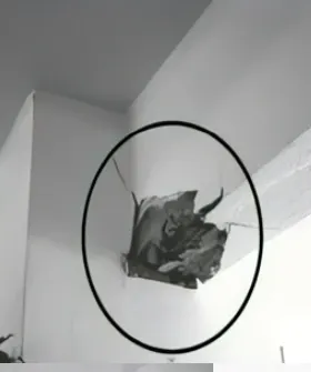
b) OBSERVATIONS:
- The cracks developed in column-beam corners.
- It is observed wider crack has developed through the column-beam joint.
- The beam has separated from the column.
- The picture shows, the concrete has not been crushed, there a crack developed.
CONCLUSIONS:
- The reinforcement of the beam is not sufficient to anchor the longitudinal rebars of the column, may be due to insufficient development length of the rebar.
- The lateral movement cannot be satisfied due to the insufficient anchorage length of beam rebar so keeps on separate from the column.
- It is very tough to provide the development length in the casted concrete between two members, so it is not repairable.
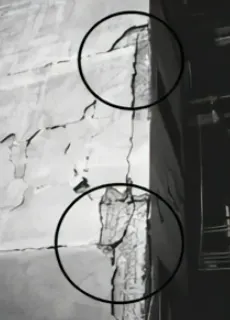
c) OBSERVATIONS:
- The cracks generated in the column-beam junction.
- It occurred in the entire width of the beam.
- Few cracks have developed in the slab along the direction of the beam.
CONCLUSIONS:
- The deformation in the beam means no capability to resist the moment and permit free rotation, so it is a plastic hinge failure
- The plastic hinge failure happened at the joint only, so the damage occur in the junction.
- The main reason for the damage is cyclic lateral loading and stress reversal at the junction.
- It can be repaired by strengthening the column-beam junction.
AIM 2 : What is the mode of failure or damage of the beams in the figure BELOW? Are the damages repairable? Elaborate
a) b) c)
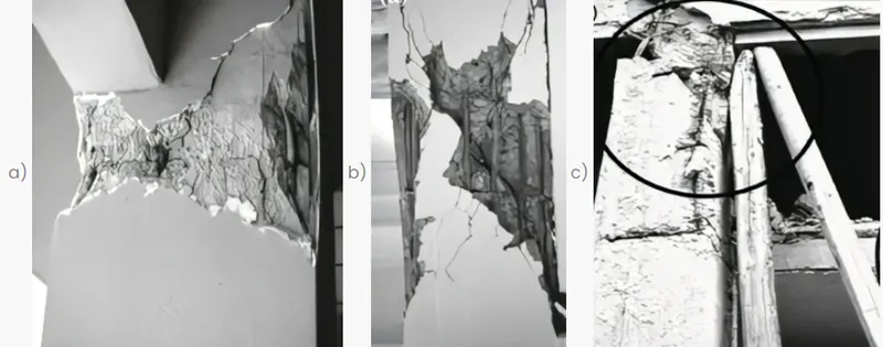
a) OBSERVATIONS:
- The column has been damaged from the top but the bottom of the column is safe.
- The damage is all around the face of the column.
- No damage is visible in the beam.
- It may be the outer or external column of the building.
CONCLUSIONS:
- It is technically plastic hinge formation at the column.
- Due to the lateral movement in the building and the absence of walls, columns got affected because of the plastic hinge formed at the upper side of the ground floor.
- The fall out of the concrete from the column and the severity of the column is to be decided as either repairable or non-repairable only by physical examination. If the rebars are damaged severly due to weathering so it would be non-repairable
b) OBSERVATIONS:
- Lateral and longitudinal reinforcements are visible. Rebar has been damaged and not separated.
- The breakage of concrete has diagonally developed in the column, it is completely crushed and concrete detached from the column.
- The clear vision of lateral reinforcement, shear links spacing is seems to be more than as per codel requirements.
CONCLUSIONS:
- This is a pure shear failure because the crack is in a diagonal direction and the complete concrete had damaged.
- The shear reinforcements were not sufficient, they had detached and spoiled throughout the column. It had compelled concrete to break down into the pieces.
c) OBSERVATIONS:
- The column is completely failed. Damage happens at top of the column
- As per the picture, there are two slabs connected with the column and the space between both slabs is not the floor height.
- The beam has been temporarily supported with the wooden piles after the column failure to avoid the collapse of the structure.
CONCLUSIONS:
- The failure is short column failure.
- The column is attached to an intermediate slab and the height of column is not similar to the other columns, so there is a heavy shear load on the column.
- The intermediate slab load is unintentional and may not be accounted for the design. Hence the failure is not repairable.