Identification of Cracks
1. a)
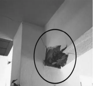
This figure shows a Damage at the Beam-Column Joint. It is clearly observed that there is more damage in the part of beam. It is caused due to not providing sufficient cover to the beam from the reinforcement or due to insufficient vibration of concrete as there will be hinderence of the reinforcement while vibration. The repair can be done by providing proper cover at the joint.
b)
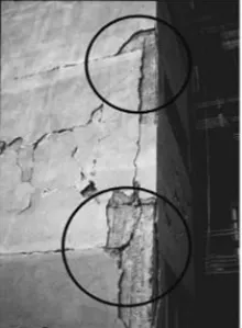
This figure shows a Damage is caused due to improper shotcrete plaster material. This damage can be repaired by removing pieces of plaster surrounding the damaged material and shotcreting once again by applying suitable adhesive
c)
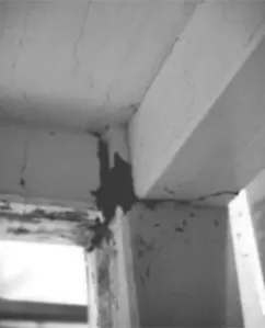
This figure shows a Damage at the Beam-Column Joint failure. It occurs due to joints subjected to high shear forces. This damage can be temporarily repaired, but during the long run this damage may cause Harm and also can turn into a failure
2. a)
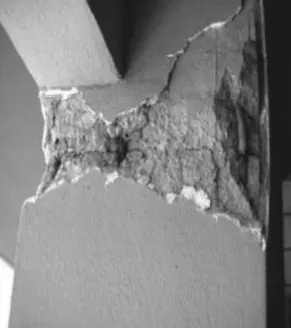
This figure shows a Failure of column due to buckling. The column should be long column, even though the beams are provided at intermediate levels the column couldn't resist the buckling load so the failure occured. Generally buckling occurs at the midpoint of the column where BM is maximum and shear force is zero. To avoid this type of failures reinforcement should be provided in such a way that lapping of all reinforcement bars in a single column not meeting at the same point. It is better if alternate bars are provided for lapping of joints
b)
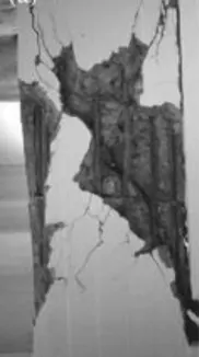
This figure shows a failure due to Shear. Generally shorter columns attractt high shear forces. This undesirable mode of deformation caused called as SHORT COLUMN EFFECT. It is mainly observed failure during Earthquakes which generally occur at the open ground floor levels
c)
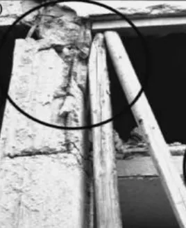
This figure shows a failure at Beam Column Joint. It is looking like the column got misplaced after concreting and during which the concrete was unable to set for the required dimension. So it resulted in uneven placement of concrete which caused the exposure of environment.