Hood design-Week 2
Aim: To Design Hood outer panel, inner panel and the necessary reinforcements by following the Master section with the design parameter
Introduction: Hood is the main component of a car at the front portion. It is used to decorate the car and add a luxurious look. The shape of the Hood is made aerodynamic in order to minimize the air effect. Hood is generally used to access the parts easily such as radiator, engine and many other parts. A car hood, also referred to as a bonnet in some other countries, is the hinged cover that rests over the engine of a front-engine vehicle. Its purpose is to provide access to the engine for repair and maintenance. A concealed latch is typically used to hold down the hood. On vehicles with an aftermarket hood and on race cars, hood pins may be used to hold down the car hood. Hoods sometimes also contain a hood scoop, wiper jets, power bulge, and/or hood ornament. Car hoods are typically constructed from steel and sometimes from aluminum. Aftermarket car hoods may be constructed from various other materials, including carbon fiber, fiberglass, or dry carbon. The hood design may vary from one make and model to another.
while access for repairs and maintenance Hood can fix by two methods
1. Support Rod
2. Gas Stay
In the fig 1.1 shown Support Rod and Gas Stay
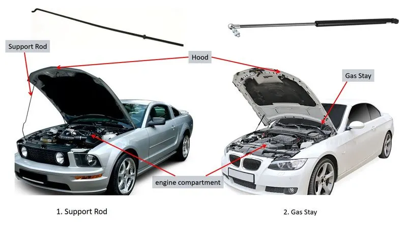
Fig.1.1: Support Rod and Gas Stay
In the fig 1.2 shown Hood and its parts
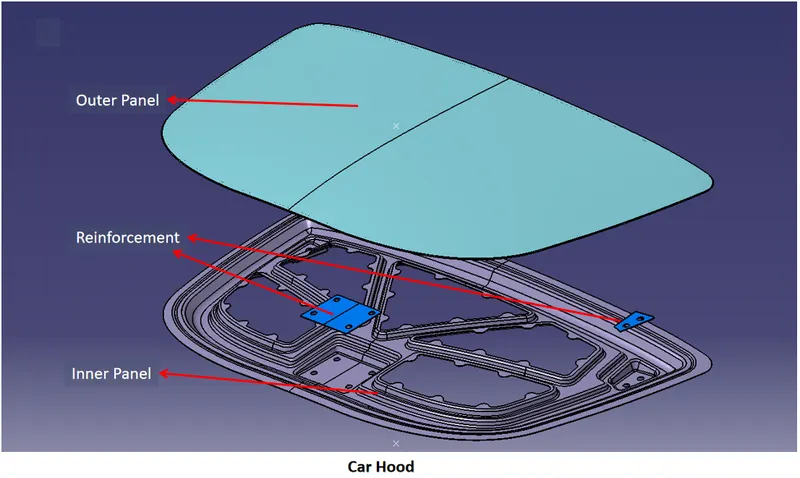
Fig.1.2: Outer Panel, Inner Panel & Reinforcement
Design requirements for Car Hood
1. Hood Head zone for lock striker: In the fig 2.1 shows Hood Head zone for lock striker
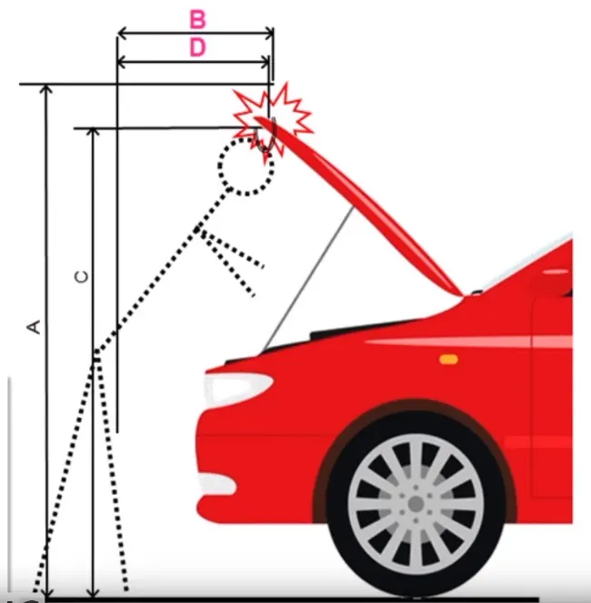
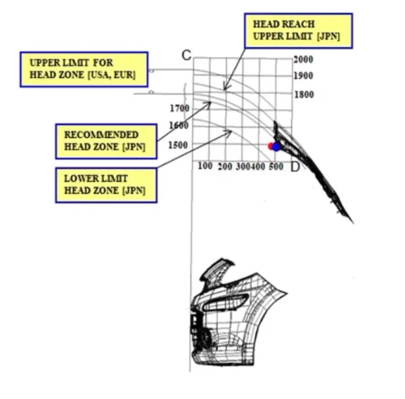
Fig.2.1: Hood Head zone for lock striker
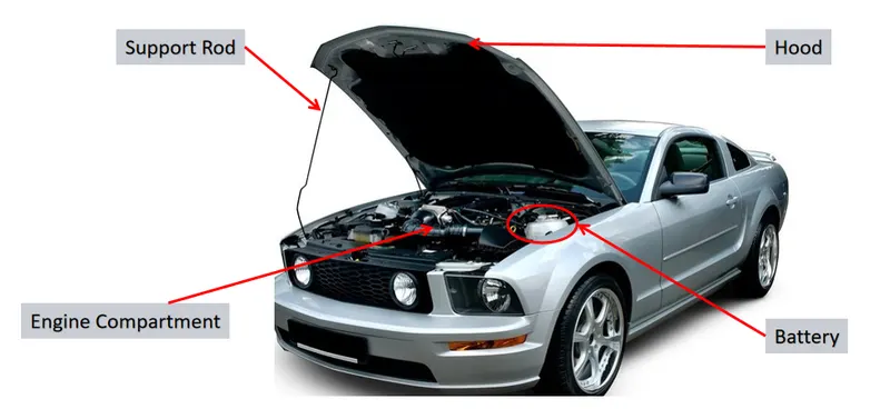
From the Fig. The opening angle of hood will give A, C, B And D with respect to the ground. those A, B, C & D are decided in the head zone. Opening angle varies from region to region depending on average human weight. Depending on the standards we are deciding the angle. So from the angle data, Support rod or Gas stay is designed. The position of Support rod is on the other side of the battery which is shown in the fig. below.
2. Adding latches and stiffener pad: Latches are added where and all the weight is added. On the inner panel we have Hinges and striker, which are attached to the inner panel so due to this attachment the strength of the inner panel is going weak. In order to strengthen the inner panel Latches will play a very important role. Stiffener pad is the sponge-like material place b/w Inner and outer panel to reduce vibrations.
3. Mastic Seals: Mastic Seals place b/w Inner and outer panel to reduce Noise, vibration, and harshness. Every Mastic will have an effect of 80mm Dia locally. shown in the fig 3.1. Inner and outer panel gap is 2 to 5mm
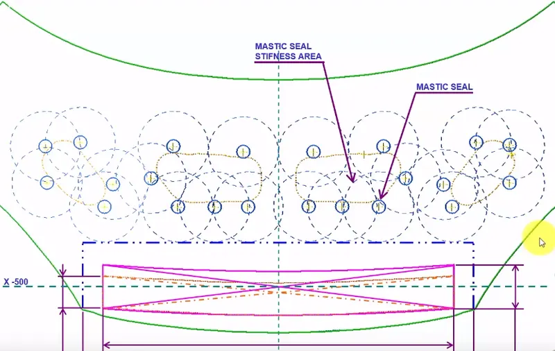
Fig.3.1: Mastic Seals
4. Emboss definition: Emboss are provided in the inner panel of the hood assembly. This helps in weight reduction of the hood and also to dissipate the force during collision. Force dissipate is shown in the fig. 4.1 this project design.
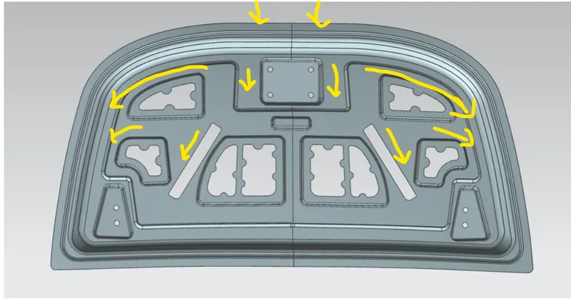
Fig.3.1: Force dissipate
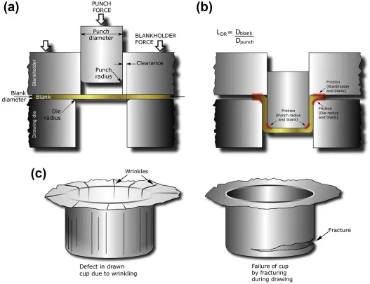
a. Deep Drawing: Deep drawing is a sheet metal forming process in which a sheet metal blank is radially drawn into a forming die by the mechanical action of a punch. It is thus a shape transformation process with material retention. The process is considered "deep" drawing when the depth of the drawn part exceeds its diameter.
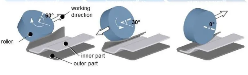
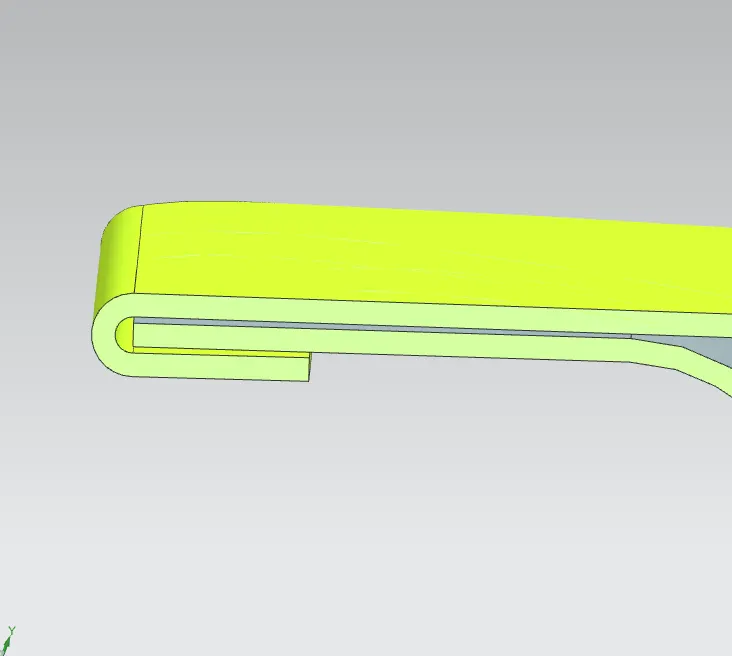
b. Hemming: Hemming is a forming operation in which the edges of the sheet are folded or folded over another part in order to achieve a tight fit. Normally hemming operations are used to connect parts together, to improve the appearance of a part and to reinforce part edges.
5. Hood For Better Pedistain Rating:
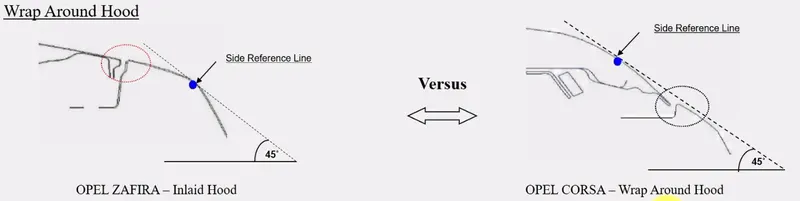
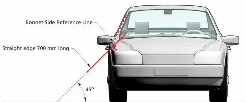
Inlaid Hood:The line which is drawn 45 deg. from ground to Side Reference of carand which is meeting point on fender is called Inlaid Hood.
Wrap Around Hood: The line which is drawn 45 deg. from ground to front surface of the Hood and which is the meeting point on the outer panel is called Inlaid Hood.
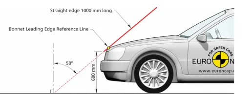
Depending on the Inlaid Hood & Wrap Around Hood we can design hood for head impact in the fig 5.1 shown position of head impactor.
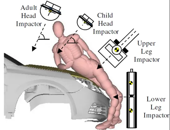
Fig.5.1: Position of head Impactor
So based on the position of head impactor we are providing emboss and cuts shown in the fig. 5.2
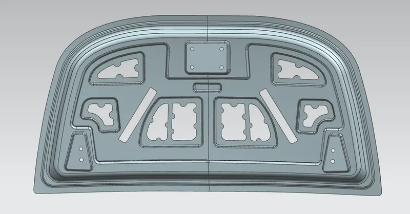
Fig.5.2: Emboss and Cuts
Design Methodology
1. Develop the inner panel with
- Embossing (with minimum 7 Degrees Draft)
- Mastic Points
2. Develop the Outer Panel with
- Hemming
3. Positioning the reinforcements
- Hinges
- Striker for Latch
Given data for Hood Creation
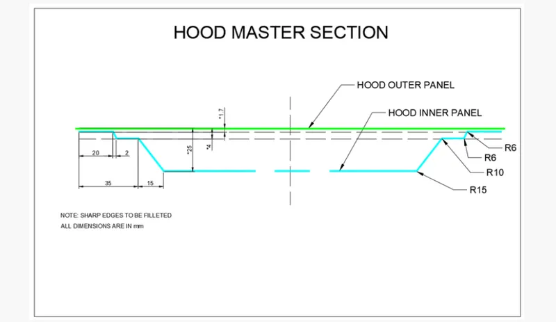
MasterSection
It has played very important role as it has every general design information considered for a hood. It shows general dimensions and structural shape of general hood design.
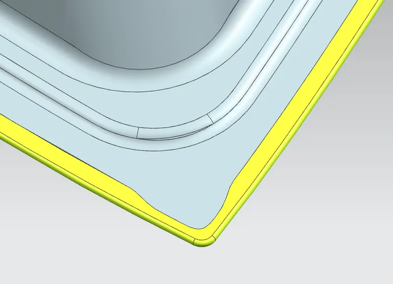
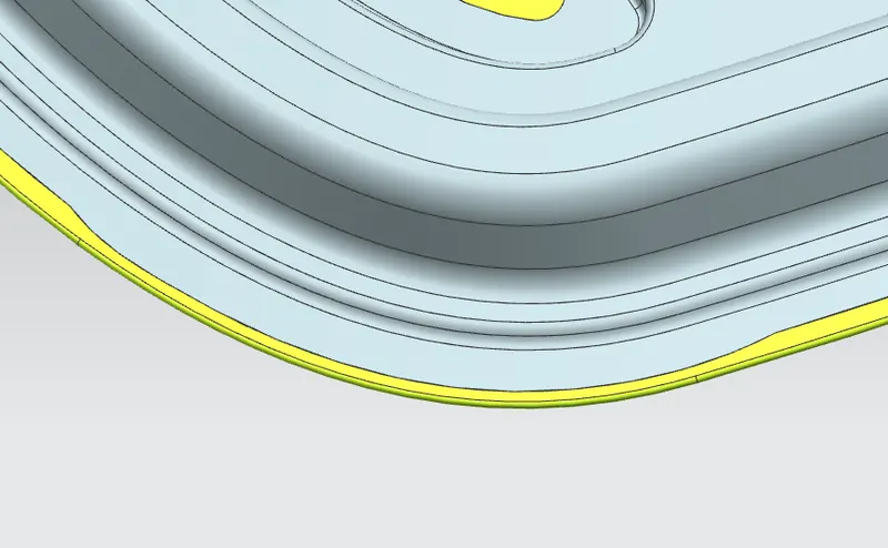
Hemming Data:
Relief rear section:
Front relief:
Data To be used
- Outer Panel Thickness 0.75mm
- Inner Panel Thickness 0.75mm
REMOVAL OF MATERIAL
For less impact on head in collisions(Pedestrain Safety), reduce tool cost, reduce material cost, ease of manufacturing and to make light weight.
POSITION OF STRIKER AND HINGE
For the proper opening and closing of the hood, the striker should be perpendicular to the trajectory of the hood. For this, hinge is assembled at its position. Once it is placed, hinge axis is drawn.
- To check the hinge axis as the center we draw a big circle to the position the latch in such a way that it is perpendicular to the hood trajectory.
- In between the two hinges, the striker is perpendicular to the midpoint of two hinges, because while closing and opening of latch and striker the opening position be similar actions.
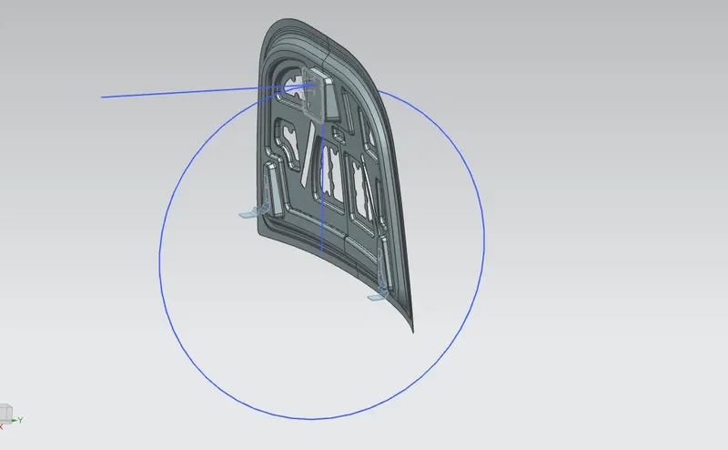
LATCH TRAJECTORY
The latch trajectory shows the path of the striker when the hood is opened and closed on a vehicle.
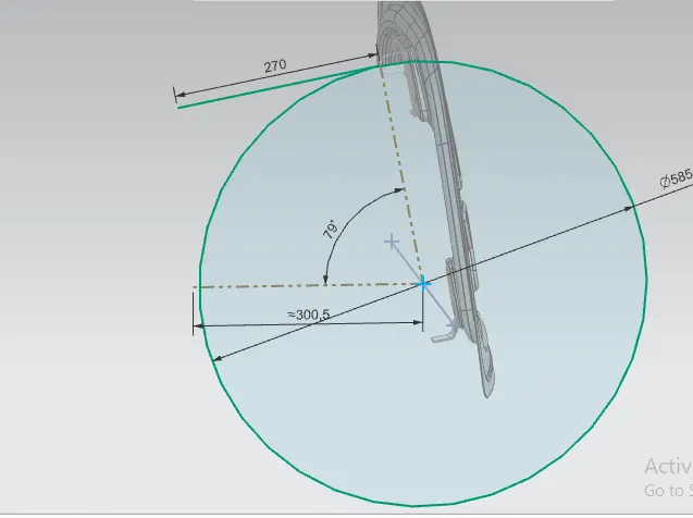
The radius of the circular trajectory is determined by the set standard based on the average height of a person. The radius is measured from the hinge axis up-to the latch.
STRIKER ANGLE OF HOOD
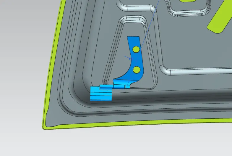
HINGE ASSEMBLY
Hinges is the assembly of components connected to the door and body of the vehicle, linked to each other and capable of rotating around the same axis. Conventional system consists of two hinges for each door, an upper hinge and a lower hinge.
STRIKER ASSEMBLY
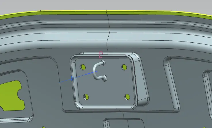
The door striker plates are installed in the door jambs, and precisely aligned with the door latches so that the latches catch onto the striker plate when the doors are closed. The door striker plate is made of hardened steel to resist wear as it is subjected to constant contact with the door latch.
The hood latch system begins inside the compartment of the car, hood release handle located onthe driver's side. The hood release handle attaches to a cable which then routes through the dashboard towards the front of the vehicle.
CORNER RELIEF
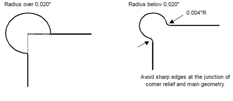
- Relief is provided onto the part or component in order to remove any stresses developed in a particular area i.e sharp corners that takes place during the hemming process is carried out. Thus corners are rounded or chamfered.
- Relief of 3 mm from sheet metal for Roll hemming process.
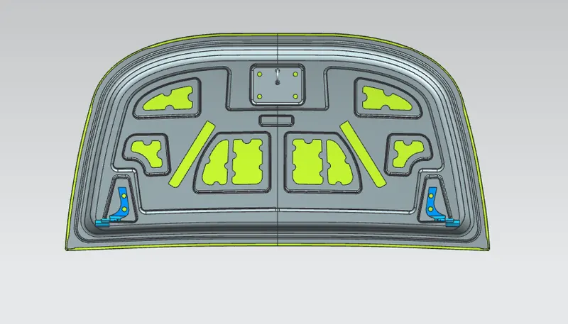
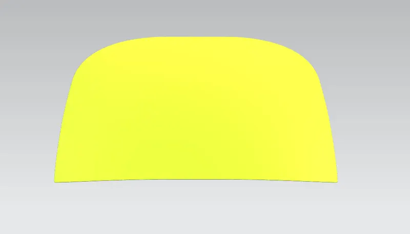
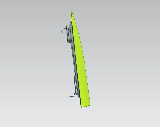
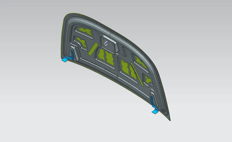
DIFFERENT VIEWS OF HOOD
FRONT VIEW
TOP VIEW
SIDE VIEW
ISOMETRIC VIEW
CONCLUSION
This hood was designed in Siemens NX CAD software with given and required design guidelines for hood design and manufacturing.