Hood design-Week 2
DESIGN & ASSEMBLY OF A HOOD IN CATIA V5
OBJECTIVE:
- To design and develop a Hood Assembly (Hood Inner Panel, Hood Outer Panel, Reinforcements for Striker and Hinges) from the given skin data, master section and design parameters
- To explain the terminology involved in the design process of a Hood
- To explain the manufacturing processes employed in the creation of a Hood
INTRODUCTION:
Hood: is one of the most important and versatile components of an automobile. Also known as Bonnet, its main purpose was to act as a hinged cover and allow access to the engine compartment of a motor vehicle for repair and maintenance. It protects the components in the engine compartment from the atmospheric aspects and other damage. Over the years, it became a major styling component in highlighting the aesthetics of the vehicle and more recently it is being used as an active structure in the improving the safety standards of a vehicle. It is to be noted that, the Hood, along with the frontal portion of the car, is to absorb maximum impact upon collision and redirect the forces towards its hinges and the into the body frame to minimize the damage to the driver and the passengers. Pedestrian safety is also taken into consideration and regulations have come into effect to keep in check the severity of head injury to the pedestrians when struck by a vehicle.
A Hood is safely held up either by a Support Rod or a Gas Spring when fully extended. They are often mounted to the inner left, when viewing head-on, to avoiding unnecessary obstruction to the technician while performing the inspection and maintenance of the engine compartment. Depending on the design and weight of the hood, a secondary support is also provided in the opposite end
Support Rods are made of carbon steel to avoid bending or buckling under the weight of the hood. They are given a slightly curved shape to fit properly in the engine compartment and also to lock onto the latch which is provided either on the hood or in the engine compartment. Due to simple design and light weight, they are seen in majority of vehicles.
Gas Springs, commonly known as Gas Struts or Gas Stays, are a type of springs that use a compressed gas cylinder with a sliding piston to pneumatically store potential energy and withstand external force applied parallel to the direction of the piston shaft. These are often provided in premium cars for easy and smooth opening and closing of the hood without much effort.
DESIGN:
The Hood Design can be approached as depicted in the flowchart below
- Study the given information and prepare the given skin data
- Develop the shape of Inner Panel from the given skin data and provided Master Section
- Design the necessary embosses, cut-outs and mastic points for the Inner Panel
- Develop the Hemming for Outer Panel providing Corner Relief as indicated
- Develop the Reinforcements for Hinges and Striker
Given Information:
The given data and design parameters are as follows:
- Hood Thickness information
- Outer Panel Thickness = 0.75mm
- Inner Panel Thickness = 0.75mm
- Reinforcement Thickness = 1.5mm
- Master Section:
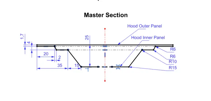
- Hood Inner Panel:
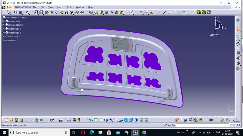
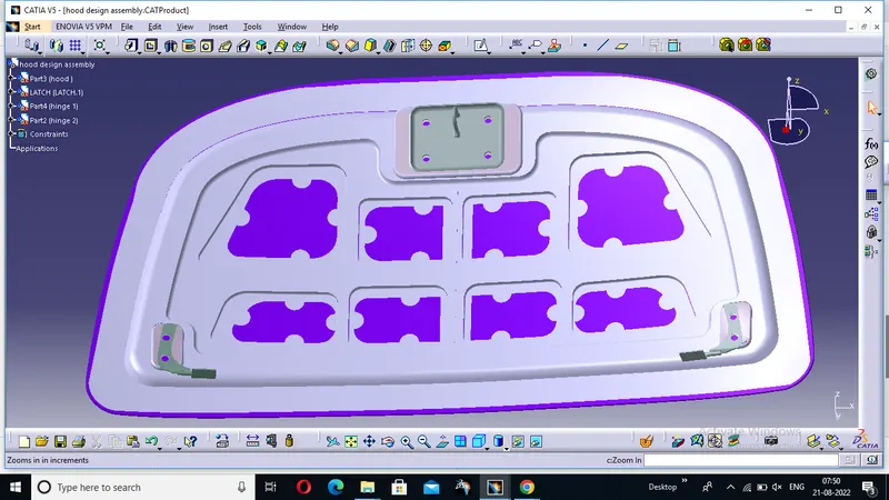
The structural integrity of the hood depends majorly on the inner panel. It is only on the inner panel, that the structural elements can be designed and the reinforcements can be attached to. Here, the basic shape of the Inner Panel is created from the provided thickness information and the Master Section. Apart from the given information, it is crucial that the inner panel is provided with embosses in a way that the impact forces are directed towards the hinges. Cut-outs are also provided to reduce the component weight 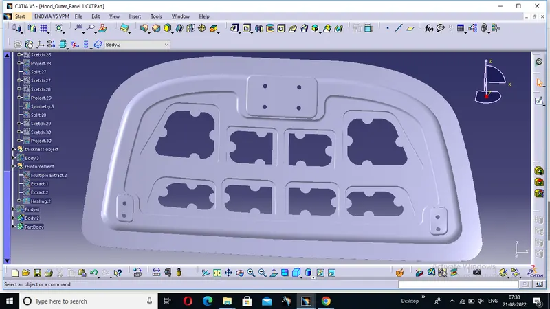 IN THIS IMAGE WE CONSIDERED 0.75 MM THICKNESS
 - Reinforcements:
Both Hinges and the Striker are fastened to the inner panel by means of screws and bolts. Reinforcements of thickness as provided in the given data are spot welded to the mounting regions on the Inner panel to provide additional strength.
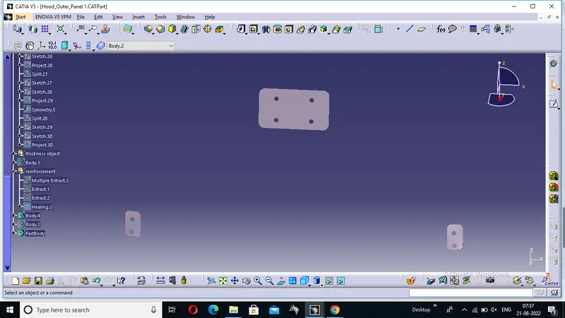
HERE WE CONSIDERED 1.5 MM THICKNESS
Hood Outer Panel:
The Outer Panel of the hood is already well defined by the input skin data and is often developed without altering its outward design. The only addition is the extension for Hemming which fixes the Outer Panel in place with the Inner Panel. Here, the provided Hemming data and the Corner Relief parameters are taken into consideration in developing the Outer Panel.
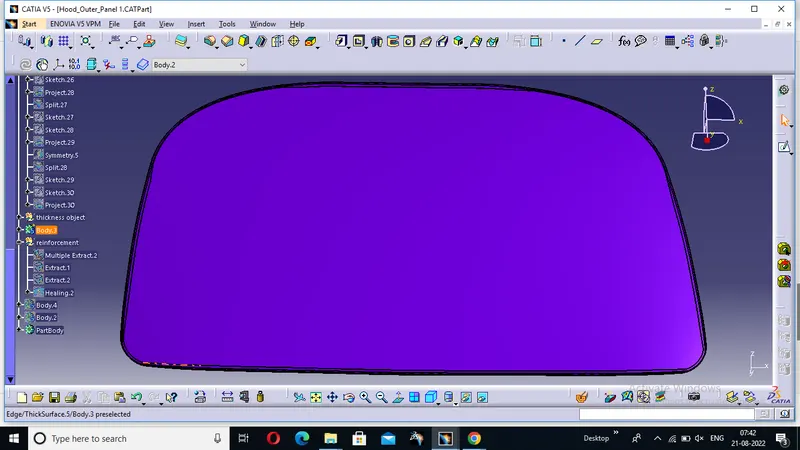
HERE THE CORNER RELIEFS ARE 3MM AND HEMMING SURFACE IS CONSIDERD AS 6 MM
Hood Assembly:
The Inner Panel, Outer Panel, Hinges and the Striker are assembled in the Assembly
Mastic Points:
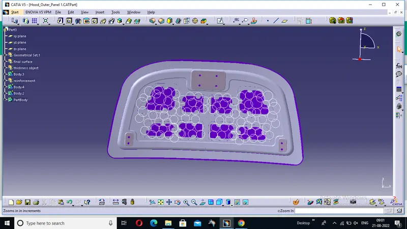
The Hemming process fixes the Outer Panel and Inner Panel along their outer edges, but the inner portions of the two are loose and susceptible to vibrations. This may lead to wear and even deformation of either component. This is dealt by applying a Mastic Adhesive at points wherever necessary to curb the vibrations and glue both the panels firmly. Here, 135 Mastic points have been provided to ensure sufficient contact between the two panels.
Latch Trajectory and Hinge Axis:
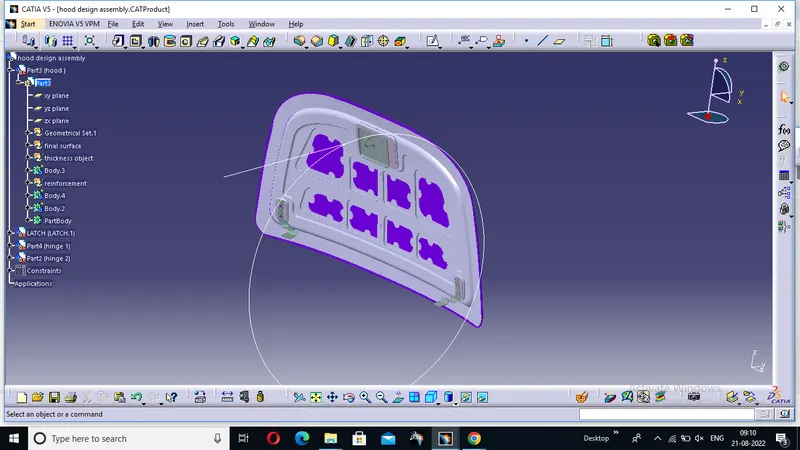
The Hood is mounted on to the Car body with the support of two hinges, one on either corner. To lock the Hood closed, a Latch and Striker mechanism is used. The striker is mounted on the Inner Panel of the Hood, while the Latch is provided on the car body. Here, the embosses for the Hinges and the Striker are created by first aligning the Hinges with the Inner Panel and then creating a Hinge Axis around which the trajectory of the Latch and Striker mechanism is created. The Striker is then aligned to the trajectory and the Inner Panel as well. After finalizing the positions of the Hinges and the Striker, the necessary embosses are created and then added to complete the Inner Panel.
Manufacturing Processes employed in creating the Hood:
1) Deep Drawing: is a sheet metal forming process wherein a sheet metal blank is converted into a cup-shape by pressing the sheet metal in the centre with a circular punch fitting into a cup shaped die. During the process, the sheet metal is subjected to a complicated pattern of stress making it one of the most difficult sheet metal operations. The portion of the sheet between the punch and the die wall is subjected to pure tension, whereas the portion at the bottom is subjected to both tension and bending. The outer end portion of the sheet between the die blocks is subjected to circumferential compressive stress and buckling. Here, the basic shape of the Hood Inner Panel is achieved from deep drawing.
2) Embossing: is a sheet metal forming process in which impressions are made on a sheet metal blank such that the thickness remains uniform throughout the sheet even after embossing has been done. It is a form of pressing operation where not much force is needed. The blank is kept on the bottom half of the die and the stroke of the punch is adjusted that, when it moves down to its lowest position, it leaves a uniform clearance between the impressions carved in the punch and the die which is equal to the thickness of the sheet being embossed. As a result, the design is transferred on to the sheet by bending the sheet up or down without altering its thickness. Here, embosses are provided on the Inner Panel to both increase the structural rigidity as well as to transfer the impact forces towards the hinges.
3) Blanking: is a form of sheet metal punching process in which a sheet metal is kept on a die and is sheared or pierced by a punch of desired profile. Here, the punched-out part is called a blank and usually requires no further machining. This process is ambiguous with punching. Here, the outer shapes of both the Inner and Outer Panels as well as the corner relief for hemming of the Outer Panel are obtained by this process.
4) Punching: is a form of sheet metal punching process in which a punch is forced through a sheet metal to create a hole of desired profile. Here, the part of the blank which is punched is the workpiece and the punched-out part is scrap. Here, this process is used for removing material in the form of cut-outs and holes wherever required on the Inner Panel of the Hood.
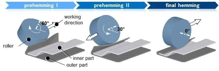
5) Hemming: is a sheet metal forming process in which the outer flanges of a sheet metal are bent and rolled over onto the sheet metal itself. This is commonly used to reinforce the edges, hide the burrs and rough edges thereby improving the appearance of the sheet metal and offering safer handling of the component. Here, the extended flanged edges of the Outer Pamel are bent over to wrap around the Inner panel so that both the parts are fixed together. As the shape of the bending region is a closed profile, it is suggested to provide corner reliefs wherever necessary to avoid inaccurate overlapping or wrinkled edges. Usually, in automotive applications, Roller Hemming is employed for effective and efficient manufacturing.
IF YOU ARE UNABLE TO FIND THE ASSEMBLY KINDLY CONTACT ME,