Hood design-Week 2
Designing the front hood:
1. The front portion of the car which covers the engine compartment is known as the front hood.
2. It consists of two major components: the inner panel and the outer panel. The hood is the most critical BIW component as it concerns pedestrians and passenger safety.
3. The Euro NCAP safety standards are used to design the outer panel and inner panel.
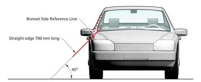
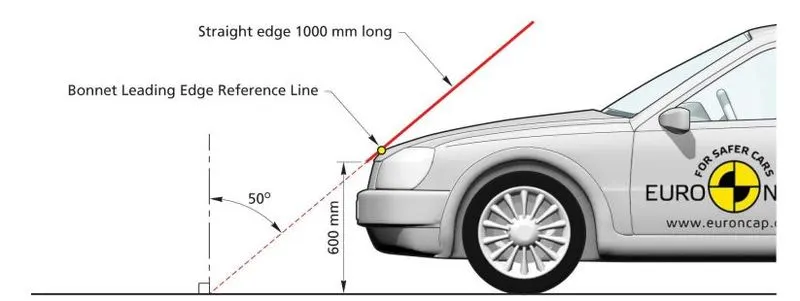
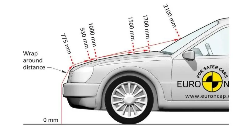
4. The standards of the EURO NCAP for the hood are shown below:
side-impact:
front impact:
Wrap around distance:
Impact zone for adults:
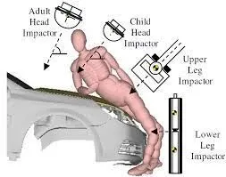
Impact zone for Child:
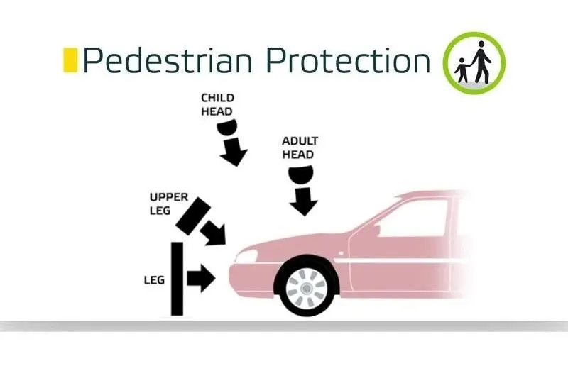
Different Impact zones on the hood:
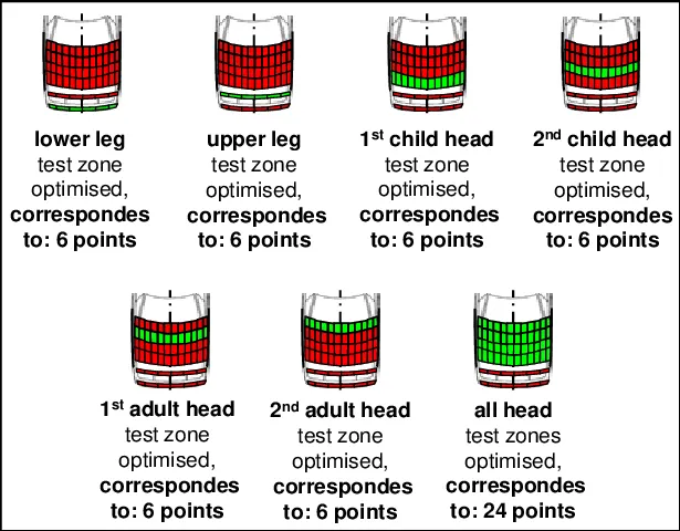
The zone which contains more green colour resembles that it has more safety to the pedestrian impact.
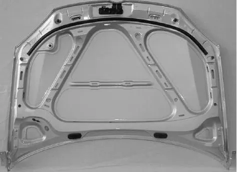
To reduce the impact of the crash which protrudes towards the A-pillar of the car, The inner panel plays a major role.
The embosses which are present on the inner panel are designed in such a way like V or Y-shape so that the impact drives away from the A-pillar reducing the impact coming towards the passengers in the car.
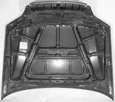
Some examples of the inner panel are shown below:
Designing the hood using the given master section and the outer panel:
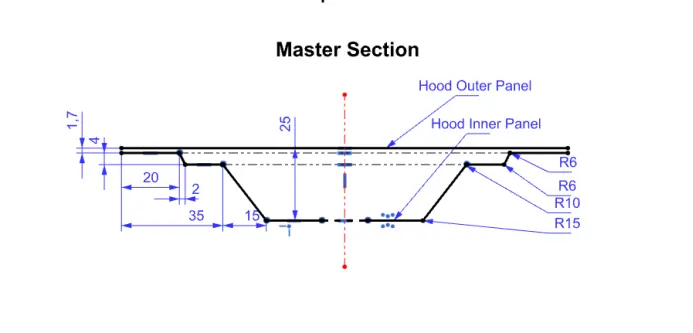
given master section
1. Using the outer panel, offset the outer panel and make it as a working part.
2. The working panel is offset to 1.7mm, 4mm and 25mm as shown in the master section.
3. The panel which is offset to 25mm is considered as the base of the inner panel. And from the base, we emboss 10mm towards the outer panel.
4. Emboss is a design in which we raise to a certain amount of height from any selected surface. for example, Using the base of our inner panel, We draw a sketch and then we project the sketch on the inner panel face. Using the emboss command we select the sketch that we drew on the inner panel. We provide offset distances such as 5mm or 10mm as per our design constraints.
5. After creating the emboss, mastic points and cutouts, we use the mirror geometry command. Using this command we mirror all the sketches and features to create the other half of the inner panel.
6. Once the mirroring is finished we use sew command to join the two halves of the inner panel.
7. The sewed inner panel is now thickened to a thickness of 0.75mm.
Image of embossing:
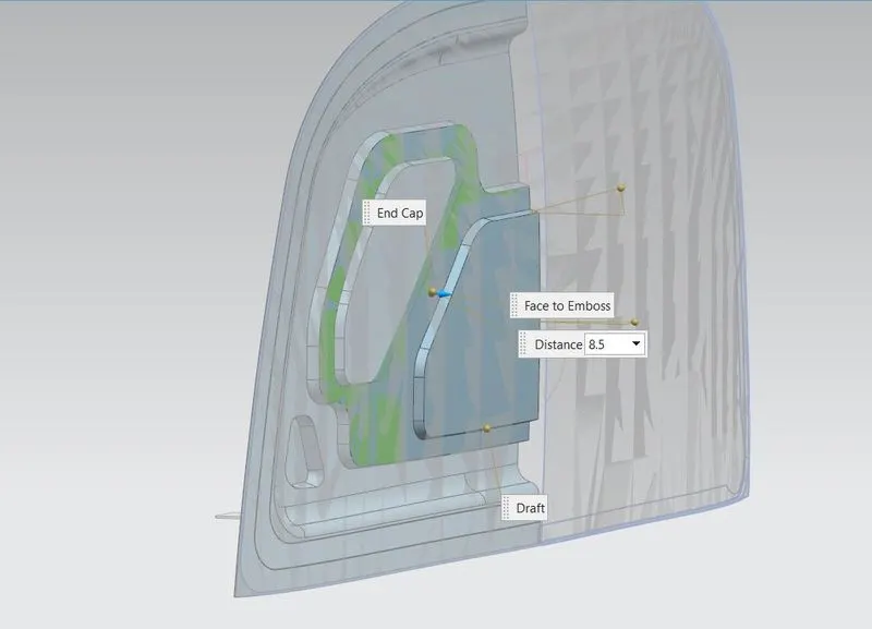
5. For manufacturing the emboss, a deep-drawing process is used. Deep drawing is a sheet metal forming process in which a sheet metal blank is radially drawn into a forming die by the mechanical action of a punch. It is thus a shape transformation process with material retention. The process is considered "deep" drawing when the depth of the drawn part exceeds its
diameter. This is achieved by redrawing the part through a series of dies.
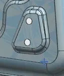
emboss of inner pannel and for hinge:
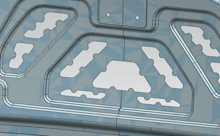
6. Now after we create the inner panel we join the outer panel from the top. To perform this operation we provide mastic points. On these mastic points, we attach mastic glue which joins both the panels.
7. The mastics improve the NVH levels by decreasing the vibrations and noise which come from the engine hood.
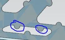
8. As shown in the image, the semicircle pattern act as mastic points to join both the panels.
9. The cutouts which are present on the inner panel reduce the weight of the inner panel and also reduce the impact on the pedestrians.
10. If there is more material in the pedestrian impact zone, then the impact received by the pedestrian is higher during an impact.
Hemming:
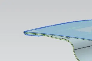
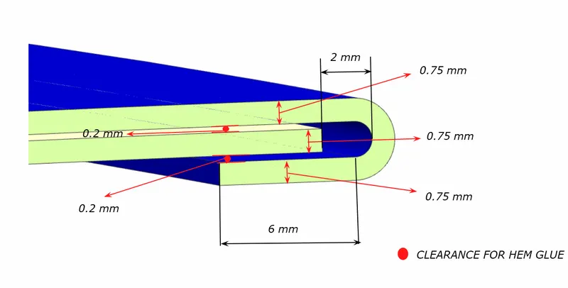
Hemming is the process where the outer panel sits on the inner panel and the outer edge of the outer panel wraps inwards on the inner panel.
Using the outer panel as the working part, we offset it at 0mm and use the law extension command to extend the edge of the sheet.
This extension is used to wrap the outer panel around the inner panel. This hemming holds the inner panel to the outer panel.
Striker positioning using hinge assembly:
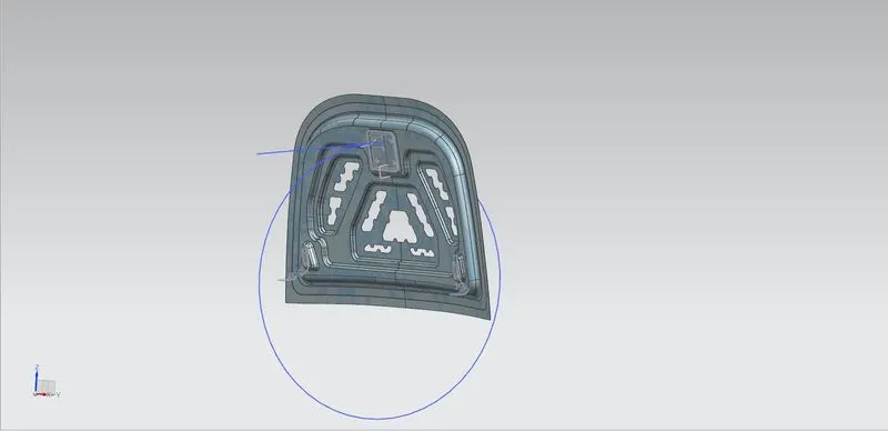
To position the striker at the top centre of the hood and the hood manufacturable we perform certain steps. The steps are as follows:
1. Place the hinges at the hinge points on the inner panel.
2. Select the curve of the hinge assembly and mark the point at the centre of the curve.
3. Now using the point draw a line joining both the hinges on either side of the inner panel.
4. Now draw a circle with a random diameter, and join the centre of the circle to the centre of the curve of the hinge.
5. After joining the circle, Draw two lines horizontally and vertically from the centre of the circle to the circumference. Make the two lines for construction.
6. Now draw another line tangent to the circle. This tangent joins with the line that is drawn by the striker.
7. Insert the striker into the assembly. Assing a plane to the striker. Draw a line similar to the tangent drawn to the circle.
8. Using the assembly constraints command, select the point of the line drawn from the striker and the line tangent to the circle.
9. These two points act as the position of the striker. If we change the angle between the lines drawn from the centre of the circle, the angle of the striker changes.
10. If the diameter of the circle changes then the position of the striker changes. In this way, we position the striker.
Draft analysis:
Draft analysis is required to make the manufacturing process feasible. As the hood's outer and inner panels are sheet metal components and the thickness of the panel is very low. These components are manufactured using a deep drawing process. In this deep drawing process, the tool moves into the panel and creates the emboss. After drawing into the panel, the tool has to come out of the panel. To draw the tool outwards the emboss should have an angle of a minimum of 7 degrees.
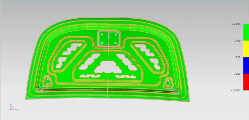
If the sheet metal component has more blue and red areas it shows that the draft angle has to be increased to make the manufacturing possible.
Reinforcements for striker and hinges:
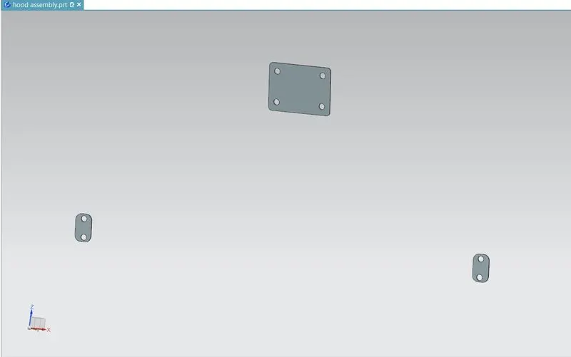
1. As we know the hinges and the striker adds some weight to the hood at the hinge points and the striker point.
2. Due to this weight the stress on the inner panel increases. To increase the strength at the hinge and striker placement we add reinforcement with a thickness of 1.5mm.
Images of the assembly:
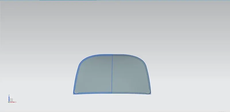
Outer panel:
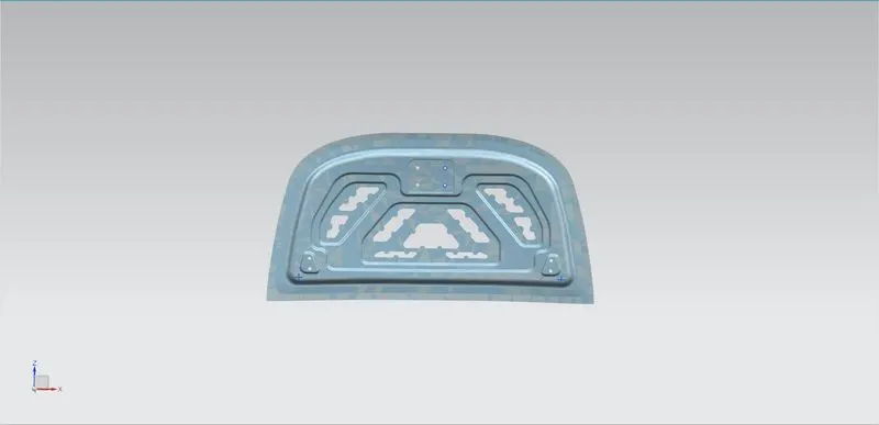
inner panel:
assembly isometric view:
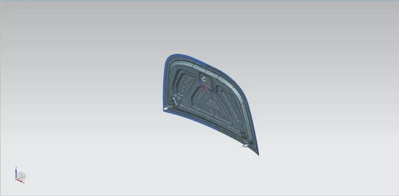
assembly front view:
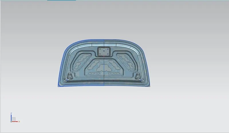
hinge and striker assembly:
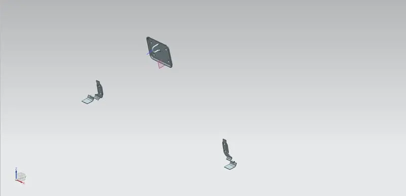
section view inner panel:
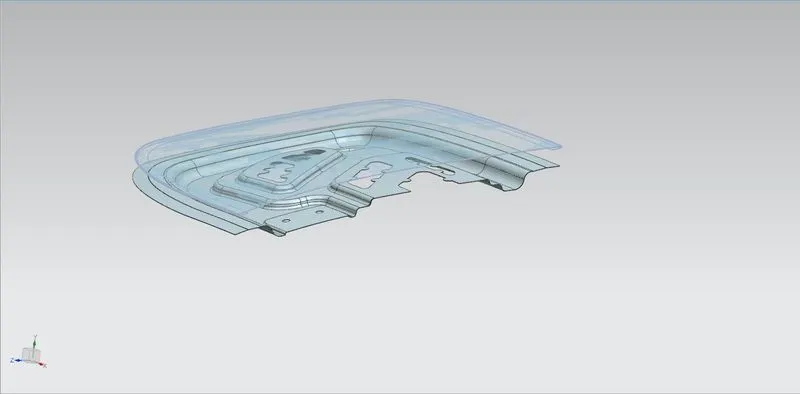
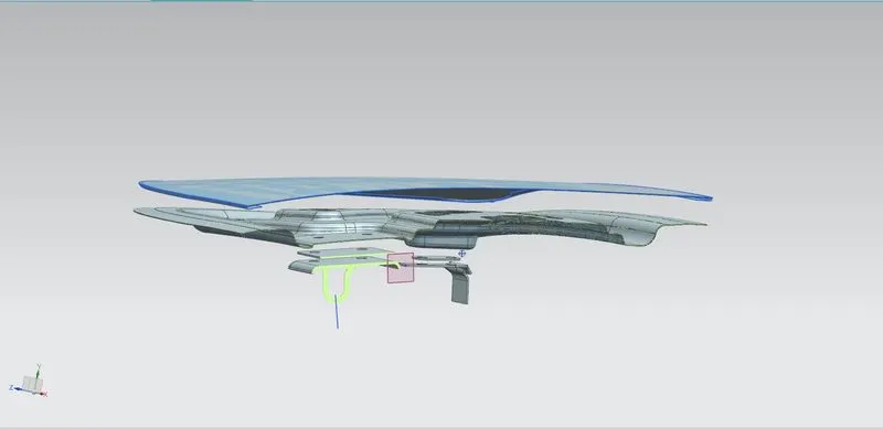
exploded view assembly:
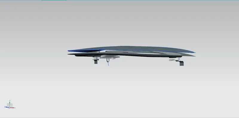
Exploded section view:
conclusion: As per the given master section, the inner panel is created by providing embosses and positions for hinges and striker. Hemming is done to attach the inner panel to the outer panel. Reinforcements are added to the striker and hinges to increase the strength of the inner panel.