Hood design
Objective:
- The main objective of the project is to create the Assembly of Hood by using the Siemens NX Cad software.
- To design the Hood inner panel with the given master section data by using siemens NX cad software.
- To assemble the hood with the given individual components and with the designed hood inner panel by giving the appropriate constraints.
Introduction:
Design of any component depends on the requirements of consumer. A design engineer sketches the components based on the consumers requirement. Then the 2D sketch is designed and the proper dimensions should be given to the sketch. Now the 2D sketch is converted into the 3D model with proper dimensions with the help of advanced Cad software.
The important thing in the design is that every component that is designed to be easily manufactured. So, the role of design engineer is to design the component that meets the customer requirements and to be easily manufactured with effective cost. This is the place where the Design for Manufacturing and Design for assembly takes a role while developing any product.
Introduction of Hood:
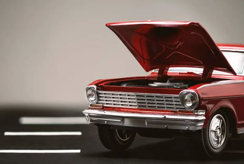
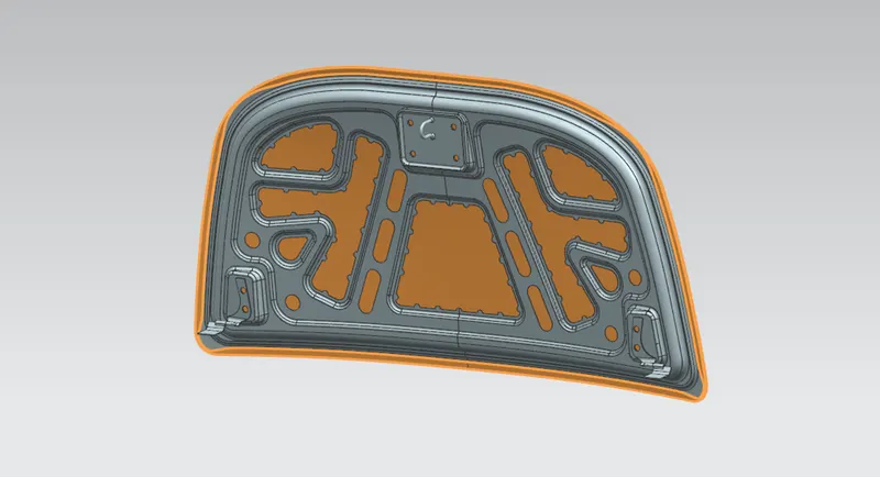
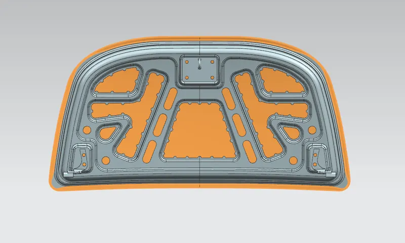
Hood of the car is a main component in the front zone which is used to cover the engine compartment. Hood consists of inner panel and outer panel which is joined together by hemming process at the edges and the middle area is joined by using the mastic data.
Hood is designed in such a way that can be opened and allowed to access the engine compartment for the maintenance and any other kind of purposes like battery replacement.
Hood inner panel provides the strength and protection for the engine compartment and while the outer panel acts as a metal cover also known as styling surface which gives a visual appearance to the consumer.
A car hood panel is one of the most important components of the BIW and which is considered as a closure sheet metal component.
Hood consists of:
- Hood inner panel.
- Hood outer panel.
- Latch and Stricker reinforcement.
- Hinge assembly reinforcement.
- Stiffener pad.
Structure of hood:
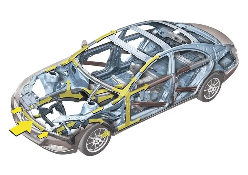
Hood is one of the most important components of BIW and also safe guard the passengers inside the cabin. The hood is designed in such a way, when a car undergoes a frontal crash, the maximum amount of force is dissipated towards outside and only less amounts of force goes to the passenger cabin of a car.
Due to this, the impact is less to the passengers inside the cabin which reduces the injuries to the passengers inside a cabin. And also, a hood is designed in a way, that also acts as an aerodynamics to the vehicle.
Design considerations of Hood:
The important points to be considered before designing the hood are:
- Hood head zone criteria.
- Pedestrian head impact zone criteria.
- Direction of force dissipation.
- Wrap around distance.
- NVH level.
- Euro NCAP crash tests.
Hood head zone criteria:
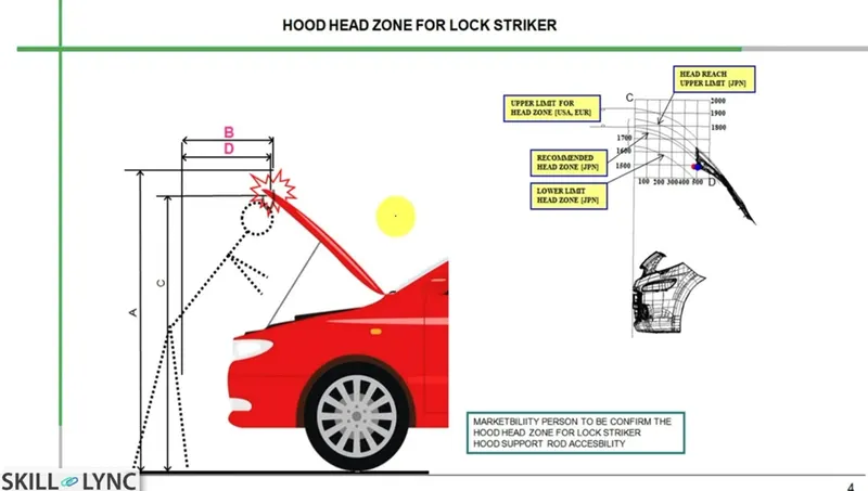
Hood opening angle is one of the most important parameters while designing the hood for head zone criteria. Opening angle of hood varies from person to person and also varies from country to country.
For example, an average height of Indians is 5.8 feet, where as an average height of Europeans is 6 feet. Based on the height of humans, the opening angle of hood varies from country to country accordingly.
The hood opening angle is considered to be very important because if the opening angle of hood is less, then there is a chance to occur a head injury to the human.
A car hood is kept in an open state with the help of a support rod. The support rod is placed accordingly to achieve the opening angle based on country’s human’s height.
There are two types of rods are available to hold the hood, they are:
- Support rod.
- Gas stay.
Support rod:
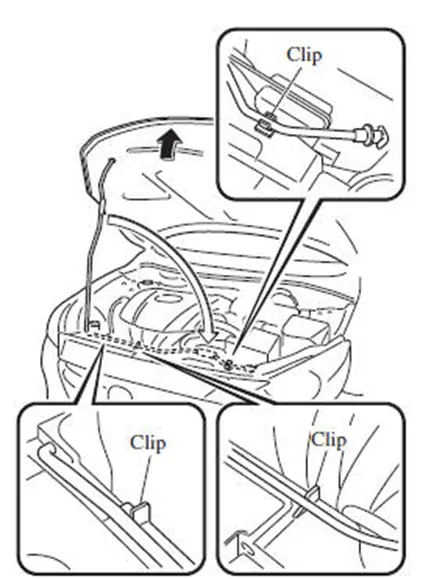
A hood support rod can be used to keep the hood in open state safely even if an any external forces are abruptly generated due to the vibrations or wind. It can be used for opening and closing of engine hood panel.
Design consideration of support rod:
- We need to design the support rod which should not be collided with any other component in the engine compartment. If the collision is happened between the support rod and with any other parts in engine compartments it leads to produce the noise when the car is in motion which causes NVH (Noise, Vibration and Harshness).
- The support rod to be designed with appropriate bends because the straight rod provides wobbliness which leads to produce NVH and the straight rod doesn’t have a that much amount of strength. So, the support rod with appropriate bends should be preferred for the rigidity and to avoid the wobbliness.
- Another important thing needs to consider while designing the support rod is that the support should be fixed or mounted on the opposite side of the battery placement. Because the rod should not produce any interface while mounting or replacing the battery.
Gas stay:
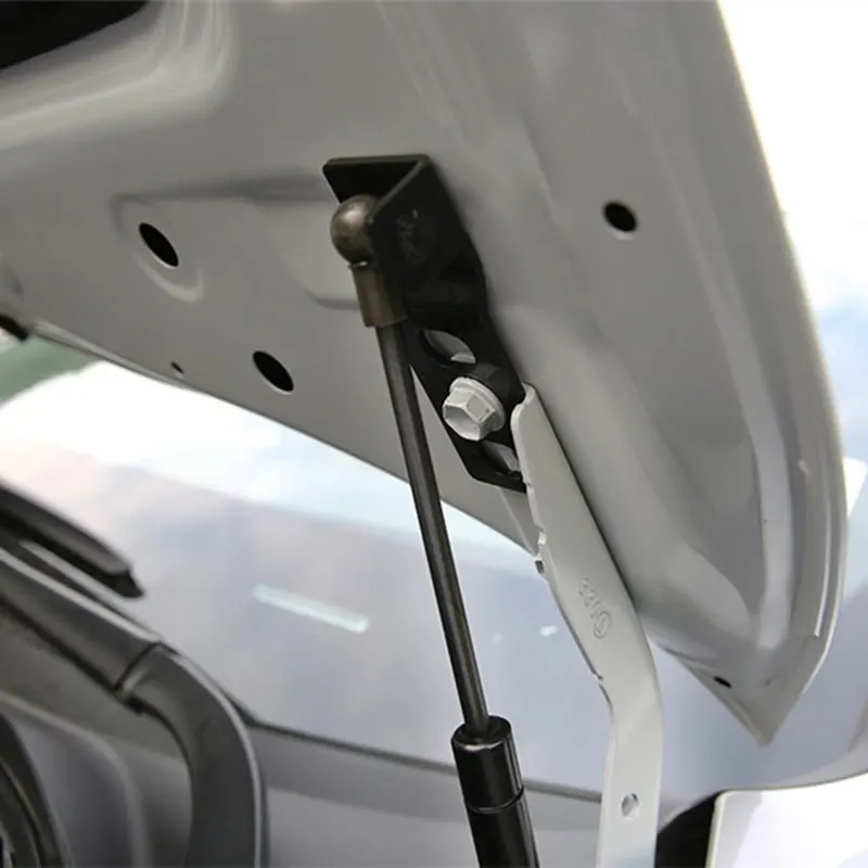
A gas stay (also referred as a gas spring) is a spring that operates due to the force exerted by the compressed gas usually known as nitrogen gas which is stored inside the cylinder.
Luxury carmakers provide a gas strut to lift the car hood and hold it in a place. It takes only a minimal human effort to lift it.
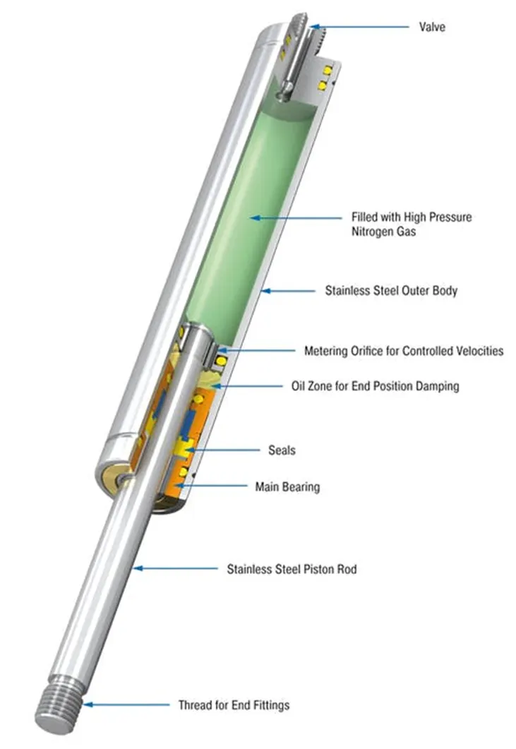
Design considerations of gas stay:
- The main important parameter for designing the gas stay is to determine the dimensions and weight of the object to be moved. The weight of the object to be moved is calculated with the help of spring scale.
- The body of gas stay must be fitted within the assembly without limiting its range of motion.
- The pivot point of hinge provide the support and it is the axis of rotation for hood openings.
- To determine the starting angle (The angle of the load before the spring begins its travel) and finishing angle (The angle of the load when the spring ends its travel) for the travel of rod.
- The other parameters are such as hand force, extension force, stroke length and centre of gravity should be considered while designing the gas stay according to the hood weight and opening angle.
EURO NCAP:
The European New Car Assessment Programme (EURO NCAP) is a European Voluntary car safety performance assessment programme formed in 1996 in Leuven (Belgium).
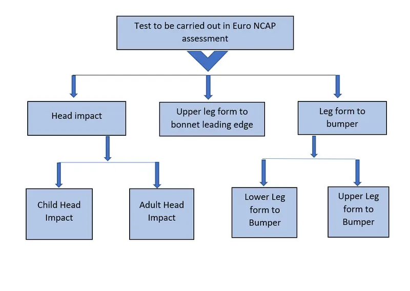
They provide safety performance reports of new cars and awards ‘star rating’ based on the performance of the vehicles in a variety crash tests that includes front, side and pole impacts, offset impacts and pedestrian’s impact.
TESTS CARRIED OUT IN EURO NCAP ASSESSMENT:
PEDESTRIAN IMPACT ZONE:
WRAP AROUND DISTANCE:
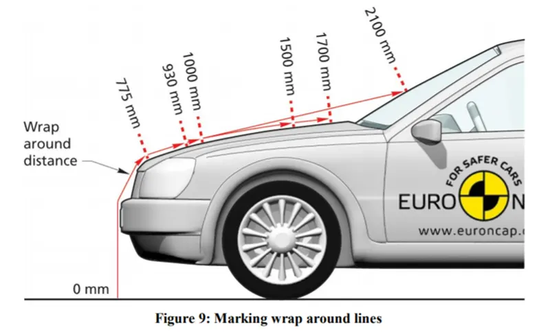
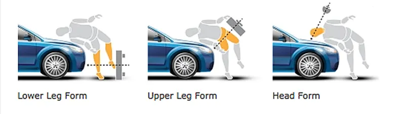
When a car hits a pedestrian, whole human body wraps around the front area of the car. Head impacts either on bonnet or on the wind screen. The distance at which the car from the ground is called wrap around distance.
The wrap around distance is measured from the ground (vertical extension of the foremost centre point of the vehicle) along the outer structure of the vehicle to the pedestrian contact point.
The severity of the injury caused by the frontal crash analysis depends on the,
- Shape of the vehicle.
- Speed of the vehicle.
- Movement of the pedestrian relative to the vehicle.
PESTRIAN HEAD IMPACT ZONE:
During the crash analysis test based on the wrap around distance (WAD), two test zones are created. They are,
- Child head impact zone. (Wrap around distance of child head impact zone is around 1000 – 1500mm.)
- Adult head impact zone. (Wrap around distance of adult head impact zone is around 1500 – 2100mm.)
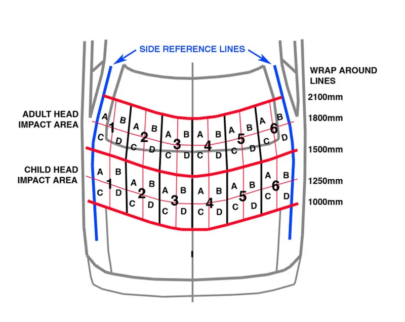
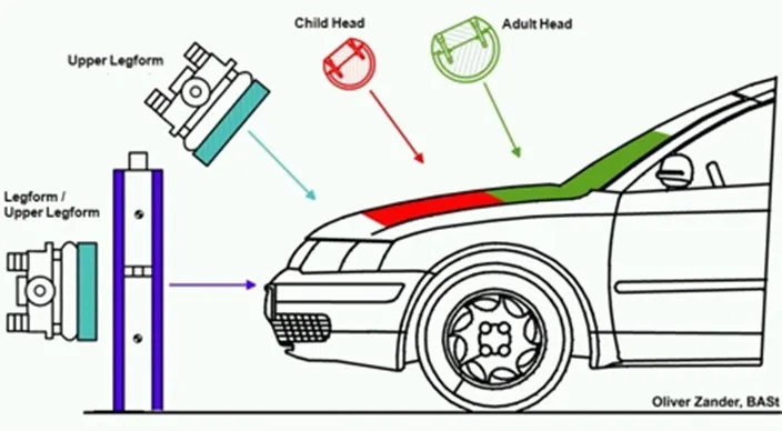
This study helps the hood designer to design the hood outer and inner panel by considering the wrap around distance, child head impact zone and adult impact zone.
The material from the hood inner panel is removed at the required zones such as child head impact zone and adult impact zones.
So even though a car hits a pedestrian, the pedestrian may not get affected severely and the impact should be less by removing the material from inner panel of hood at specified areas.
DIRECTION OF FORCE DISSIPATION:
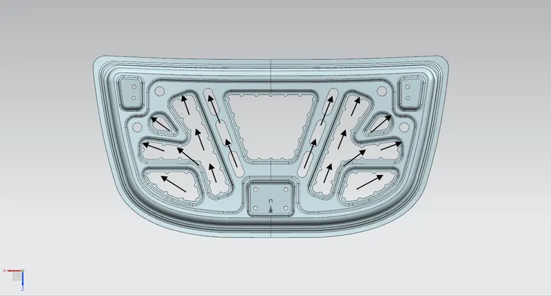
- The main important design consideration of hood inner panel design is to dissipate the force towards the outside to reduce the impact to the passengers inside the cabin when a car goes under collision.
- To reduce the impact to the passengers inside the cabin, the embosses which are created by removing the material are designed in such a way of dissipating the force towards the outside direction.
NVH LEVELS:
- Noise, vibration, and harshness(NVH), also known as noise and vibration (N&V), is the study and modification of the noise and vibration characteristics of vehicles, particularly cars and trucks.
- While noise and vibration can be readily measured, harshnessis a subjective quality, and is measured either via jury evaluations, or with analytical tools that can provide results reflecting human subjective impressions.
- NVH testingis widely used in the automotive industry for the reduction, design, and quality assurance of interior and exterior vehicle noise or vibration. The process usually takes place during the vehicle development of passenger cars.
- NVH can be tonal such as engine noise, or broadband, such as road noiseor wind noise. Basically, it is everything that drivers or passengers can either hear and feel from a car while driving, such as wind noise, road noise, bumps from the suspension, or vibrations from the engine.
Reducing the NVH level caused by hood:
- The NVH caused by hood is reduced by introducing a stiffener pad. This pad is placed between the hood inner panel and the outer panel to increase the strength locally.
- During the motion of the car, the hood will wobble and produces noise and vibrations. So, these noise and vibrations are reduced by using this stiffener pad.
PROCEDURE FOR DESIGNING THE HOOD:
Way of approach:(Bottom-up assembly).
Actually, there are two types of approaches are available to make an assembly. They are, Bottom-up assembly and Top-down assembly. For the hood design assembly, we followed the top-down approach.
Bottom-up assembly:
The bottom-up assembly is the most preferred approach for creating assembly models. In this type of assembly, the components are crated in part design work bench (as NX cad part) file. Parts are conceived in assembly design workbench using product structure tools. After inserting each individual components into the assembly file, constraints are applied to position them accordingly in the 3D space with respect to other components. This assembly is preferred for large assemblies, especially those having an intricate individual component.
Top-down assembly:
In the top-down assembly design approach, the part components are created inside an assembly design workbench. So, there is no need to create a separate part file of individual components. The top-down approach is completely different from the bottom-up assembly approach. Here we need to create a product file first and inside the product file, the individual part components are created. Note that even the part files are created inside a product file, they are saved and opened individually one by one when they are needed. Here the construction and the assembly take place simultaneously.
GIVEN DATA:
HOOD THICKNESS DATA:
- Hood outer panel thickness – 0.75mm.
- Hood inner panel thickness – 0.75mm.
- Reinforcement thickness – 1.5mm.
GIVEN COMPONENTS:
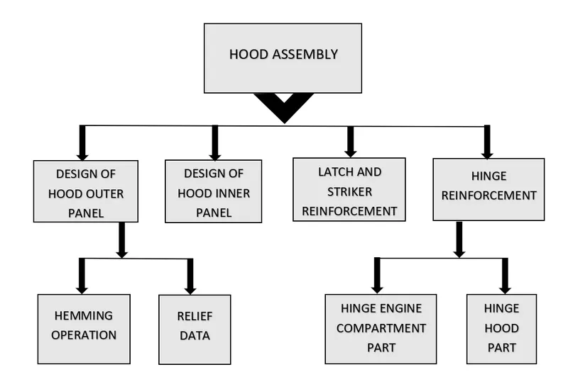
- Hood outer panel.
- Hood hinge assembly.
- Latch and striker
DESIGNING OF INNER PANEL:
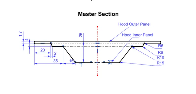
GIVEN MASTERSECTION:
PROCEDURE TO BE FOLLOWED:
- The hood inner panel is created as a part component. We took the reference of hood outer panel to create the hood inner panel.
- The reference panel is offsetted at 0mm and named as working surface. Now the working surface is offsetted to 1.7mm downwards. Now the curve is projected on the offsetted surface for 20mm from the edge by using the command called offset curve in face in the curve tab.
- Now the surface next to the offsetted curve is trimmed by using trim sheet command in the surface tab.
- Now the working surface is offsetted to 5.7mm downwards. The curve is projected on the offsetted face for 22mm towards inside with offset curve on face command. And one more curve is projected on the surface at a distance of 35 towards inner side with the help of offset curve in face command.
- Now the surface before the 22mm offset and surface after 35mm offsetted curve is trimmed by using trim sheet command in surface tab.
- Then the gap between the 1.7mm surface and 5.7mm surface is formed by using through curves command.
- Now the working surface is offsetted to 25mm downwards by using offset surface command.
- Then the curve is offsetted at a distance of 50mm towards inside on the 25mm offsetted surface by using offset curve in face command.
- Now the surface before 50mm on the 25mm offsetted surface is trimmed by using the trim sheet command in surface tab.
- Then the gap between the 5.7mm surface and 25mm surface is filled by using through curves command.
- Now the edges are blended by using the face blend and edge blends commands with the required radius which is mentioned in the given master section.
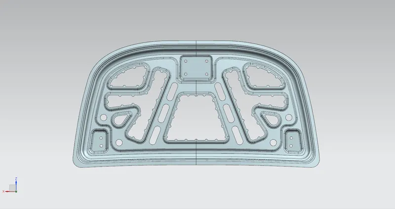
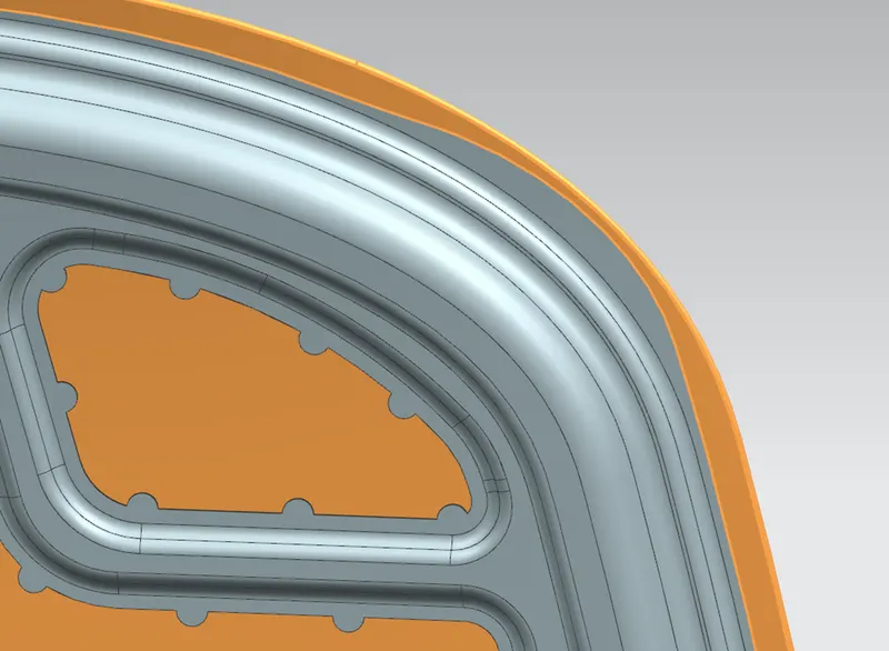
- Now the material on the inner panel is removed on the child head impact zone and adult head impact zone by sketching and trimming the sheet by using trim sheet command.
- And also, the direction of material removal is towards the outside because the force dissipation is towards the outside.
- By removing the material from the inner panel, the strength of the panel is reduced. To improve or to regain the strength of panel, the embosses have been created by the help of law extension and trim sheet commands.
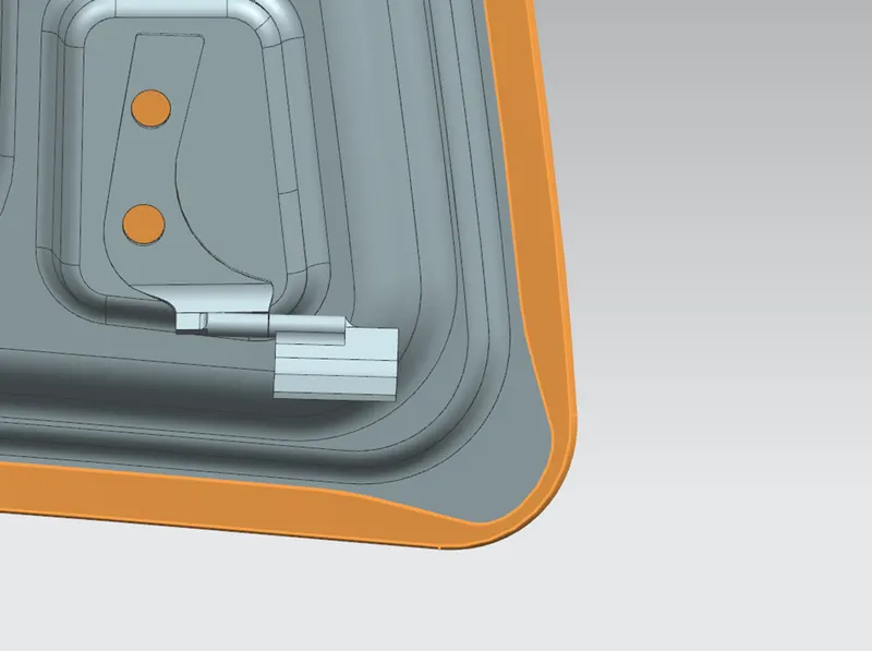
- Then the embosses is also created for hinge assembly and striker positioning on the inner panel.
- The thickness of the hinge assembly and the latch and Stricker reinforcements was 1.5mm
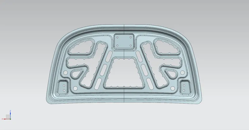
- After that the mastic points are added at the required areas for joining the middle portion of inner panel with the outer panel.
- Now the part is sewed and thickened to 0.75mm and saved as hood inner panel part file.
IMPORTANCE OF MASTIC SEALANTS:
The main purpose of the outer panel required in the hood assembly is for the aesthetic looks. So, we cannot use any welding operations or the bolts to join the outer and inner panel, as this results to the damage of aesthetics of hood outer panel. So, the joining of inner panel and the outer panel is done with the help of hemming operation and mastic sealants.
APPLICATION OF MASTIC SEALANT:
Mastic is a kind of small rubber paste which is introduced between the hood outer panel and inner panel. When this hood goes into the hot bath furnace, its get hardened and joins the hood outer panel and hood inner panel and gives the strength to the hood locally.
DESIGN PROCEDURE OF OUTER PANEL:
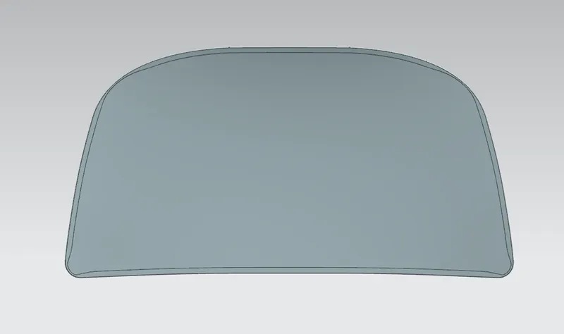
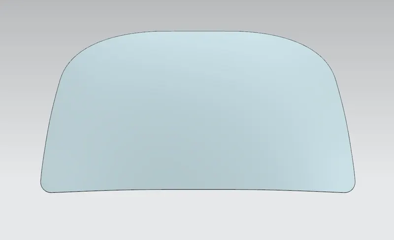
- The given outer panel is offsetted to 0mm by using the offset surface command. Then it is added into feature group as a working surface.
- Then the original panel is hided and the edge of the surface panel is offsetted to a required distance for creating a hem for the outer panel by using the offset curve in face command.
- Now the working surface is offsetted to required distance and trimmed the required portion according to the master section.
- Now the law extension is created for hem and a hemming is created with the help of face blend (three face fillet option).
- The hood outer panel is thickened to 0.75mm.
LATCH AND STRIKER:
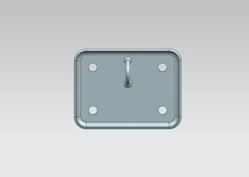
- A latch is basically a fastener that keeps the hood closed shut. This latch ensures that hood is securely connected to the vehicle and it doesn’t open unexpectedly.
- An engine hood latch mechanism is for locking an engine hood in a closed position includes a striker fixed to the lower surface of an engine hood and a base member having a vertical slit into which the striker is dropped in response to closure of the engine hood.
- A locking mechanism engages with the striker in response to drop the striker into the vertical slit and locks the striker in a closing position where it holds the engine hood in the closed position.
- When a latch and striker is attached to the hood inner panel, the strength of the panel is reduced. To regain that strength of the panel, reinforcements are used.
HINGE ASSEMBLY:
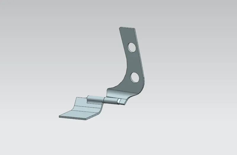
- The hinge assembly is a mechanism that makes it possible for you to open and close your hood. This hinge assembly allows the hood panel to move up and down similar to the other doors.
- Each car has a pair of hinge assembly (driver and passenger sides) which is installed in the front of the vehicle.
ASSEMBLY OF HOOD:
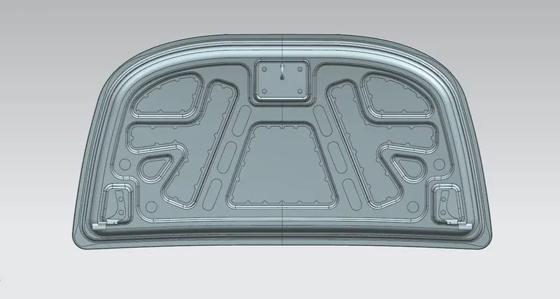
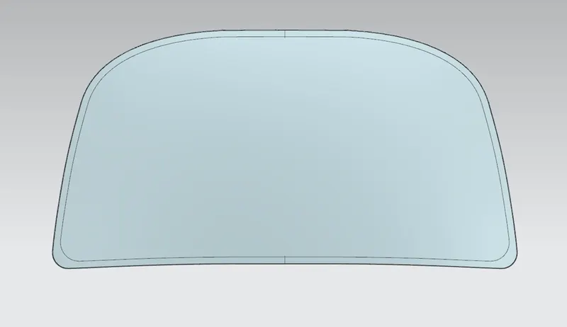
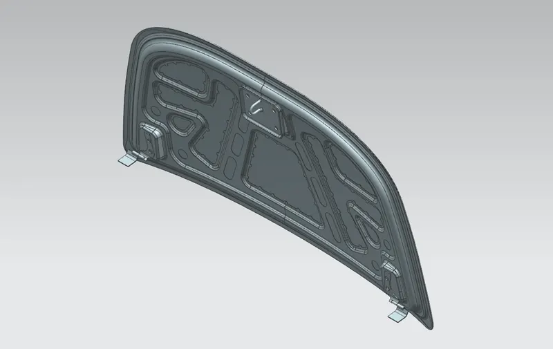
- Now the assembly product file of hood is created and saved as a “Hood assembly”. Then the individual part components required for hood assembly know as hood inner panel, hood outer panel, latch and striker, hinge reinforcements are added into the Hood assembly product file.
- Then the assembly is done by giving the required assembly constraints to all the components.
HEMMING PROCESS:
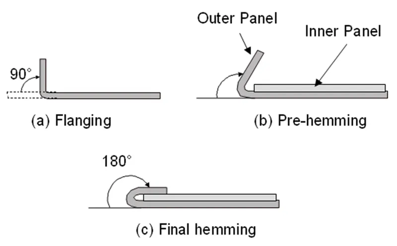
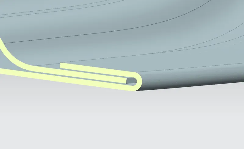
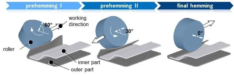
- Hemming is a forming operation in which the edges of the sheet are folded or folded over another part in order to achieve a tight fit. Normally hemming operations are used to connect parts together, to improve the appearance of a part and to reinforce part edges.
- In car part production, hemming is used in assembly as a secondary operation after deep drawing, trimming and flanging operations to join two sheet metal parts (outer and inner) together. Typical parts for this type of assembly are hoods, doors, trunk lids and fenders.
Types of hemming:
- Open hemming.
- Roll hemming.
- Tear drop hemming.
- Closed hemming.
Roll hemming:
RELIEF DATA:
DEEP DRAWING PROCESS:
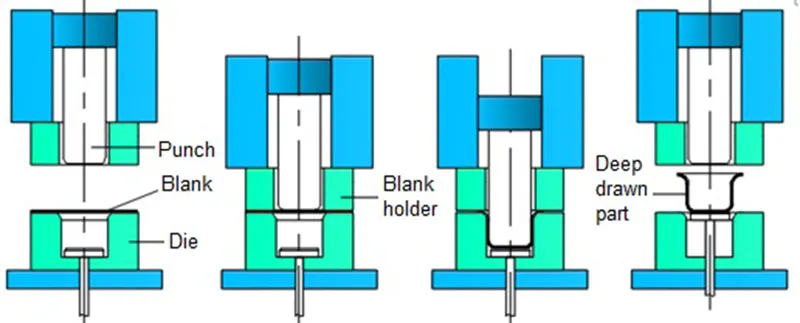
Deep drawing is a sheet metal forming process in which a sheet metal blank is radially drawn into a forming die by the mechanical action of a punch. It is thus a shape transformation process with material retention. The process is considered "deep" drawing when the depth of the drawn part exceeds its diameter.
HINGE AND STRIKER POSITIONING:
- For a proper opening and closing of hood, latch and striker should be positioned at a required position.
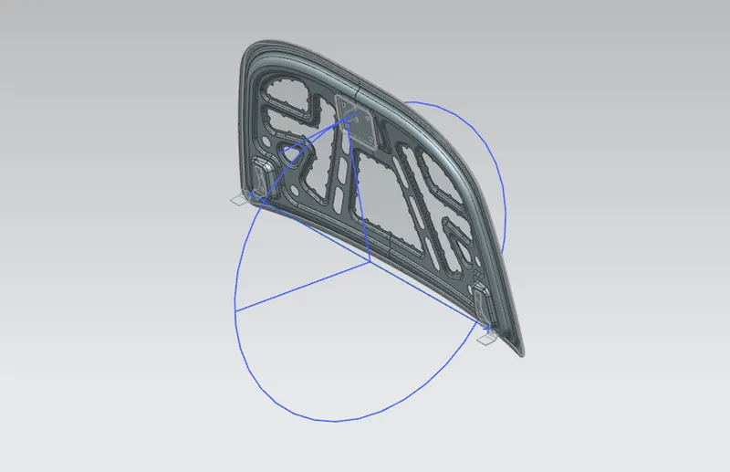
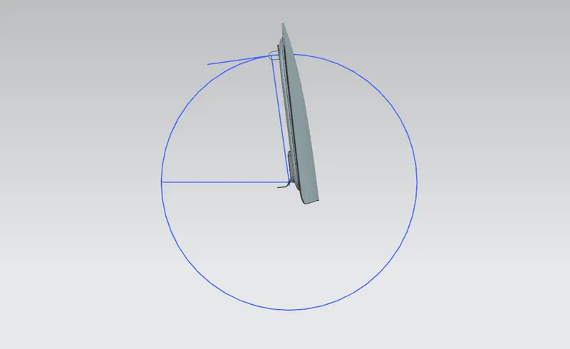
- For positioning the latch and striker on the hood inner panel, a reference line is drawn between the two hinges and a circle is drawn by taking the hinge axis centre point as a centre of the circle.
- Now a datum plane is created on the latch and a line is created which is perpendicular to the latch.
- Then the latch and striker positioned at a required area on the hood inner panel with the help of perpendicular line of latch with the circle which is already drawn.
- Once the latch and striker is position at required area on the hood inner panel, an emboss for latch and striker is created on inner panel by extracting the face of the latch.
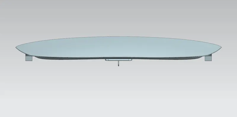
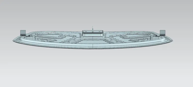
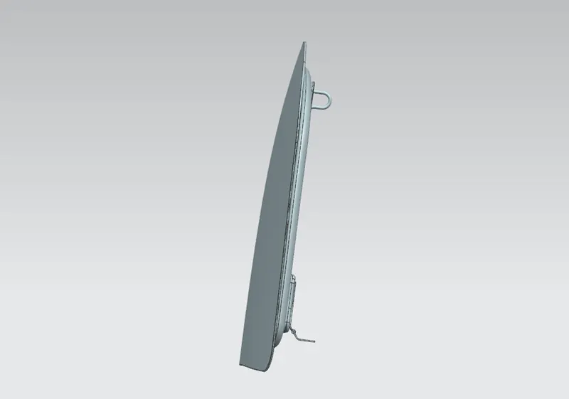
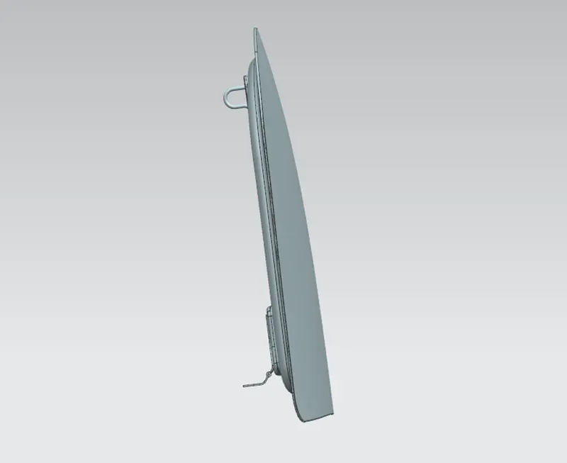
HOOD ASSEMBLY VIEWS:
FRONT VIEW:
BACK VIEW:
TOP VIEW:
BOTTOM VIEW:
LEFT SIDE VIEW:
RIGHT SIDE VIEW:
ISOMETRIC VIEW:
CONCLUSION:
Finally, the design and assembly of hood is done by using NX cad software by following Euro NCAP regulations and some important parameters like emboss design, hinge axis, trajectory of hood, direction of force dissipation, front and rear relief, mastic data, etc.