Hood design-Week 2
Hood Design
By
Santhosh Sivan.G
Introduction
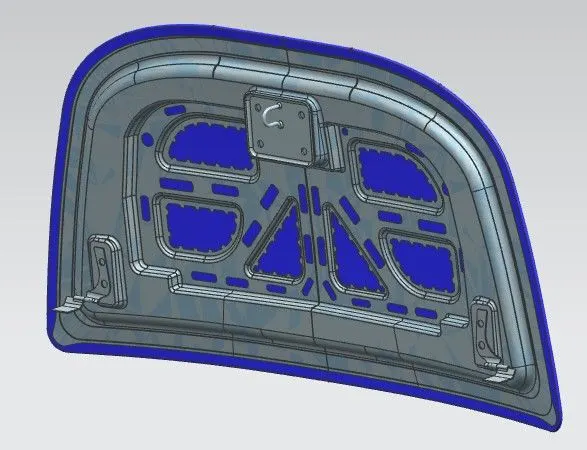
Hood is also referred as a bonnet in some other countries. It hinged over the engine compartment in front engine vehicle. It allows the engine compartment for doing maintenance and repair work. Front Engine car the hood may be hinged either the front or a rear edge. The Hood we can split in to two sections one is inner and another one is outer panel. The future variant both sections are combined and mounted with the help of hinge.
The purpose of inner panel is to cover the engine parts, wiring and some other components from physical damage and also it reduces noise comes from engine with help of reinforcement (form under body coating). The purpose of outer panel gives a good finish of the vehicle and it protect the inner panel from dent, moisture, etc.
We can see how to create hood in step-by-step process. Below following are tools used for creating hood.
- Wave Geometry Linker
- Offset surface
- Trim sheet
- Through curve
- Law extension
- Trim and Extension
- Face blend
- Edge blend
- Project curve
- Emboss
- Mirror Assembly
- Extract sheet
- Sew
- Examine Geometry
This are following tools used for creating a hood
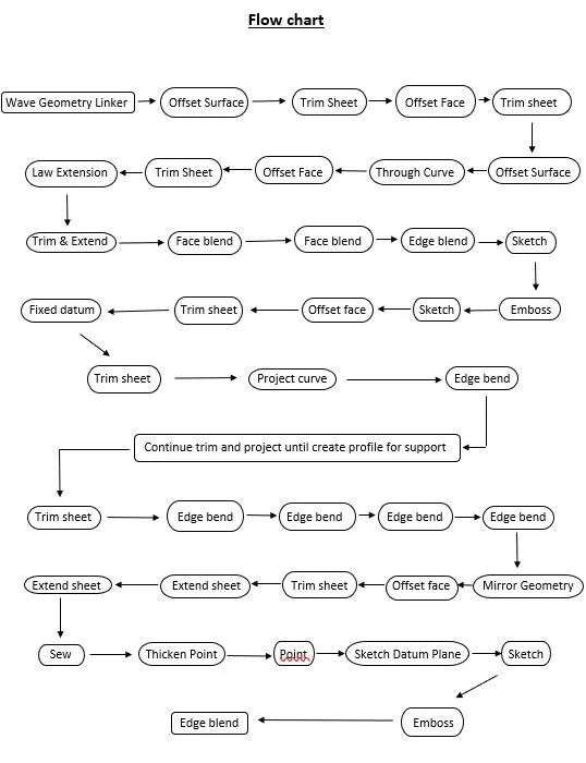
This are the following Tools use to creating the hood assembly.
Wave Geometry Linker:
Wave geometry linker which means copy the part from other part in assembly into the work part and note after copy the face of hood and any other assembly component deselect associative. Associative means if to make any change in while creating any new part or modifying existing part it will affect your assembly if deselect there is no change done in your assembly file if you make any changes
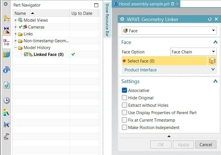
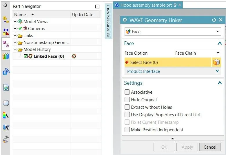
With associative Without associative
Offset Surface:
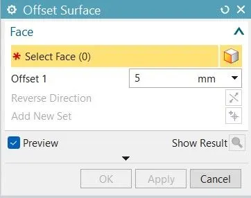
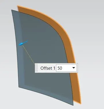
Offset surface means to create a one or more body by offsetting it by particular value. The result is a new body with an offset relation to the chosen faces. Also, the specified distance called as offset distance. You can select any kind of face for creating an offset. For creating offset command by select offset icon in the surface tab or select insert-->offset/scale-->Offset surface.
Trim sheet:
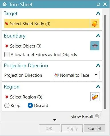
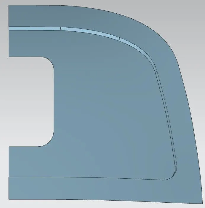
Trim sheet means to remove excessive or unused portion from the part. Use the Trimmed Sheet command or select Insert-->Trim-->Trim sheet to trim sheet bodies to intersecting faces and datums, and projected curves and edges.
Through Curves:
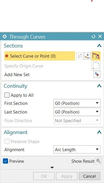
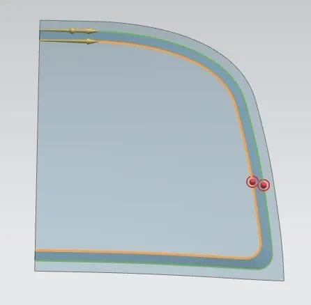
Through curve means nothing but to create a body through multiple sections where the shape changes to pass through each section. Section curves are like points, solid edges, solid faces, etc. Each curve needs a direction. So that you can change the direction by clicking the reverse option on through curve dialogue box. Click or select through curve on surface tab or select Insert-->Mesh surface-->Through curve.
Law Extension:
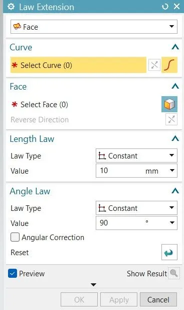
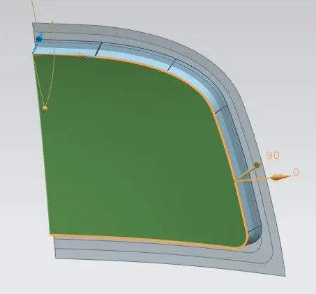
Law Extension which means to extend an existing surface or sheet based on distance and the angle of the extension. It creates flanges or extension which perpendicular direction or it necessary to reference the existing face. By selection law extension command on surface tab or select Insert-->Flange surface-->law Extension.
Trim and Extend:
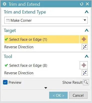
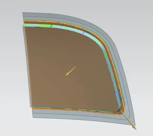
Trim and extend means a set of edges or faces to intersect with another edge or faces. This option you can extend or trim one or more surface using a set of tool object. Select or click trim and extend option on feature tool bar or select Insert--> Trim-->Trim and Extend.
Face Blend:
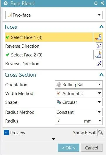
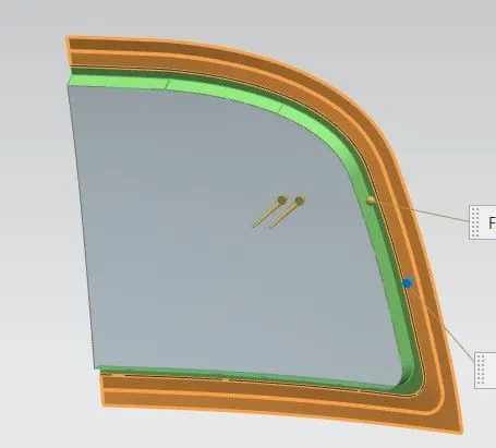
It means to remove the corner (edge) from the component by selection the faces. Tangent blends between the set of selected faces the bend should be conic or circular or law controlled. By selecting face blend on Surface tab or select Insert--> Detail feature-->Face blend.
Edge Blend:
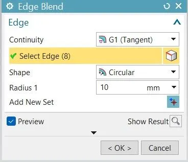
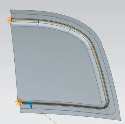
The edge blend means to remove corner form the portion by selecting each edge in the part and the radius should be constant or variable. By select the edge blend command or select Insert-->Detail feature-->Edge blend.
Project curve:
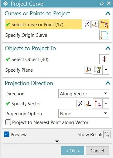
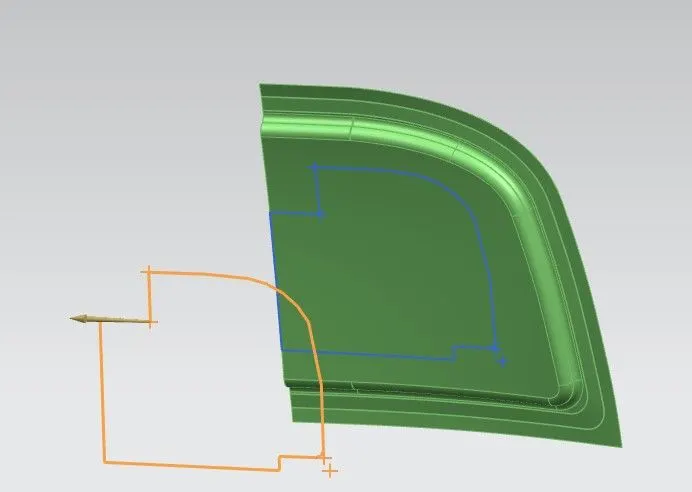
Project curve is to project the curve, edge and points into the face or the plane. You can project the curve associatively or non-associative onto a sketch also create a constraint between projected curves and non-projected curves. Note: the non-associative curves can move based on sketch constraints. But associative curve is always fixed. By selecting Insert-->Sketch curve-->Project curve or simply click project curve option.
Emboss:
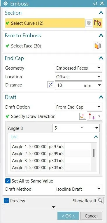
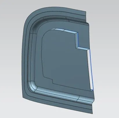
Emboss means a body with face made by projecting a section along the vector with option for endcap location and shape. By selecting emboss on surface->More-->Emboss or select Inser-->Design Feature-->Emboss.
Sketch:
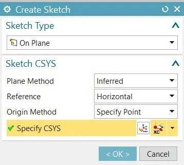
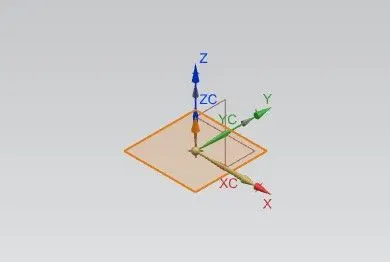
Sketch is nothing but to create new part or modify a existing part with the help of datum plane, face or edge. They are different type of direct tools present on sketch they are curve, line, point, rectangle, circle, etc. In the current application use the direct tool to add curve, line, point, etc. To create a sketch simply click sketch option and select plane or select insert-->sketch.
Mirror Geometry:
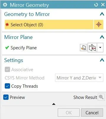
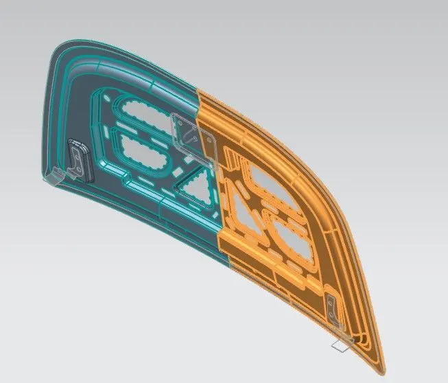
Mirror geometry means to create an existing part with in the plane or respective axis by selecting the whole part i.e., copy the geometry and mirror them across the plane or an axis. For create a part across the plane, simply click mirror geometry in surface tab or go to Inser-->Associative cop-->Mirror geometry.
Sew:
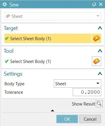
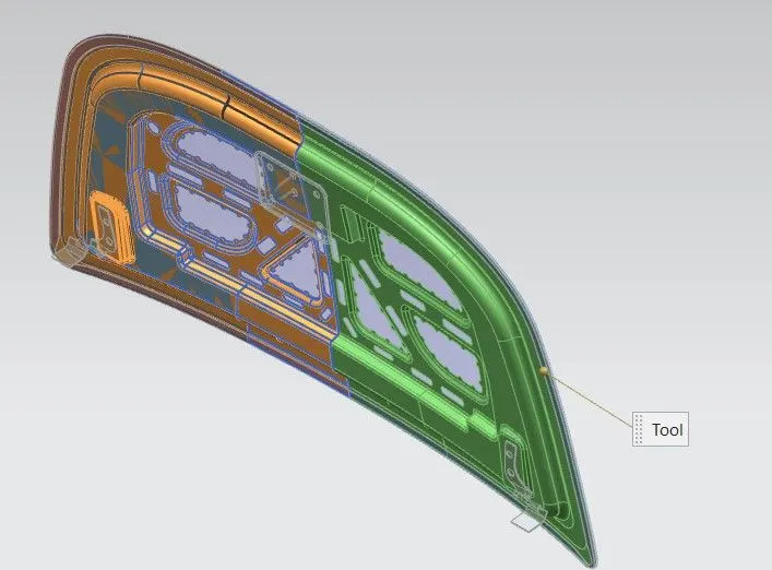
Sew means to combine two parts into single part i.e., combine the both bodies by sewing common edges together or combine solid bodies by sewing common faces. To apply the sew by click sew option in surface tab or select Insert-->Combine-->Sew.
Extend Sheet:
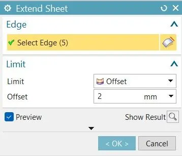
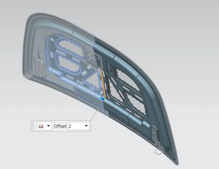
Extend sheet is to extend the sheet at particular distance or to intersect with another body. For extend sheet create the line and select extract sheet option in surface tab or select Insert-->Trim-->Extract sheet then select the line, give particular distance for extend and click ok.
Examine Geometry:
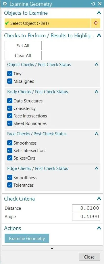
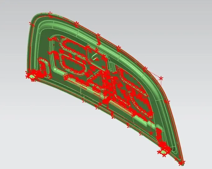
Examine geometry which means to analysis the part for the intersect condition. In this command we can also analysis intersection, smoothness, tolerance and some other entities. This is one of common tool used in automobile industry. Because we can identify any error present in the designed part easily and also the designed part should be passed this feature otherwise the design not permitted (error shown as different colour example: Red). For examine geometry select insert-->Analysis-->Examine geometry or click examine geometry on analysis tab.
Mastic point:
Mastic Point means the area which hood inner panel fixed with outer panel using a mastic glue. The purpose of mastic glue hold (keep) the inner panel stuck into the outer panel. In outer panel not able to welt or install the bolt because the outer panel provide precious look to the car. So, this as to be done with the help of mastic sealant. The sealant is elastic component which act as rubber.
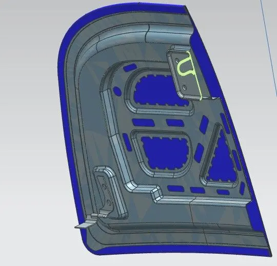
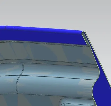
Hemming:
Hemming means sheet metal forming process in which the sheet is joined by bending 1800 . Automotive body panel and automotive parts such as doors, hood and some other parts formed by hemming process. In this process usually the sheet bended with inner panel and outer sheets. For hemming click
Position of Hinge and striker (latch Trajectory):
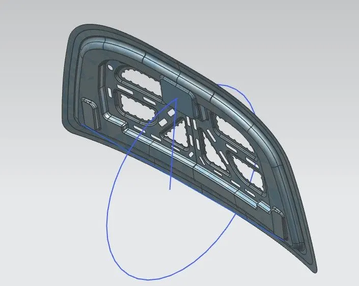
Position of hinge and striker means to place the striker on the hood parallel to the x-axis and also the position of striker should be perpendicular to the trajectory of the hood inner panel. How we can position the hinge and striker. Place the striker behind the hood or where you have to place. Then give a parallel constrain with respect to x-axis and create the emboss for where you place the striker. Finally give touch constrain. For hinge mark two point and follow same procedure after creating a line and circle. Note: the line should be tangent for the circle.
Design for reinforcement:
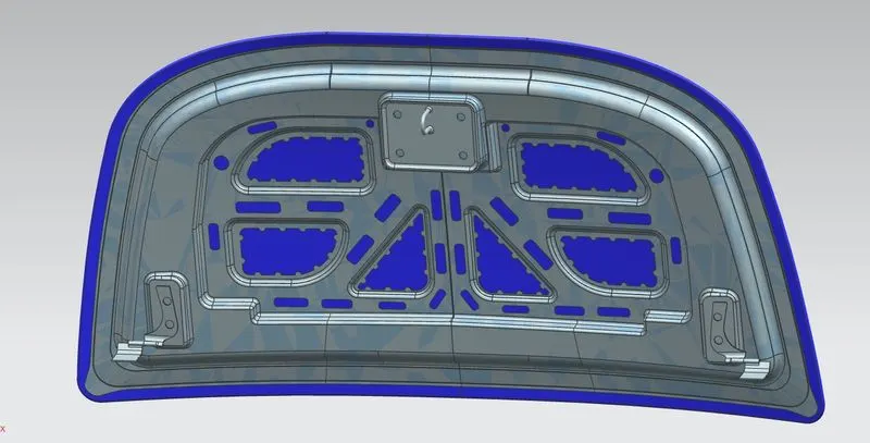
Design for reinforcement nothing but, to gives an extra strength to the hood and also provide a provision for hood and striker mount.
Mastic Data:
Mastic data means the point of the hood inner panel should contact with hood outer panel with the help of sealant. Also, to minimise the vibration and noise comes from the engine.
Diameter of the mastic point is 5mm, distance should 5mm.
Manufacturing process:
In manufacturing process, note the design should be fulfil all design requirements and to absorb impact while vehicle collision and also the using metal should be light in weight.
The hood should not have any sharp edges and negative draft.
Outer and inner panel thickness should be 0.75 and the reinforcement should be 1.5mm.
Hood Design:
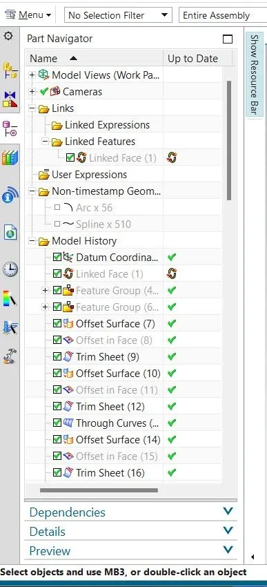
In hood design first open the outer panel and use wave geometry linker for creating same existing part in another part file. After creating the new part with existing one give offset command for offset the sheet at particular distance for creating hood shape
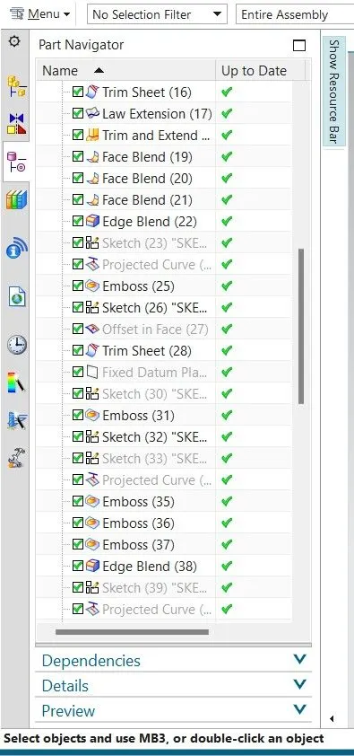
Then give offset face and trim command for creating the outer part. Once again give offset surface, face and trim sheet command for creating hood profile. Through curve option used to link the both parts. Law extension command use to extend the selected edges in to vertically. Remove the intersected edges with the help of trim command
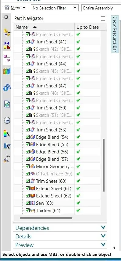
After that remove sharp edges from the part by using edge bend and face bend command. After removing edges from the part, create the sketch with respect to x-axis. And apply project curve to project the sketch on the part for creating emboss. After that give emboss to the hood. Again, make the sketch for provide curve shape in the hood corner. Apply trim sheet for removing unused part
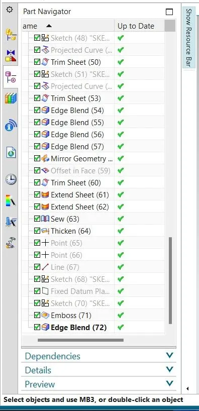
Create sketch and apply emboss for mounting the striker assembly. Again, create sketch for providing extra support or profile look to the flange and apply project curve. Then create emboss and apply edge blend for removing sharp edges. Same process done before emboss, instead of that give trim sheet and apply mirror geometry. Give sew command for combine two parts into single one. Note: Give examine geometry for analysis the properties (geometry) like tolerance, intersection, smoothness, etc. after that apply thicken of about 0.75 mm. In this part make hemming for providing good look to the
hood. In case you change the outer panel colour right click on the hood and select assign feature colour and select required one.
Hood Inner panel design:
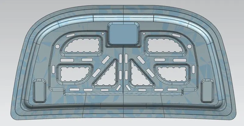
Front view:
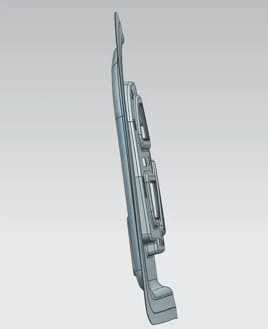
Right side view:
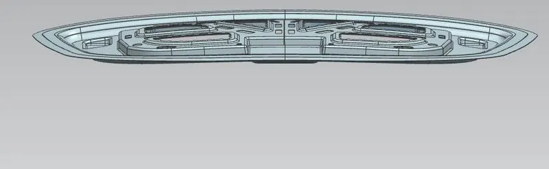
Top View:
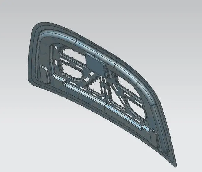
Isometric view:
History tree:
Hood Assembly:
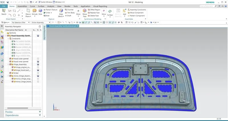
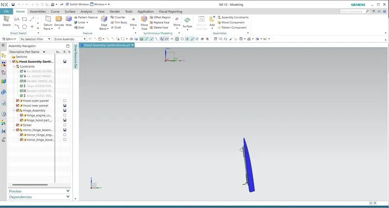
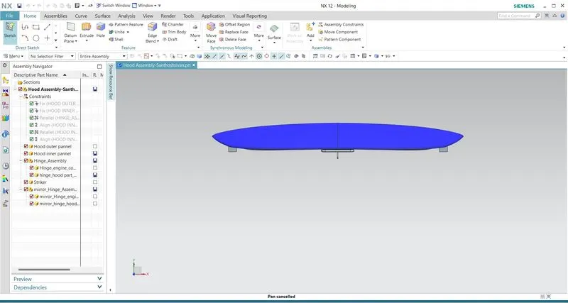
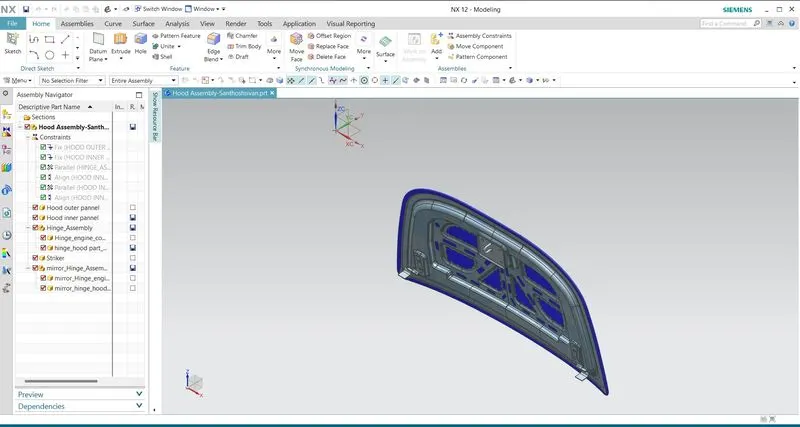
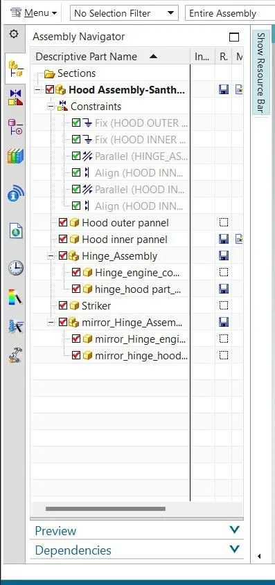
Hood assembly, insert the outer panel and apply constrain then insert inner panel with respect datum plain and apply constrain. After inserting the inner and outer panel then insert hinge and striker also. Use move command to move the striker and place It where you want to fix it. Give parallel constrain to the hinge axis with respect to x-axis
Then apply touch constrain between wo faces one is striker back face another one is hood emboss face or give partial touch constrain. Here use, mirror assembly command for striker. Click mirror assembly command and select the striker then click next. Now select the plane and click next. Again, click next option then select the striker and click associative then click next and finish. Now striker as assemble both the edges.
Same process done for hinge mounting without mirror assembly. Before apply constrain For, placing the hinge to the hood, draw the circle and create point on both the striker by selecting the round edge. Draw the line and connect both points. Then, draw the line vertically, make sure the drawn line should be tangent to the circle.
Hood Design:
Front view:
Right side view:
Top View:
Isometric view:
History tree:
Conclusion:
The hood design as completed in NX 12. While creating hood I understood process, function of the tools which was used to create. Also, I learned how assemble the parts in the hood like inner panel, Striker and hinge.