Hood design-Week 2
HOOD DESIGN
Now as we are all familiar what benchmarking and underbody coating is, and how this processes are executed in the OEM’s. So now depending on that as we proceed further in this coursework, we need to learn from the basic what is the automotive sheet metal? , how it is designed and manufactured according to the design rules and considerations.
So now initially we get to:-
- What is sheet metal design?
- Sheet metal design is nothing but the process of forming the different parts from the sheet metal by punching, stamping, cutting, bending etc.
- Mainly the basic structure i.e the chassis of the vehicle is designed and manufactured using sheet metal.
- This is somewhat similar to the plastic design but here the design rules and the material used to manufacture is different.
- Here the Class A Surface is provided i.e the sheet metal and we need to create the Class B Surface, but here the Class C Surface is not created to join Class A and B Surface. In place of Class C here the joining process is done called hemming.
- Hemming is the process in which the edges of sheet metal of Class A are twisted and bend around the B Surface in order to grip the inner surface. This process is water tight i.e leak proof.
So now we got to know what actually is the sheet metal design, and how the parts are manufactured.
So based on to this, we got the Challenge to design the hood of the automotive vehicle.
But before we start the design of the hood we need to study the part in detail, like what is hood, what are all the considerations that we need to take while designing the hood.
- What is hood?
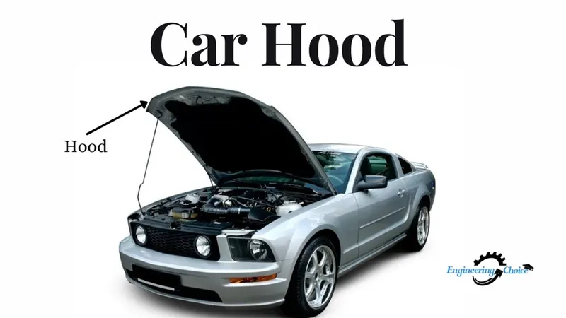
- The car hood is also known as the bonnet. It is basically the part in the front of the vehicle that rests over the engine. The purpose of the hood is that it gives easy access to the engine and the other parts for the maintenance and repair. The hood is shown in the figure below.
Now as we all know what the hood is, we need to study the considerations that are taken to design the hood. What are the design aspects that are studied before designing the hood.
The hood design is one of the important design of the automotive. Here so many aspects of the design are taken into the considerations, for designing of hood.
The basic criteria to design hood is as follows i.e it should follow all given points while designing:-
- NVH
- GAS STAY OR THE SUPPORTING ROD
- LATCH AND STRIKER POINT
- HINGE AXIS
- DEFORMABLE BRACKETS
- PEDISTRAINTS RATING
- EURO – NCAP REGULATIONS
Any of the designed hood should follow the above criteria, only then it is eligible to manufacture and is consider as the safe design.
Let’s study the criteria one by one:-
- NVH :- NVH is basically the noise, vibration and hardness. This is very necessary criteria, in which the mastic sealants are placed between the inner panel and outer panel of the hood. Mastic seal is the hard rubber seal which has the tendency of improving the strength locally around the 80mm diameter. It also controls the vibrations as well as the noise at certain limit. To control the noise and the vibration of hood outer panel the stiffener pad is also mounted.
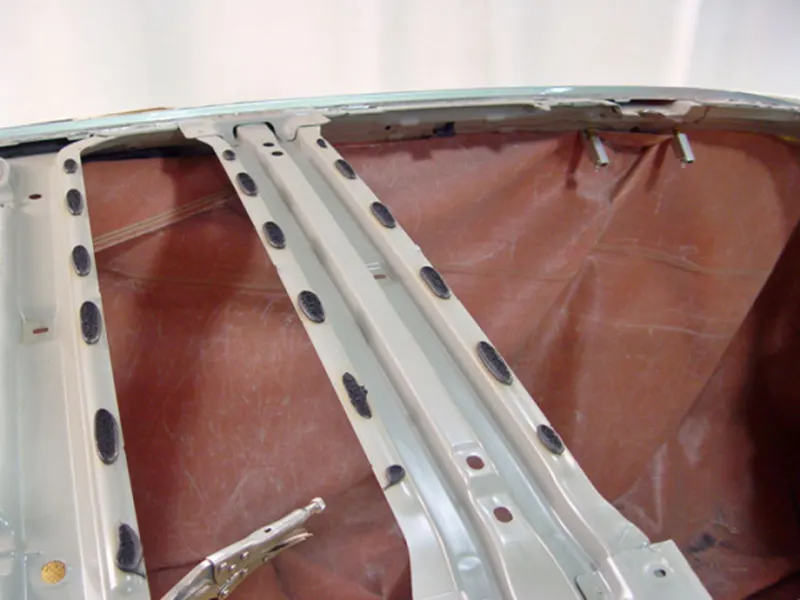
The mastic sealant.
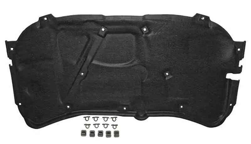
The stiffener pad.
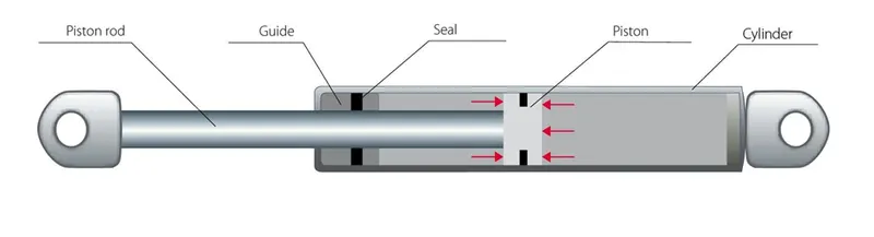
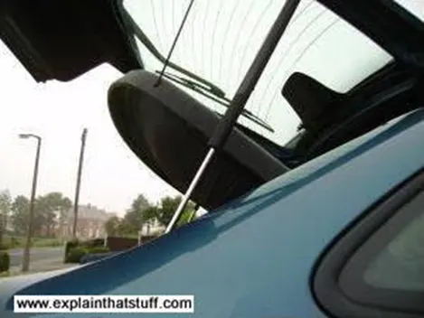
- GAS STAY OR SUPPORTING ROD MECHANISM:- So as a design engineer we should be aware of the hood design, how we are going to design the hood and what should be supporting the hood when it is in open condition. So here for the support two mechanism can be designed i.e the gas stay mechanism and the support rod mechanism. As a design engineer it depends on us which we want in our hood design. The gas stay mechanism uses the compressed gas filled cylinder controlled by the moving piston. It can with stand the external force and gets extended unless a force parallel to the piston shaft is applied as shown in the figure below.
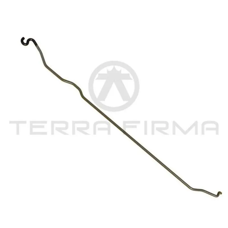
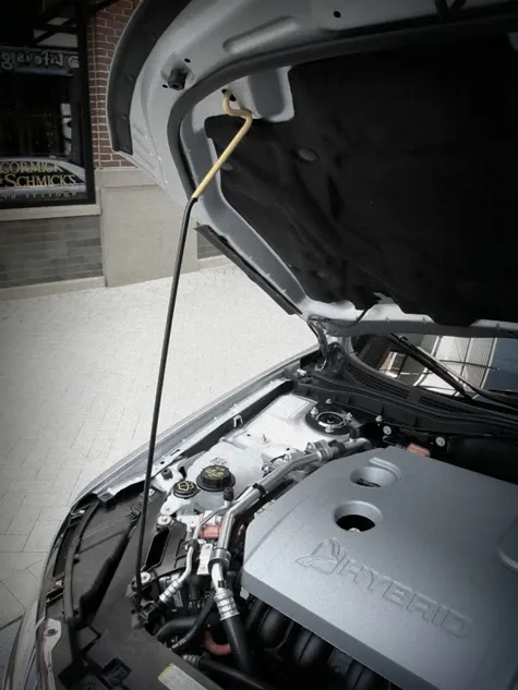
The second is the supporting rod which is placed manually after the hood is opened. This rod is designed in such a way that it can hold the hood at an angle without getting bend or losing the strength as shown in the figure below.
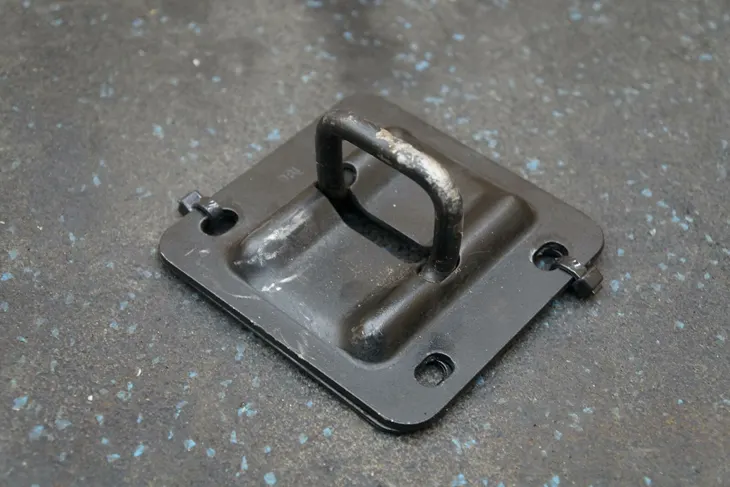
- LATCH AND STRIKER POINT:- Latch and striker point is one of the main point of the hood assembly as it is the closing point of the hood where it gets lock on to the hook tightly. Here we need to calculate according to the axis of the hinge, that where actually the striker and latch will get mounted. Here as the latch is mounted the strength may get loose so in addition we need to add some reinforcement to provide the strength.
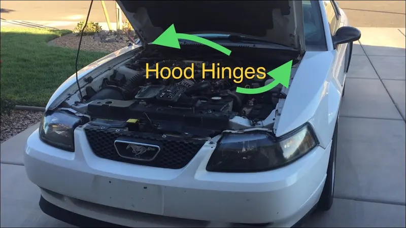
- HINGE AXIS :- Hinge is itself the assembly of two parts which together makes the mechanism. Hinge is the part which is mounted on to the lower part of the hood on to the both sides in order to provide the motion to the hood. Hinge is to be placed roughly on to the hood to find the striker trajectory so that the mechanism could work easier.
- DEFORMABLE BRACKETS :- Deformable Brackets are mounted inside the hood on to the engine compartment. This has to be mounted because in future if any of the frontal collusion occurs with the pedestrian, so as he hits on to the hood the brackets may get deform and it may lead the less damage to the pedestrians. This has to be considered during the design of hood.
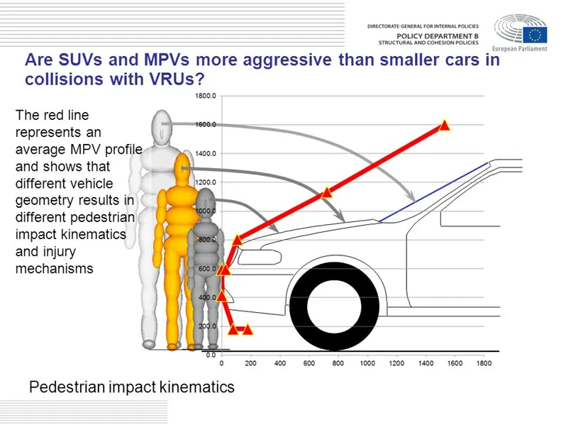
- PEDESTRIANS RATING AND EURO – NCAP REGULATIONS :- Now here comes the important part which gives the rating to the design according to the safety.
Now in most of the countries the majority of the people witness the accidents on road due to negligence of the driver and pedestrians as well. Initially in the automotive industries the safety of the driver was on the priority and the pedestrians were neglected. But now according to the EURO – NCAP Regulations every vehicle is provided with the safety rating. EURO – NCAP says that the hood should be designed in such a way that even in the worst case the child head impact zone and the adult head impact zone should range from 1000WAD to 1500WAD for child and 1500WAD to 2100WAD for adult.
Basically the hood are of the two types
- Inlaid hood
- Wrap around hood
For calculating the head impact assessment a 45 degree reference line is drawn from the ground on to the vehicle. If the reference line lies on to the fender then the wrap around distance is big with the small head impact zone for both the adult and child. But if the point of the reference line falls on to the hood then the wrap around distance will be less and the head impact zone will be high for both adult and the child.
Now as we get the skin data the basic information the hood Class A Surface will be offset 90mm inside the engine compartment.
If the interference occurs the more with the engine compartment then we will get the more red zones because the impact will be directly on to the harder part of the engine. But if the interference of the offset hood skin occurs less with the engine compartment then our design will the more green zones.
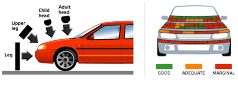
Now what is red zones and green zones. They are basically the impact zone the green zone is the zone where the impact is very less. And the red zone is the zone where the impact is very more.
To be more precise, the more the green zone we will have, the more the safer design will be and will get the better rating.
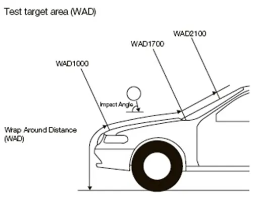
The wrap around distance.
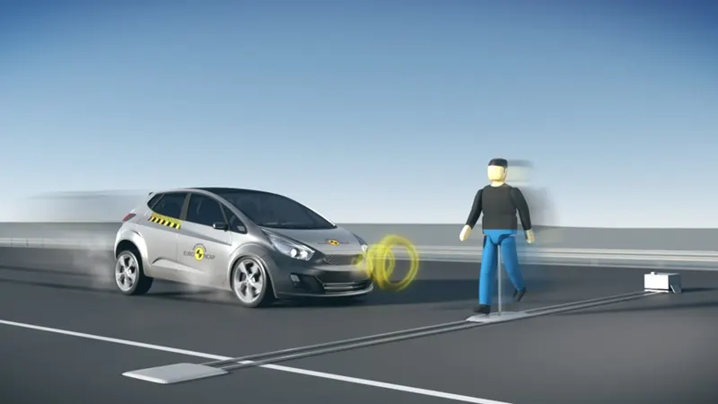
The head impact for the child and the adult is calculated and is practically done on to the maniquin for the multiple times and then the final results are concluded.
Well apart from this now as the technology is doing progress day by day, the automation in the vehicles is also increasing rapidly. Various vehicles have the sensors along with the 360 degree view camera, that they can sense the pedestrians from the certain distance and the speed is lowered automatically or even the vehicle gets stop. This is not our area of study in this challenge it was just the additional information that how the safety measures of the drivers as well as the pedestrians are given the priority.
Well now we all know what hood is and we have studied all the criteria that goes in detail study of what safety measures should be considered in designing the hood, so now let’s jump into the designing of the hood and then assembly of hood.
Here our challenge starts, we are given the Class A Surface of the hood i.e the sheet metal, hinge assembly and the latch and striker part and we need to design the inner panel along with the outer panel considering the rules and regulations and then finally assemble the parts.
So the Class A Surface i.e the sheet metal part is given as shown in the figure below :-
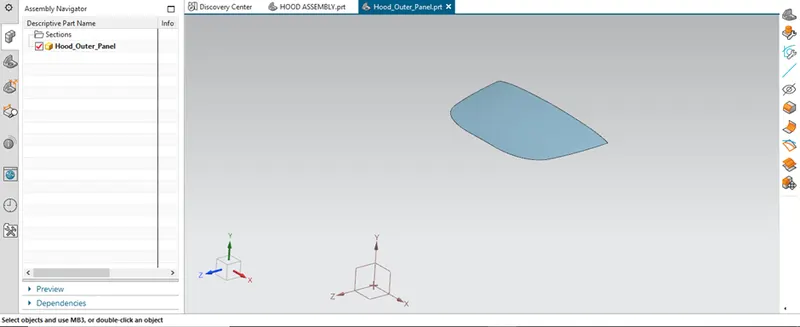
The hood outer panel.
We are going to design this part using the Siemens NX CAD software.
So now along with the part the master section is also provided for us to design the inner panel as shown in the figure below.
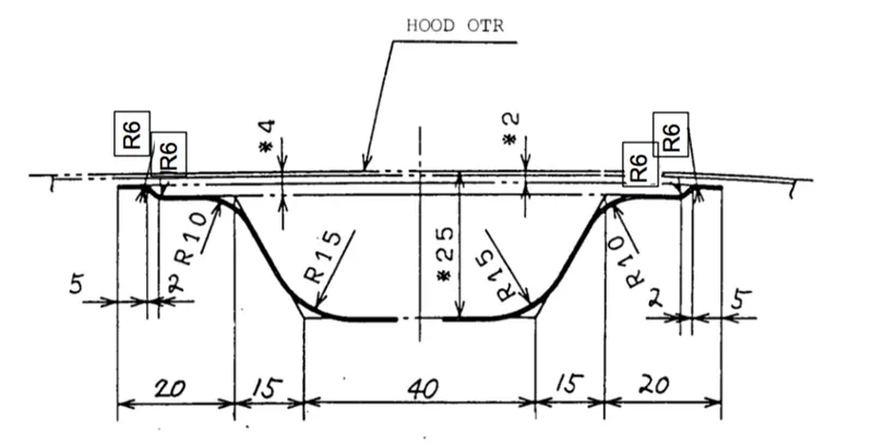
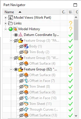
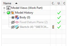
Now here the main hood outer panel is kept in the feature group named the parent file and the same hood is offset to 0mm in order to create the separate hood apart from the parent file.
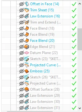
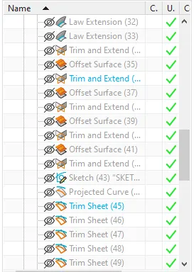
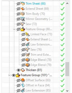
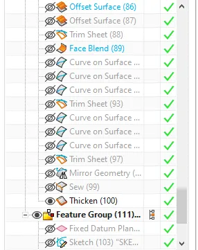
So initially according to the masters section, here the inner panel is designed. The surface is offset to 2mm, 4mm and then to 25mm. And then the trim surface option is used to give the required shape as shown in the figure below.
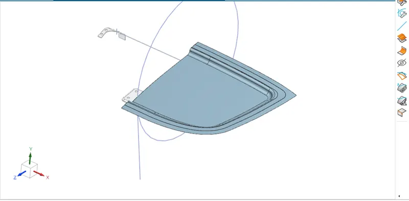
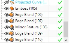
Then the emboss command is used to create the surface for the inner panel design as shown in the figure below.
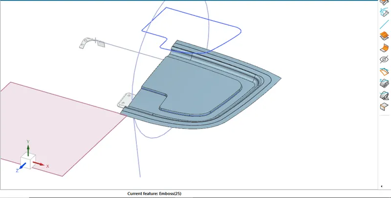
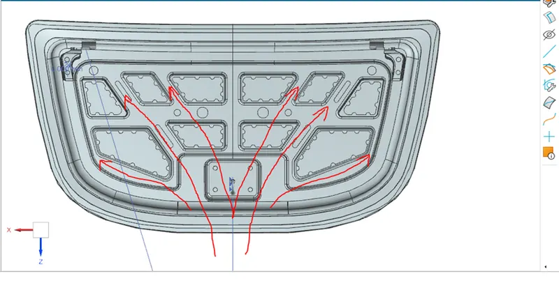
Now here comes the task for us, as a design engineer we need to create the inner emboss design in such a way that all the frontal impact forces applied on to the hood should get dissipated on to the direction of the hinge assembly i.e in the Y direction without getting direct impact on the driver’s side.
So the hood inner design is done as shown in the figure below, but here instead of emboss the law extension command is used.
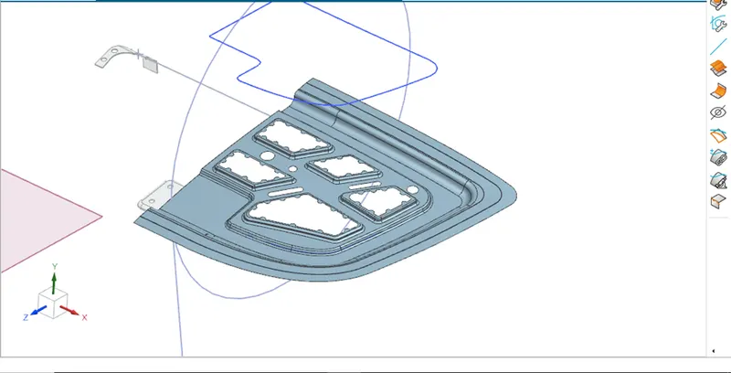
Now this entire geometry is mirrored on to the other side as shown in the figure below.
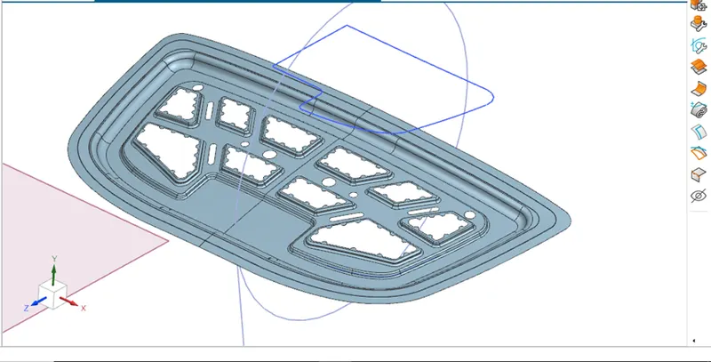
Now this entire geometry is thicken of about 0.75mm as given in the input provided.
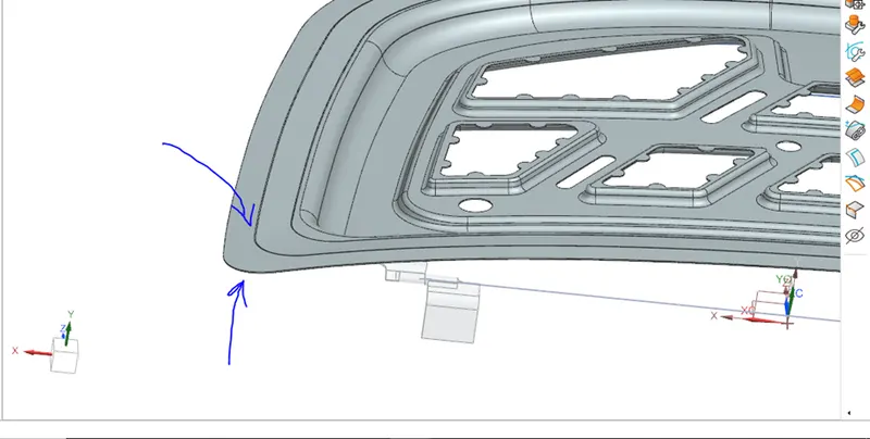
Hence our inner panel design is completed.
Now we need to design the outer panel hemming that will hold the inner panel. So here as provided in the master section given below we need the tolerance of 0.2mm and the hemming distance of 6mm as shown in the figure below.
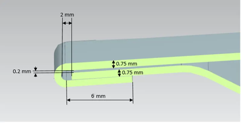
The given below figure is the masters section.
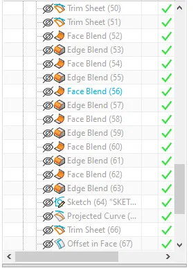
So as per the given instructions the hemming flange is created as shown in the figure below.
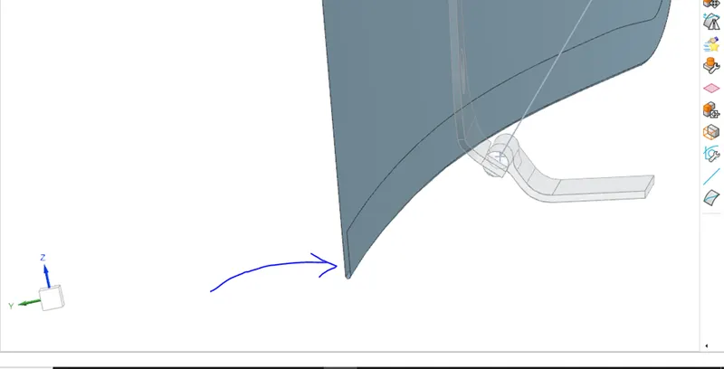
The hemming flange.
Here we need to be careful that the hemming relief should be given at the corners because as the ball rollers bends the sheet around the inner panel, the sheet at the corners may result in changing the shape due to the pressure of the ball rollers. So the relief is provided as shown in the figure below.
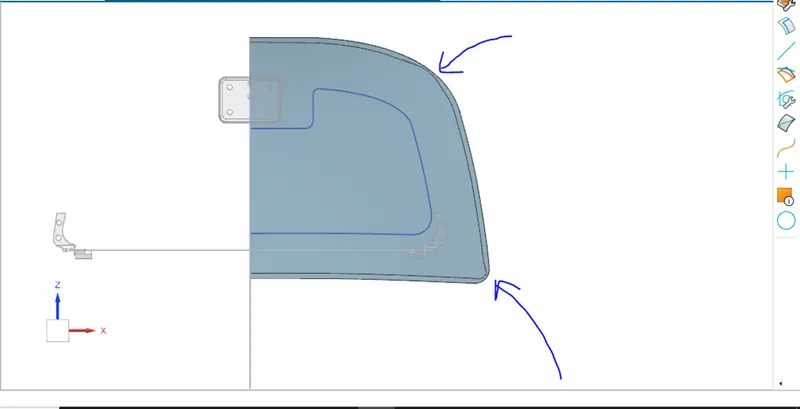
Now this outer panel is also mirrored on to the other side and is sewed. And finally it is provided the thickness of 0.75mm as shown in the figure below.
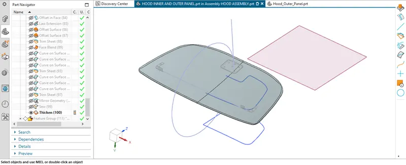
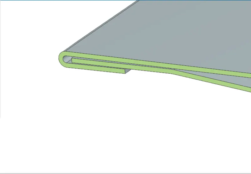
Hence our inner and outer panel design is fully completed.
Now we need to mount the hinges on to the hood inner panel in such a way that we can be able to find the striker trajectory also.
So here initially the hinges are placed roughly as shown in the figure below.
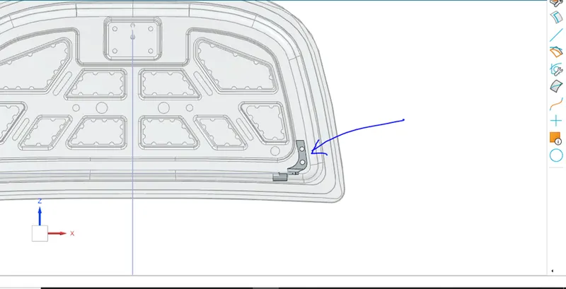
Then as we are going to place the hinge on to the inner panel, the place where the hinge is placed loose the strength and then to add the strength we need to give the reinforcement as shown in the figure below.
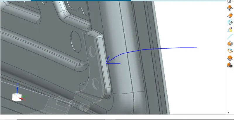
Reinforcement is nothing but the addition of the material base to provide strength to the component.
Now this reinforcement is provided with the blends and then whole geometry is mirrored to another side as shown in the figure below.
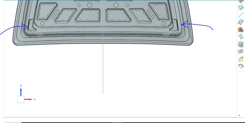
Now as the hinge is placed and the constraints are given to the hinge assembly we need to draw the trajectory of the striker following the path.
For this the center points on to the hinge axis are created and then the line is drawn parallel to the hinge axis and then from this center the circle is drawn to locate the position of the striker, latch as shown in the figure below.
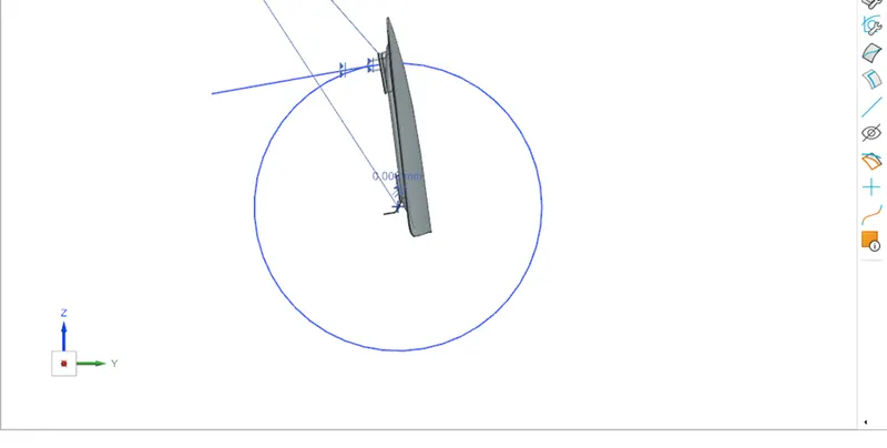
The position at which the striker fits the best place, there the striker is mounted using the coincident relation as shown in the figure below.
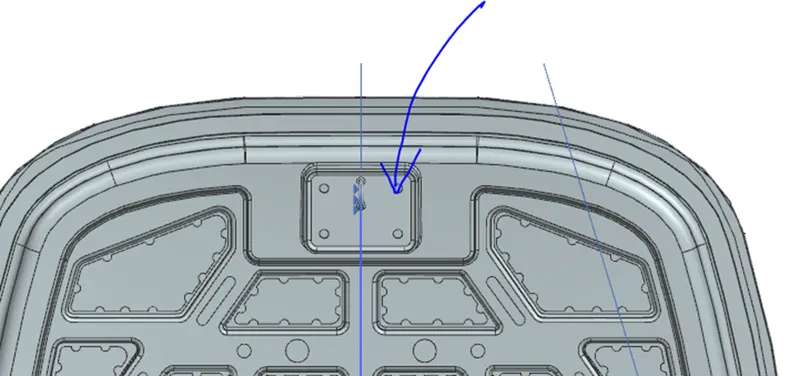
But now we need to create the emboss for the striker in the inner panel so here the striker back plate is extracted and then the law extension command is used to create the emboss. Finally it is trim and extend and we get the striker emboss ready.
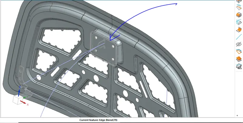
The striker emboss.
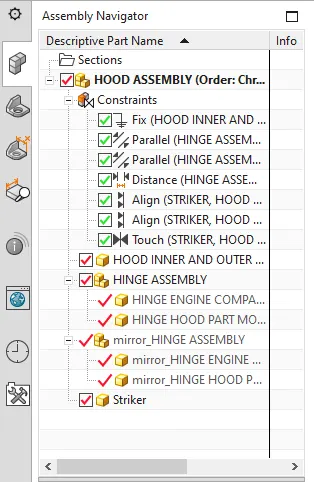
Finally the all the constraints are provided to the components and the whole design of the hood is ready.
Now if the frontal impact occurs the force will be dissipated in the following way as shown in the figure below.
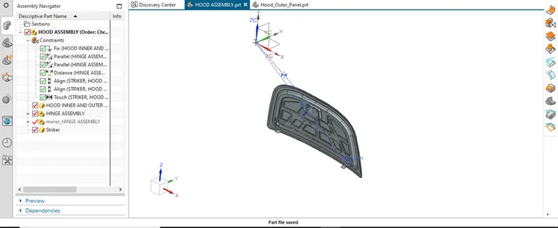
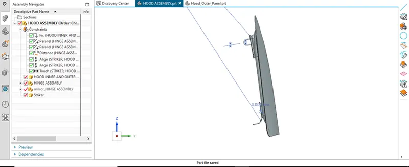
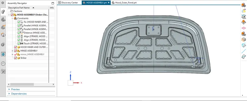
Hence the design of the hood is fully complete and our hood design challenge gets finish.
IMAGES :-