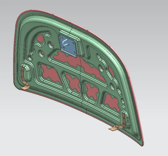
Hood design-Week 2
AIM:
To design a Hood of a Car based on Engineering inputs, Design considerations & Safety factors that satisfy the industry's manufacturing requirements and functional requirements using NX CAD.
INTRODUCTION:
The hood which is also known as the bonnet is the hinged cover over the engine of a car that allows access to the engine compartment.
The hood release system is common on most vehicles and usually consists of an interior hood latch handle, hood release cable, and hood latch assembly. The hood latch handle is usually located below the steering wheel, beside the driver seat, or set into the door frame.
In this project, we will be focused on designing the inner panel and outer panel of the hood and finally assembling them with the given hinge assembled part of the latch and sticker reinforcement.
Since we are initially dealing with sheet metal of infinitely small thickness, the hood is predominantly designed using Surface Modelling tools.
HOOD ASSEMBLY:
The Hood is basically a sheet metal assembly of various parts such as the outer panel, Inner panel, Latch & Striker, and Hinge. Finally, the hemming is done in order to roll the outer panel over the inner panel.
The inner panel provides strength while the outer panel functions as the metal cover. They both are held together by mastic seals.
The Latch and Stricker are primarily responsible for precise and flush car door closure and also for keeping the door securely closed. Subsequently, the sticker as the decisive counterpart for the Latch is a central element with enormous importance for the flawless function of the entire closure system.
The Hinge is a movable joint or mechanism on which the hood swings as it opens and closes while connecting the hood and the engine compartment.
DESIGN CONSTRAINTS TO BE FOLLOWED:
- Passenger Saftey
- Pedestrian Saftey
- Manufacturing Feasibility
- Positioning the striker along the trajectory of the center of the hinge axis
- Joining techniques of the inner and outer panel
Passenger Safety:
Whenever a frontal crash takes place in a car the first part which will get affected will be the hood. So, the hood must be designed in such a way that it should not come off from the body of the car and must absorb the energy as far as possible and divert the force towards the side panel of the car, so that the amount of force which is sent to the cabin is lesser since the force is lesser the passenger will experience less amount of force so, that passenger is achieved.

Hood inner panel plays a major role in dissipating the force away from the passengers. It is completely depending upon the emboss which is created in the inner panel. A typical emboss is shown below. The force will completely move along the direction shown above minimizing the force exerted towards the cabin.
Since the emboss has curved surfaces it will also absorb the energy transferred during the collision occurs.
PEDESTRIAN SAFETY:
Safety of the pedestrians needs to be considered during the design as per the NCAP Euro assessments.
Hood is of two types based on the side reference line. The side reference line is an imaginary line drawn from the ground at an angle of 45 degrees. If the line falls on the fender then the hood is an inlaid hood and if the line falls on the hood, then the hood is the wrap-around hood.
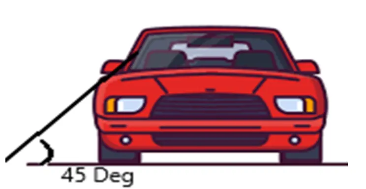
Child and adult impact areas on the hood are definitely by the wrap-around distance (WAD).
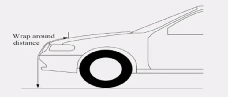
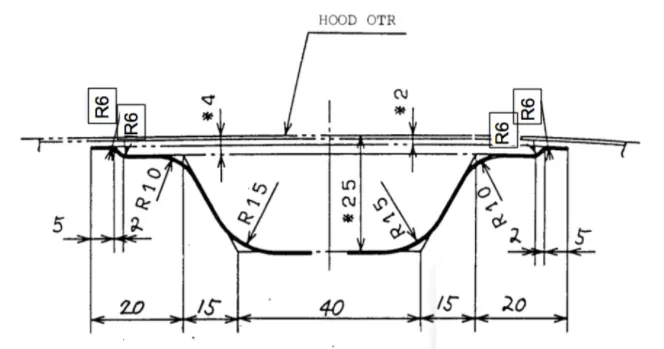
The area between the wrap around the distance of 1000 to 1500 mm is a child head impact zone and from 1500 to 2100 WAD is the adult head impact zone. Now since we know the zones where the pedestrians going to be hit, as a design engineers, we must make sure that they are experiencing the least force such that they were not getting any severe injury without compromising the strength of the hood so that passenger safety is also assured. For this reason, the inner panel is kept at 25mm from the outer panel, and creating the embosses is to provide the strength of the hood.
The Head impact area will typically look as shown in the image is defined based on the side reference line and the wrap-around distance.
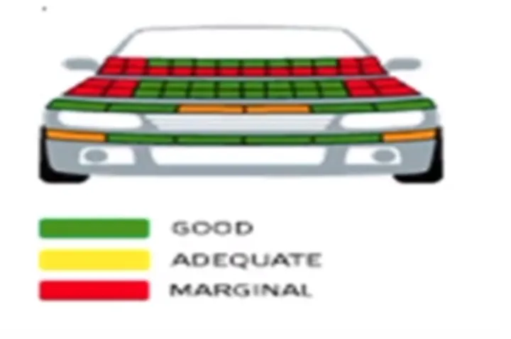
These zones will get a red, yellow, or green rating based on the Head Injury Criteria calculated using the expression.
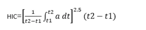
a = Acceleration of the head during impact (Measured in gravity)
t2-t1 = interval between the beginning and the end of the recording where the HIC value is maximum (Value can be a maximum of 15ms)
HIC<1000 region will get assigned green rating if HIC value is between 1000 to 1350 then the region will get yellow color and HIC value more than 1350 then region becomes red.
DESIGN INPUTS:
Hood thickness information:
- Outer panel Thickness = 0.75mm
- Inner panel Thickness = 0.75mm
- Reinforcement Thickness = 1.5mm
Master Sketch:
INNER PANEL DESIGN:
The Inner panel master section has been designed on the master sketch. The inner panel is the critical part of the hood that acts as a force redirecting medium during a frontal crash. Hence, it becomes very important to ensure that the inner panel is designed in such a way that the damage caused to the passenger as well as the pedestrian is minimum.
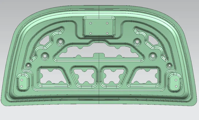
The inner panel consists of different contours known as Emboss and various cutouts made on the embossing which reduces the weight of the hood. It also consists of the mastic sealant extracted from the cutout edges.
The various commands and features that were used to design the inner panel are given as follows:
- Offset surface: This command is used to create a surface or a body by offsetting a set of faces.
- Offset Curve in the face: Offsets curve along with the faces on which they lie.
- Trim Sheet: Trims off a portion of a sheet body.
- Trim and Extend: Trims or extends a set of edges or faces to the intersection with another set of edges or faces.
- Extend Sheet: Extends a sheet body by distance or the intersection with another body
- Trim Body: This command is used to trim a portion of a body along a plane or a face
- Through Curves: Creates a body through multiple sections where the shape changes to pass through each section.
- Law Extension: Creates a law-controlled extension from the base sheet, dynamically or based on laws for distance and angle.
- Face Blend: Adds tangent blend faces between faces based on the radius specified.
- Edge Blend: Rounds sharp edges between faces based on the specified.
- Projected Curve: Project curve, edges, or points onto the faces or planes.
- Emboss: Modifies a body with faces made by projecting a section along a vector, with options for end cap location and shape.
- Curve on Surface: Creates a surface spline feature directly on a face.
- Mirror Geometry: Copies geometries and mirror them across a plane.
- Sew: Combine sheets bodies by sewing the common edges together, or combine solid bodies by sewing common faces.
- Thicken: Creates a sold body by adding thickness to a set of faces.
Embosses:
The embossed are projected sections from the inner panel surface that are created in order to redirect or dissipate the forces away from the center of the hood, towards the hinge to avoid passenger damage.
The embosses with varying depts (5mm, 6mm, 9.5mm) are provided on the hood for reinforcement and to add strength to the inner panel.
The following image shows the path of the force exerted due to collision in such a way the damage to the passengers is minimized.
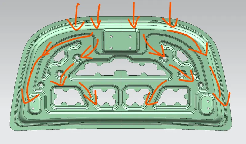
The arrows denote the impact force during the collision and the line of action of force traveling from the center of the center and towards the hinge.
Manufacturing Feasibility:
While designing a component a design engineer must make sure that the component can be produced by any means of manufacturing methods with the least amount of time, material, manpower, and power. So that we can reduce the overall cost of cars.
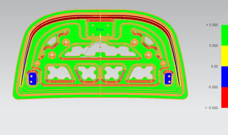
When the hood is considered it is manufactured by deep-drawing most of the time. Deep drawing is the process where a single sheet of metal is placed over a die which has the desired shape of the final output and the sheet is pressed against it with a tool/ For the tool to come out from the par usually pressing relief of 5 degrees and 9 degrees will be provided during modeling itself.
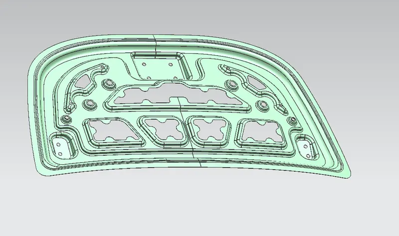
In NX draft analysis can be done after modeling so that we can verify whether the product is manufactured by pressing or not. One side of the surface is highlighted by green and another side with red color means that the model can be manufactured. The result of the draft analysis is shown in the figure below.
Mastic Points:
The Mastic sealant or the Mastic point is an elastic compound that behaves like rubber. Tha Mastic points are defined on the hood inner pane; where the hood can easily deform.
They help the hood outer panel to come back to its original shape after it gets deformed. The mastic has an influence area of 80mm. They also play a major role in the reducing NVH (Noise, Vibration, Hardness) of the car.
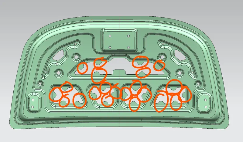
The red circles indicate the mastic positions.
LATCH & STRICKER AND HINGE ASSEMBLY:
This is a critical stage in Hood design as it plays an important role in the opening and closing of the Hood.
The positioning is done as shown below concerning the Hinge axis so that the circle is passing through the center of the sticker with the Hinge axis as its correct position and thus enables it to close with that latch.
The sticker needs to be placed on the trajectory of the center of the point of the hinge axis to ensure that it fits perfectly on the latch, if not locking will not be smooth and affects the comfort, and also will create NVH Problems.
The striker is aligned using the following steps
- Drawing the line along the axis of the hinge
- Creating the point on the midpoint of the line
- Drawing the circle from the midpoint of the line to the latch where the striker will be mounted.
- Drawing the line from the center point to the midpoint of the striker end.
- Aligning the line's endpoint and the midpoint of the stirker of the circle.
- The angle needs to align so that the angle of the striker is perpendicular to the line drawn from the mid point of the axis line of the mid point of the striker.
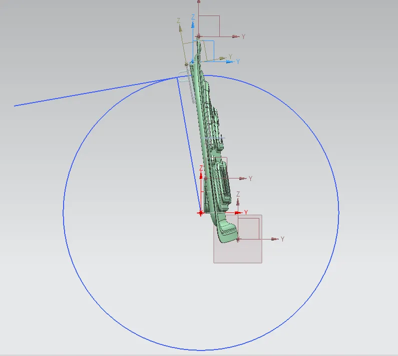
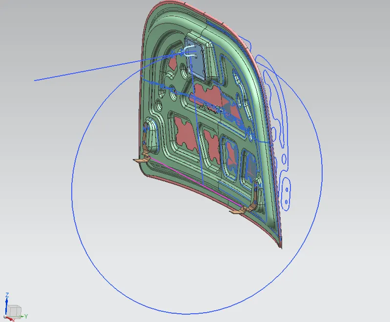
Now the striker will move along the trajectory of the circle drawn.
HEMMING:
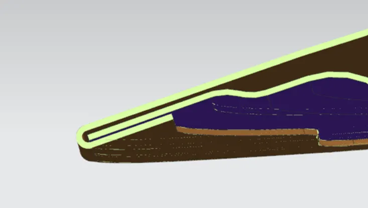
Hemming is the process of joining both the outer and inner panels together. The hemming process roles and wraps the hood outer panel around the inner panel holding its tightly together. The following image shows the result post hemming process.
CONCLUSION:
Thus the Hood design is considering passenger and pedestrian safety as per the master section and Striker is also places in the path of the trajectory of the hinge axis.