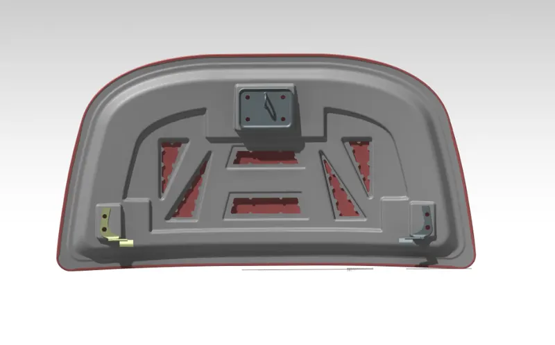
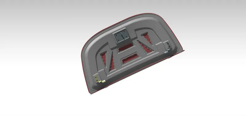
Hood design-Week 2
AIM:
To design hood outer panel, inner panel, necessary reinforcements and the embosses by considering the master section and design parameters.
INTRODUCTION:
In British terminology, hood refers to a fabric cover over the passenger compartment of the car (known as the 'roof' or 'top' in the US). In many motor vehicles built in the 1930s and 1940s, the resemblance to an actual hood or bonnet is clear when open and viewed head-on; in modern vehicles it continues to serve the same purpose but no longer resembles a head covering.
On front-engined cars, the hood may be hinged at either the front or the rear edge, or in earlier models (e.g. the Ford model T) it may be split into two sections, one each side, each hinged along the centre line. A further variant combines the bonnet and wheelarches into one section and allows the entire front bodywork to tilt forwards around a pivot near the front of the vehicle (e.g. that of the Triumph Herald ).
Hoods are typically made out of the same material as the rest of the body work. This may include steel, aluminium, fiberglass or carbon fiber. However, some aftermarket companies produce replacements for steel hoods in fiberglass or carbon fiber to make the vehicle lighter.
DESIGN CONSIDERATION FOR HOOD DESIGN:
- PEDESTRIAN SAFETY:
Vehicle safety factors should simultaneously consider occupant and pedestrian safety, given that pedestrians are the third largest category of traffic fatalities. Most pedestrian deaths occur due to traumatic brain injury, resulting from the hard impact of the human head against the vehicle's stiff hood or windshield. Therefore, how to design a pedestrian-friendly vehicle and propose a new hood structure is a matter of urgency for minimising pedestrian head injuries. In assessing the friendliness of vehicle hoods, this study adopts the EEVC/WG17 regulations on headforms for hood tests. The finite element method is used to simulate the impact between the vehicle's hood and the headform impactor. The software used in simulation is LS-DYNA. The results predicted by the headform-hood tests show that the hood structure with aluminium-reinforced polycarbonate material provides enough absorption capability to protect pedestrians from the impacts of accidents. It is also stiff enough to keep pedestrians' heads away from the inner parts of the engine cavity. The analysis models and sandwich materials proposed herein contribute to efforts to design vehicle hood structures and pave the way for developing pedestrian protection technologies.
- HEAD CLEARANCE ZONE:
Head clearance zone is the clearance such thatwhen the hood is in fully open condition it should not hurt the head of the person who is standing next to the hood. This is controlled by the opening angle of the hood. The opening angle of the hood is decided for the region of the car is manufactured. Some region may have people with average height of 5.5 ft and another region may have people with average height of 6 ft. So, deciding the right opening angle for the hood is an important criteria.
- CONSIDERATION OF NOISE, VIBRATION AND HARSHNESS (NVH):
NVH plays important role in car design. It should be designed in such a way that the noise produced by the car should be minimized. It can be acheived by using stiffners pads and mastic seals. stiffner pads and mastic seals are added in between inner and outer panel of the hood.
GIVEN DATA.
MASTER SECTION:
HEMMING DATA:
RELIEF SECTION:
PROCEDURE:
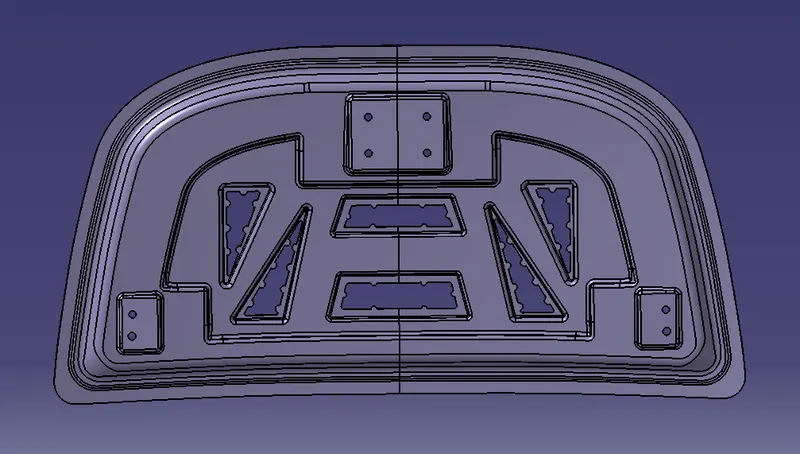
- Design of Hood Inner Panel:
Inner panel is a major part which acts as a support for the outer panel. It consist of embosses which helps in distribution of forces during impact. The thickness of the inner panel is 0.75 mm as per the given data. The inner panel is created using the master section shown in the given data
- Door Hood Outer Panel:
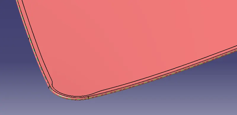
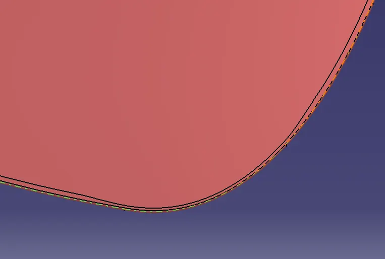
Outer panel is a skin of inner panel which gives a luxurious look to the car, The hamming region is created to the class A surface, Through which the outer panel is joined to the inner panel. The relief has given in the corners. Relief are provided on the surface to avoid springback situations. The thickness is given as per the data i.e, 0.75mm.
- Creation of Hood Outer Panel is as Follows:
The hood outer panel is created with the help of reference surface given ffor the creation of hood outer panel.
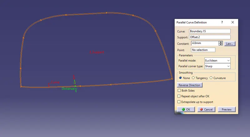
The offset of the given surface is made with a distance of 3.15mm below of it as shown in the below figure.
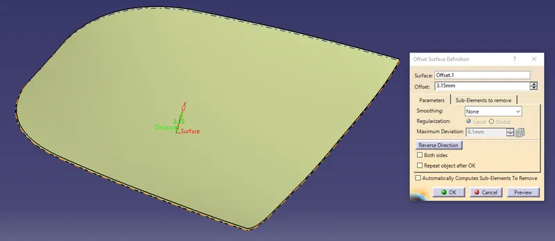
From the offset component we can able to create a parallel cure on the given surface and made a sweep operation for 8 degree angle with the draft direction. which follows the draft analysis which is helpful for the manufacturing process.
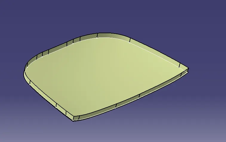
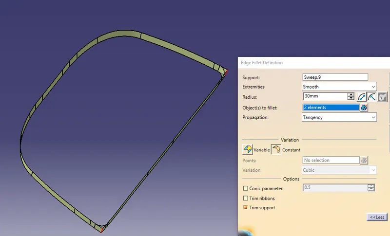
The sharp corners can be removed with the help of applying the edge fillet to the sharp corners with a maximum of 30 mm diameter.
After applyinhg the sharp corners to the hood outer panel component finally we need to cut the element for the relief angle projection which is perfectly applicable for the hemming operation and can be made perfect shape of it.
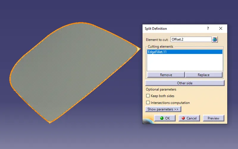
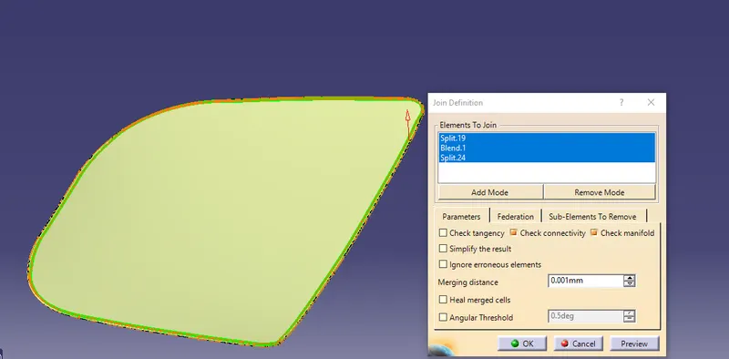
The final component can be getting with the joining of all the operation we have made in the hood outer panel component which is shown in the below figure.
- Latch placement:
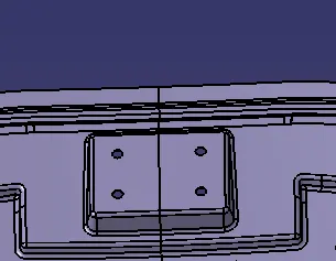
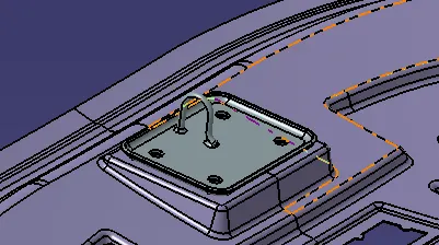
Whenever we add a weight to the material it looses its strenght on that area locally. To componsate that loose, reienforcements are added.
- Embosses:
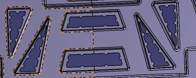
Embosses will add a strengh to the material. These will help in the distributing of forces during the impact rather then directing it towards the passengers sitting inside of the car.
- Stiffner pads and Mastic seals:
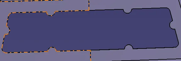
These both will help in minimizing the NVH in the vehicle during motion. basically mastic seals are a rubber kind of material placed in between the inner panel and the outer panel of the hood, Which also helps in holding both together. Every mastic seals have a tendency to improve the strength locally by 80 mm diameter.
- Hinge Assembly placement:
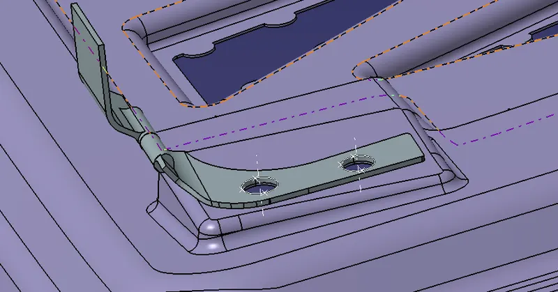
A hinge including a first hinge half rotatably connected to a second hinge half is described. A support mechanism selectively supports the first hinge half at one or more rotated positions relative to the second hinge half. The support mechanism includes a support which is selectively biased toward a support position in which the support is capable of supporting the first hinge half at a rotated position relative to the second hinge half. The support can further be selectively biased into a disengaged position in which the support is not capable of supporting the first hinge half relative to the second hinge half. With the support in a disengaged position, the first hinge half is freely pivotable relative to the second hinge half. An automatic reset mechanism may be utilized in connection with the hinge to reposition the support from the disengaged position to the support position as the hinge approaches a predefined position.
- Hemming:
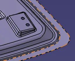
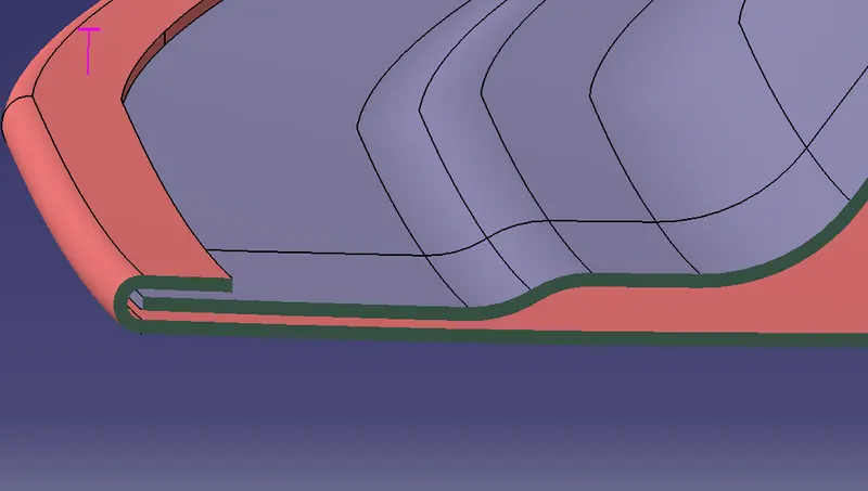
Hemming is the processes where the outer panel is joined with the inner panel by adding extra material on the outer panel and made to wrap around the inner panel. The wrapping is done using the running ball rolls throught the end of the sheet.
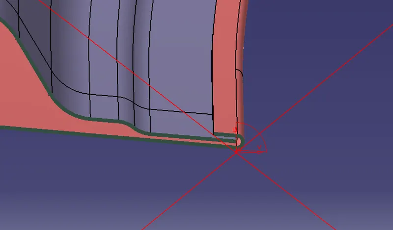
RELIEF AT THE CORNERS:
- Position striker with trajectory method for placing the Latch and Hinge Assembly:
Two parts are used to test the developed trajectory connection algorithm.
- The radiator upper panel (front view);
- The radiator upper panel ( side view);
- The hood inner ( front view);
- The hood inner ( side view);
- For the proper opening and closing of the hood, the striker should be positioned at a correct position.
- The striker should be perpendicular to the trajectory of the hood.
- The trajectory of the hood is denoted as a circle which drawn by using the centre of a straight line which passes through both the hinge axis at their respective position.
Final Images of Hood aAembly with all the Engineering Features on it as shown in the Below Figures.
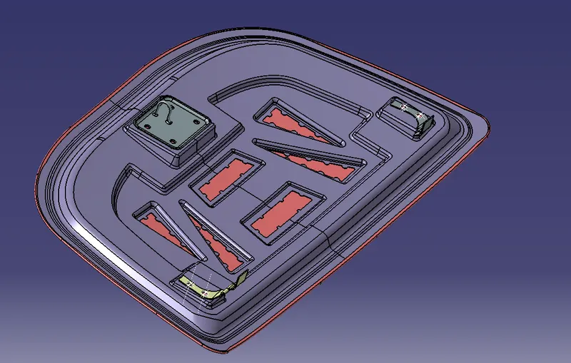
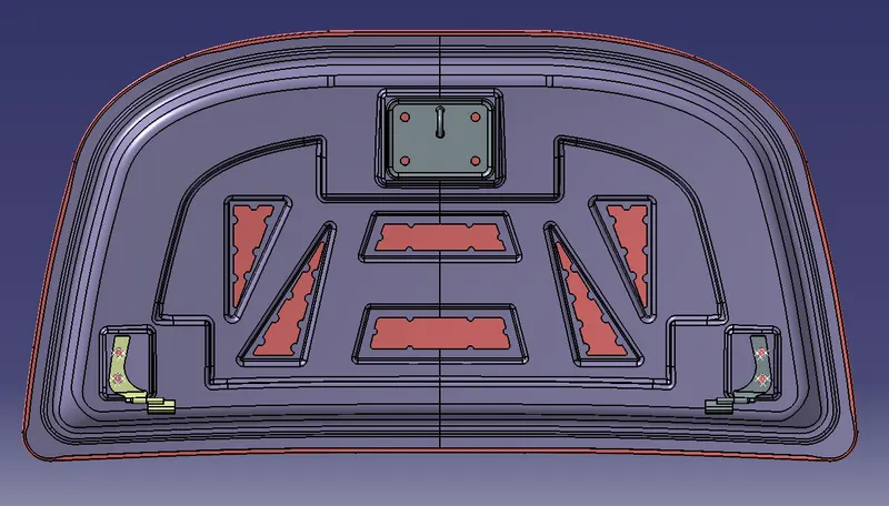
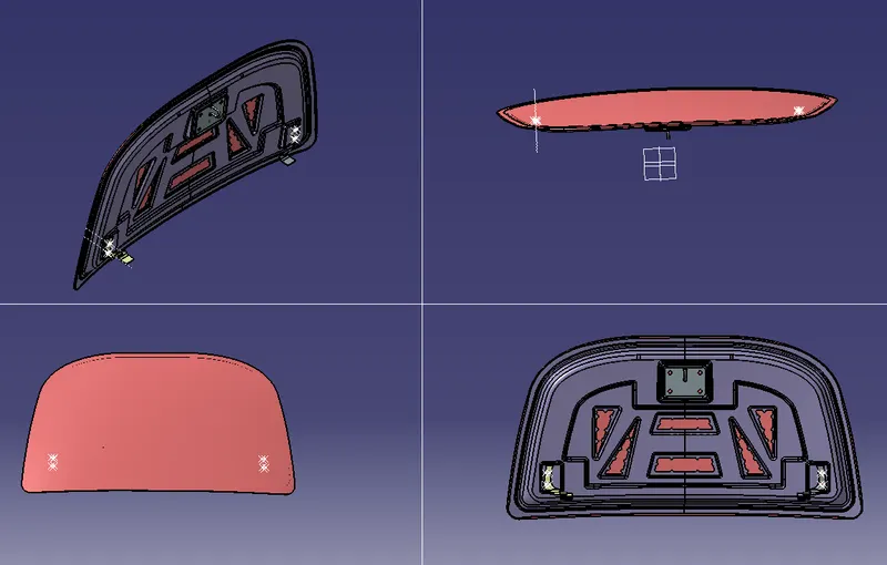
Rendering Images of The Hood Assembly Panel is shown in the below figures:
- Rendering a part is the last step for a final product. If you want to make a real look for your part, you should use this feature of CATIA.
- The rendering time of a part or assembly is different depending to the settings and quality do you choose.
- For example, if you want to have a high-resolution render of your part, the time will be longer, and if you want a fast rendering you should use low resolution and medium or low quality.
- You can choose the source light, the number of sources or the type. Also, you can change the background color, or image by uploading a new background image.
- For example, if you want to see how looks your part on a table, you can take a photo of the table, upload this in your PC and put it in the background.
- Look for the light source and edit the light direction to have same shadows. This tip, works very well when you want to create a catalog.
- For a real look, you can change the view of your part from parallel to perspective.