Hood design-Week 2
The objective of this assignment is to design the Hood Inner panel, Outer panel from the outer panel surface or skin and correctly positioning the Hinges and the Latch and necessary Reinforcements to mount them.
CAR HOOD:
The hood is a BIW component which consists of Inner panel and outer panel. The inner panel provides strength whereas the outer panel functions as a metal cover.
The hood dissipates the energy from the car body to the outside rather than inside.
A car hood also referred as Bonnet in some other countries is the hinged cover that rests over the engine of a front-engine vehicle. Hoods can be opened to allow access to the engine compartment for maintenance and repair.
It plays an important role in frontal crash analysis and pedastrian safety.

The car hood is designed by taking lot of things into considerations. The Inner panel of the car hood is the most critical component to design as we have to consider many design criterias, and the Outer panel is designed in order to resist the aerodynamic drag force as well as to add better looks and style to the car.
PARTS OF HOOD ASSEMBLY:
1. Hood Outer Panel
2. Hood Inner Panel
3. Hinge Assembly
4. Striker
1. Hood Outer Panel- This component acts as the metal cover and gives good finish and better looks to the car.
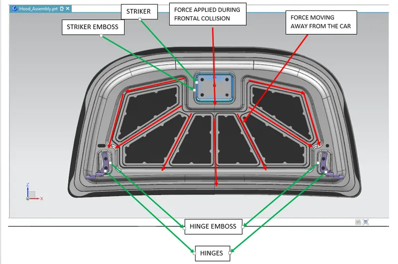
2. Hood Inner Panel- This component is the main part where all the embosses are present.
3. Hinge Assembly- It consists of 2 parts, One is Engine compartment part and the other is Hood model part. The hinges are basically used to give oscillatory motion to the hoods so that it can open and close.
4. Striker- This is the part which gives the secondary locking to the hood. The striker is present in order to get locked in the latch so that the hood does not open easily and during driving also which prevents from noise and vibration.
DESIGN CRITERIA:
1. HOOD HEAD ZONE FOR LOCK STRIKER (OPENING ANGLE):
The opening of the hood varies from region to region and is decided by the average of a person in that particular region.
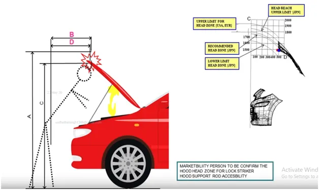
The opening of the hood is controlled by the Support rod or Gas stay. So by definig the length of the support rod or gas stay and the location we can vary the distance of the hood opening.
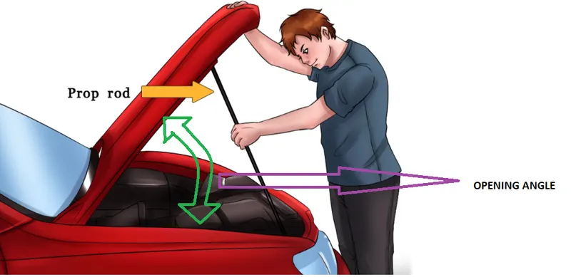
The important criteria is
1. Whenever we open the hood there must be a clearance between the tip point of the hood and the striker.
2. Whenever we release the primary latch from the car we must have a distance of 10 to 15 mm to put our fingers and to open the secondary latch to open the hood and this distance is kept common for all regions.
2. REINFORCEMENTS:
Inside the inner panel of the hood where we need to place the hinges and the striker-latch we need to provide slots. By providing slots we loose material in that area and as a result we loose strength in that particular area too.
So in order to compensate the loss of strength we need to add Reinforcements.
Reinforcements are the additional weight on material that are given in order to compensate the loss of strength. They are intentionally given to improve the strength locally.
Reinforcement added for the striker can be called as Striker Reinforcement and for Hinges it can also be called as Hinge Reinforcement.
Reinforcement thickness is defined by the amount of loss that occurs and this analysis is done by the CAE team or from the carry-over study.
3. WRAP AROUND DISTANCE (WAD):
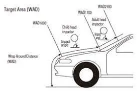
When a car crashes on to a pedestrian the whole human body tends to wrap around like the front shape of the car and the head impacts on the hood or the windscreen.+
The distance from ground to the position where the head impacts on the hood of the car is called as the Wrap Around Distance (WAD). It is measured longitudinally from the centre of the vehicle from the ground.
The severity of the injury caused by the frontal crash depends upon the type and shape of the vehicle, speed of the vehicle and movement of the pedestrian relative to the vehicle. In addition to these parameters the WAD plays an important role in the safety measurement of the pedestrian.
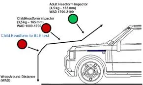
During the crash analysis based on the WAD two test areas are created namely Child Head Impact Zone and Adult Head Impact Zone.
The child head impact zone is between 1000mm to 1700mm WAD.
The adult head impact zone is between 1700mm to 2100mm WAD.
EURO-NCAP ASSESSMENT:
The EUROPEAN NEW CAR ASSESSMENT PROGRAMME is a safety test that is conducted on new cars to rate the cars based on their safety.
This test plays important role in designing the hood of the car to get better ratings in the frontal crash analysis.
The ratings are based on the impact zones of the pedestrian and their effect.
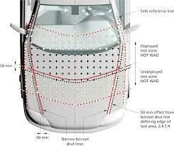
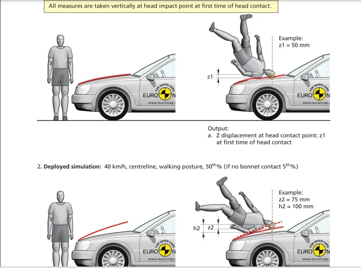
This test is carried out by offsetting the Hood outer panel by 90mm inside to check the impact of head after collision because by offsetting we will get the interference with the engine compartments.
This intensity of the interference gives us the regions that are RED, YELLOW and GREEN. With RED standing for more interference and GREEN for less interference.
More will be interference with the engine compartments more will be the impact on the head so if there are more RED regions then the car will be getting less rating, So we must design in such a way that there would less RED regions and more GREEN regions to get more ratings.
In order to reduce the RED zones we have remove materials in that area and make that area softer so that after collision there would be less impact on the heads of the pedestrian and damage on their heads would be reduced.
4. MASTIC SEALANTS:
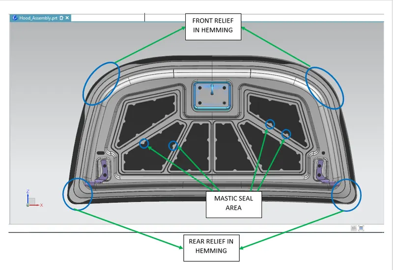
Mastic sealants are used in between Hood outer panel and inner panel. It is used for Noise Vibration and Hardness (NVH).
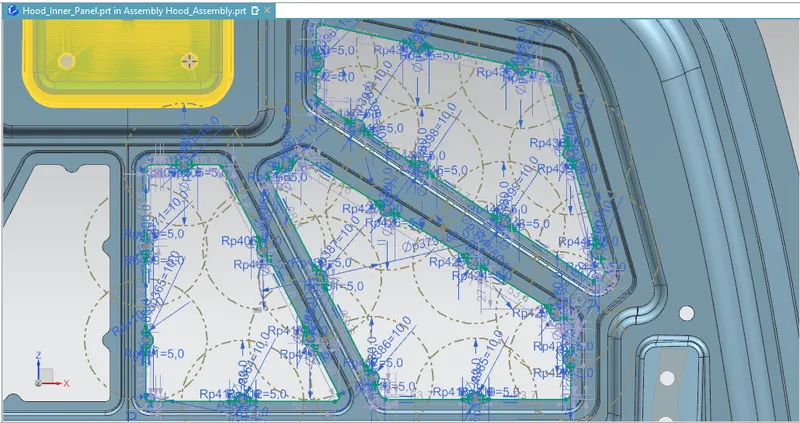
Every mastic sealants have the tendency to improve the strength locally around 80mm diameter. So the mastic sealants are placed in such a way that most of the hood regions are covered.
It is introduced as a paste between the outer panel and the inner panel and when it goes into the hot bath inside the furnace it hardens and it joins the outer sheet metal and inner sheet metal.
The gap between the inner panel and the outer panel is 5mm and this gap is to be filled by the mastic sealants.
6. LATCH TRAJECTORY:
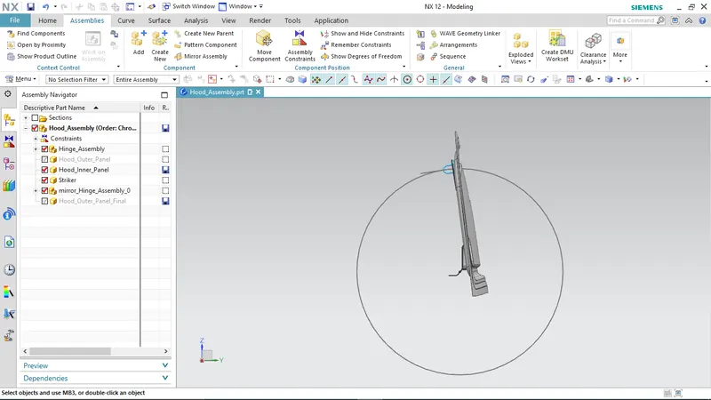
The most important criteria is to place the striker so that the latch mechanism happens correctly and for this we have define the striker position and find out its trajectory .
To position the striker we have to
1. Fix the hinges at their respective position.
2. After placing both the hinges the hinges will have a common axis.
3. We have to draw 2 points at the both the centres of the hinge axis and create a line passing through this point which will be line passing through their axis.
4. We have to find the centre point of the striker.
5. The distance between the centre point of hinge axis and the striker axis will be the radius of a circle and taking the centre of the hinge axis we need to draw the circle.
6. This circle will be the trajectory of the hood opening and closing.
7. The striker should be placed such that the striker is exactly perpendicular to the trajectory circle.
By following the above method we need to position our striker so that there will be a perfect latch mechanism.
6. HEMMING:
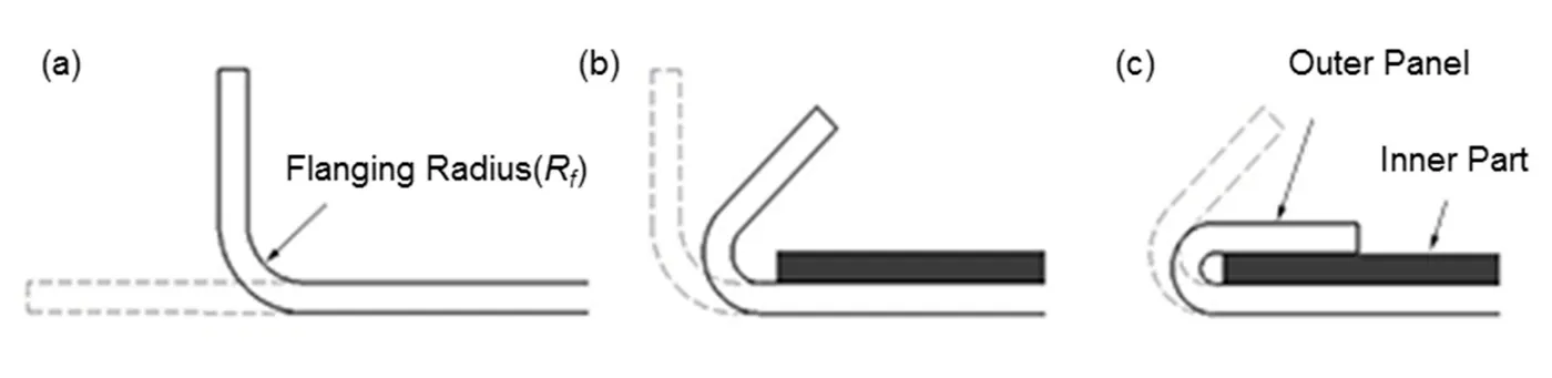
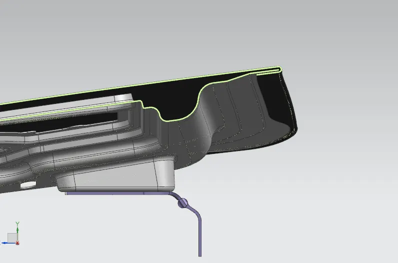
Hemming is a process to join two sheet metals by folding one sheet metal over the other.
Hems are folds to the edge of a part to create a rounded safe edge. Hems may be open, flat, or tear-dropped and tolerances depend on the hem's radius, material thickness and features near hem.
Hems are created by bending a flange of a part back on itself. This increases the strngth of the hemmed edge and also gets rid of any sharp edges.
Hemming is done by the rollers. These rollers are placed at the edges of the part and they start rolling over them which bends the sheet and creates hem, This process is called Hemming.
DESIGN PROCEDURE
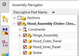
At first we need to create a Assembly file and call all the parts required.
1. Hood Outer Panel
2. Hinge Assembly
3. Striker
Create a new part as Hood Inner Panel and Now by taking the the outer skin we have to offset the parent surface in order to create working surface for our Inner panel.
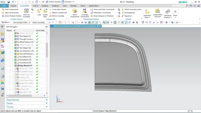
Now we need to work inside our new part i.e Hood Inner panel to create it.
At first as we need to create different flanges as per the master section provided.
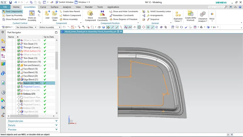
Next we have to create an Emboss and provide space for striker and hinge embosses.
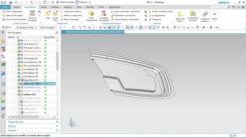
Now we need to fix our hinge position and create emboss.
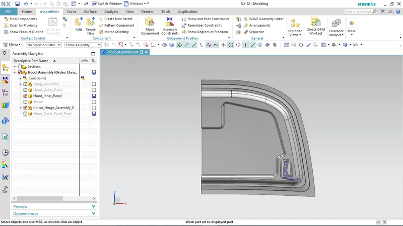
Now we have to mirror our entire hinge assembly and follow the above steps for Latch Trajectory and striker positioning.
Now in order to get the best rating in the EURO-NCAP ASSESSMENT we need to remove material from the inner panel to make it softer so that there will be more YELLOW and GREEN regions and less RED region so that there will be less impact on the head of the pedestrian during collision.
The materials should be removed in such a way that during frontal collision the force should move away from the car.
As during frontal collision the force tends to move towards the car or the windscreen that is the same direction in which the force gets applied so the aim of the design should be to disspate the forces away from the car.
By doing so the force going inside the car cabin reduces drastically.
And also we need to provide embosses to do so and also keep in our mind to provide spaces for the MASTIC SEALANTS.
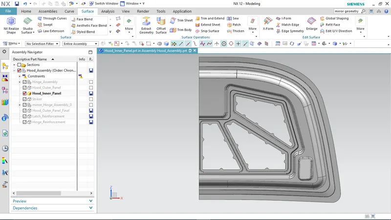
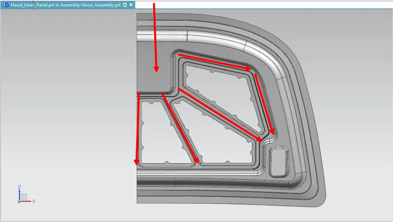
MASTIC AREA
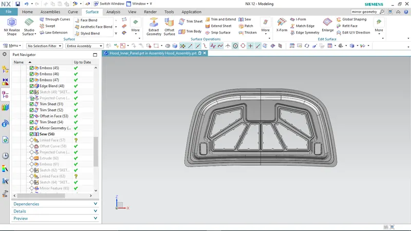
Now as we have completed the half of Inner panel of the hood we can mirror the geometry and sew in-order to make a single part
After this we can make the emboss for the Striker
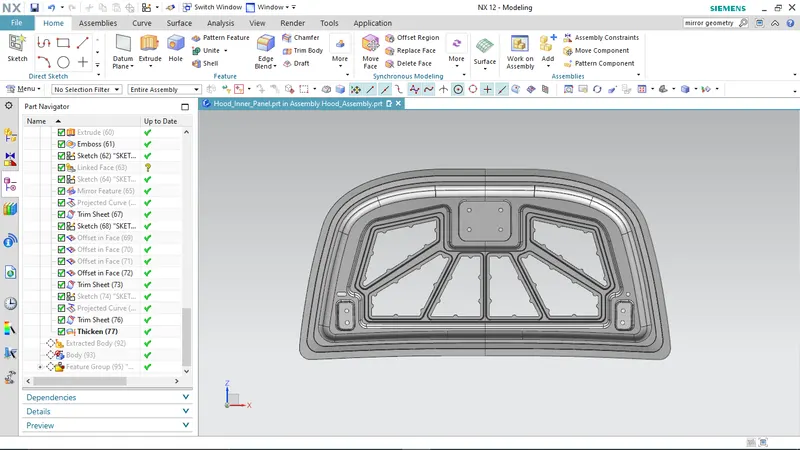
Now as the whole part is completed we can finally thicken the Inner panel as per the given data i.e 0.75mm.
As we have removed material inside the inner panel to make it softer to get better ratings at EURO-NCAP, the strength of the panel also gets reduced so we have to give reinforcements in order to compensate the loss of strength.
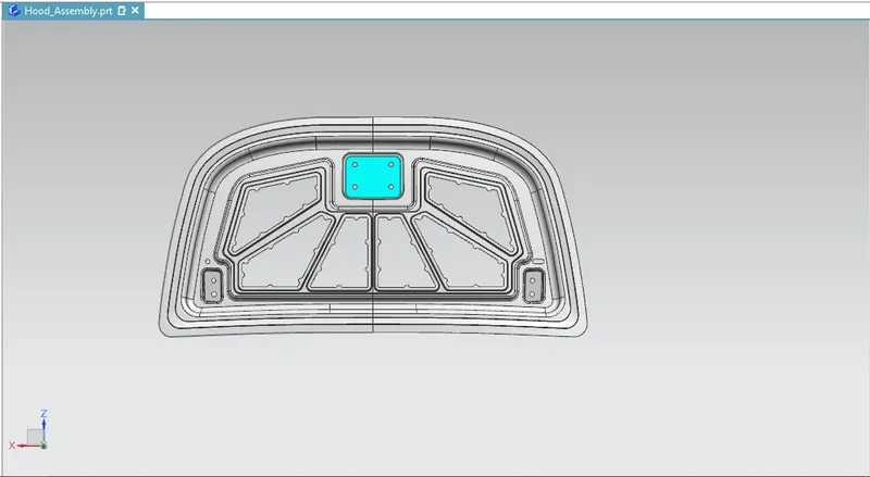
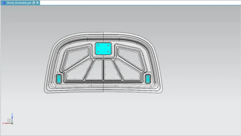
In order to compensate the loss we have given reinforcements at hinges and striker location.
STRIKER REINFORCEMENT:
HINGE REINFORCEMENT:
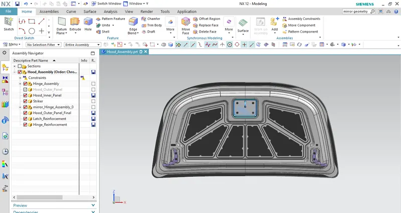
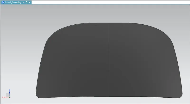
After completing all the components of the Inner panel we can sketch the Outer Panel and do the Hemming operation on it and make it other part by Extracting the Geometry.
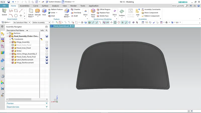
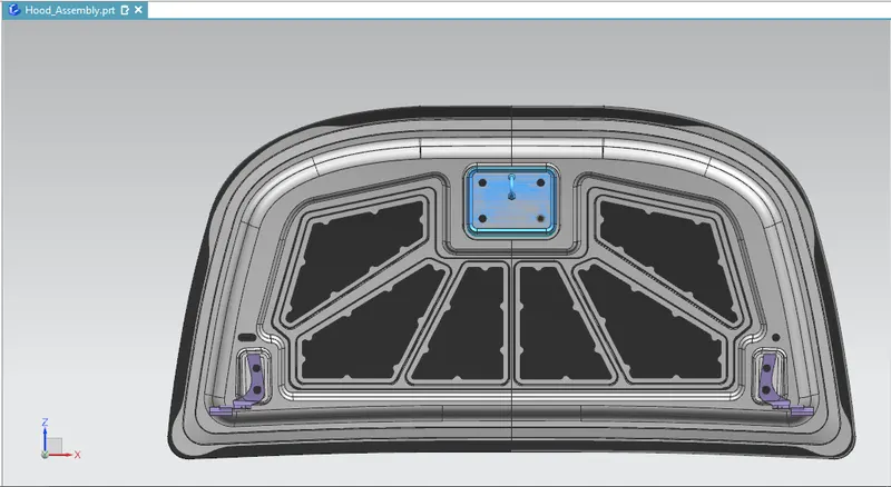
FINAL PART
HEMMING
DEEP DRAWING:
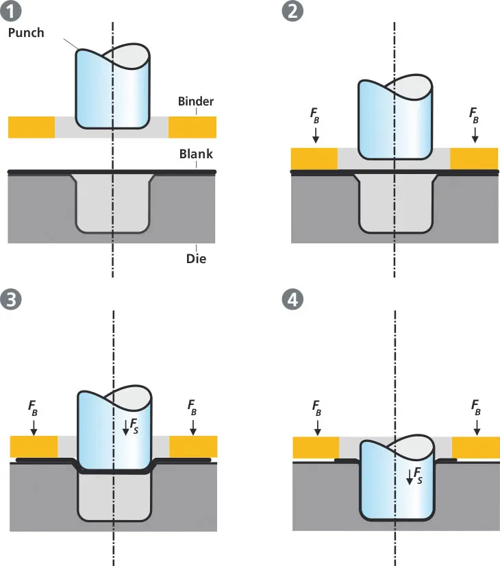
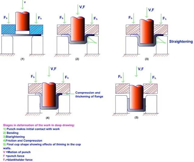
Deep drawing is a Sheet Metal Forming process in which a sheet metal blank is radially drawn into a forming die by the mechanical action of a punch. It is thus a shape transformation process with material retention. The process is considered "deep" drawing when the depth of the drawn part exceeds its diameter. This is achieved by redrawing the part through a series of dies. The flange region (sheet metal in the die shoulder area) experiences a radial drawing stress and a tangential compressive stress due to the material retention property. These compressive stresses result in flange wrinkles (wrinkles of the first order). Wrinkles can be prevented by using a blank holder, the function of which is to facilitate controlled material flow into the die radius.
The total drawing load consists of the ideal forming load and an additional component to compensate for friction in the contacting areas of the flange region and bending forces as well as unbending forces at the die radius. The forming load is transferred from the punch radius through the drawn part wall into the deformation region (sheet metal flange). In the drawn part wall, which is in contact with the punch, the hoop strain is zero whereby the plane strain condition is reached. In reality, mostly the strain condition is only approximately plane. Due to tensile forces acting in the part wall, wall thinning is prominent and results in an uneven part wall thickness, such that the part wall thickness is lowest at the point where the part wall loses contact with the punch, i.e., at the punch radius.
The thinnest part thickness determines the maximum stress that can be transferred to the deformation zone. Due to material volume constancy, the flange thickens and results in blank holder contact at the outer boundary rather than on the entire surface. The maximum stress that can be safely transferred from the punch to the blank sets a limit on the maximum blank size (initial blank diameter in the case of rotationally symmetrical blanks). An indicator of material formability is the limiting drawing ratio (LDR), defined as the ratio of the maximum blank diameter that can be safely drawn into a cup without flange to the punch diameter. Determination of the LDR for complex components is difficult and hence the part is inspected for critical areas for which an approximation is possible. During severe deep drawing the material work hardens and it may be necessary to anneal the parts in controlled atmosphere ovens to restore the original elasticity of the material.