Hood design-Week 2
Introduction
The hood or bonnet is the hinged cover over the engine of motor vehicles. Hoods can open to allow access to the engine compartment for maintenance and repair. Hoods are typically made out of the same material as the rest of the body work. This may include steel, aluminum, fiberglass or carbon fiber. However, some aftermarket companies produce replacements for steel hoods in fiberglass or carbon fiber to make the vehicle lighter.
The car hood consists of inner panel and outer panel. The inner panel provides strength and outer panel is just an aesthetic surface. Hood also gives good looks and helps design car aerodynamically stable.
The hood release system is common on most vehicles and usually consists of an interior hood latch handle, hood release cable and hood latch assembly. The hood release has a small lever, which is usually mounted under the dash. It is connected to the hood latch by a cable. The hood latch has a safety feature, which requires a second latch to be released before the hood is released. This is to prevent accidental opening while driving.
In Japan and Europe, regulations have come into effect that places a limit on the severity of pedestrian head injury when struck by a motor vehicle. This is leading to more advanced hood designs.
Hood design
This process involves following stages
- Development of hood inner panel according to the given master section
- Emboss creation in hood inner panel
- Placement of hinge assembly
- Placement of striker
- Hemming and Corner relief
- Mastic sealant
Development of hood inner panel according to the given master section
Since the given model is symmetric about Y-axis, we can trim the sheet about Y-axis. Offset outer panel surface to given dimensions to get the model as per given master section.
Emboss creation in hood inner panel
Embosses are the projections made on sheet metal using deep drawing techniques. This operation is carried out for the purpose of stiffening flat surface. The major function of embossing is to dissipate the force acting on the hood during collision of the car towards the hinges as early as possible. This help to reduce the impact on the passenger sitting inside the vehicle. In NX 12 emboss is created in following way.
- Sketch the outer boundary of emboss on suitable plane. Project the sketch on to the inner panel surface using ‘Project Curve’ command under ‘Curve’ toolbar.
- Under surface commands, go to combine and select emboss. Depth of emboss should be selected such that there exists at least 5mm space between inner panel and outer panel. Before final click ensure that under ‘End Cap’ option ‘Embossed faces’ is selected.
- After embossed surface is created, create the ‘Cutouts’ such that crash forces will be dissipated towards the hinge side.
- Create fillets of 2mm radius using ‘Blend’ command on all embossed edges.
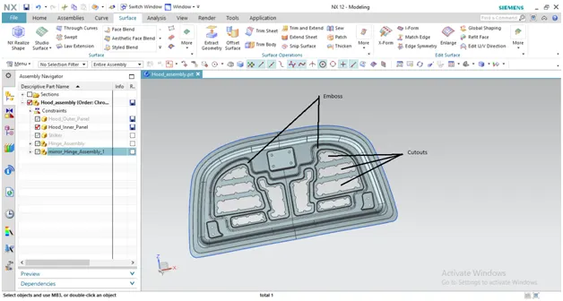
- Finally, use the mirror geometry command to get complete inner panel. Use 'Examine geometry' command to check the continuity between mirrored objects.
Placement of hinge assembly
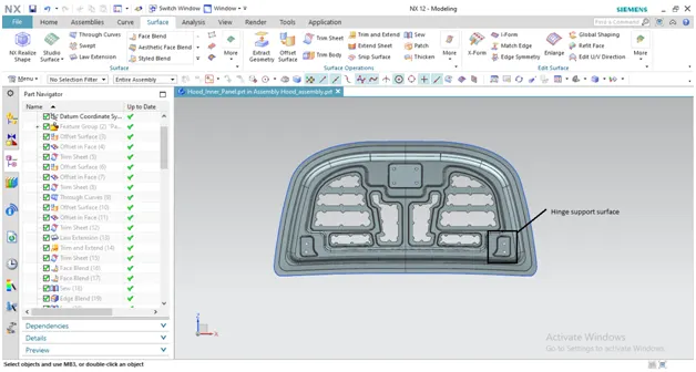
In car hood, hinges help in up and down movement of the bonnet doors. Hinge assembly must be placed on a flat surface on the inner panel. But the hood inner panel is a curvy surface. In NX 12, support surface for hinge assembly is created in following way
- Create a ‘Datum plane’, which is almost parallel to the hood inner panel.
- Sketch the desirable geometry on a suitable plane to create hinge support surface. Project the sketch on to the hood inner panel.
- Using ‘Emboss’ command, to create embosses up to the datum plane. Ensure that, under ‘End cap’ option, ‘Datum plane’ is selected.
- Create fillets of 2mm radius using ‘Blend’ command on all embossed edges.
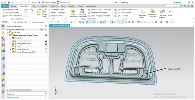
- Under ‘Assembly’ tool bar, use ‘Assembly constraints’ to create constrain the hinge assembly.
- Use ‘Mirror geometry’ command to get same hinge assembly on the other edge of inner panel. Before final click, ensure that ‘Associativity’ is checked in.
- Creation of holes: Select ‘Wave geometry linker’ command under ‘Assembly’ toolbar. Select the ‘Type’ as ‘Composite Curve’. Select the outer periphery of the hinge holes. Trim the sheet using these curves to get holes.
Placement of striker
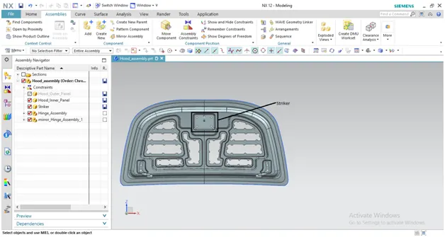
Striker supports locking mechanism in a hood assembly. Striker must be placed on a flat surface on the inner panel. But the hood inner panel is a curvy surface. In NX 12, support surface for striker is created in following way
- Draw a line connecting the arc center of hinge assembly. Sketch a circle in YZ plane, by selecting the middle point of the line. The periphery of the circle must pass through the striker placing surface.
- Draw a line connecting the centre of the circle and the periphery of the circle. Draw another line tangent to the circle as shown below.
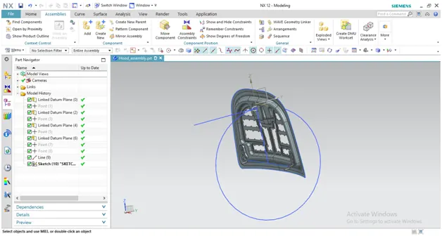
- Set the datum coordinate system on striker. Draw a line perpendicular to the striker surface.
- Use ‘Assembly constraints’ commands to align these two lines. This will constrain the motion of the striker
- Use ‘Wave geometry linker’ command (Ensure ‘Face’ is checked in ‘Type’ option) to get the back surface of the striker. Extend the periphery of extracted surface to 5mm. Create emboss by setting depth up to extracted surface (Ensure that ‘Plane of section’ is selected under ‘End cap’ option).
- Creation of holes: Select ‘Wave geometry linker’ command under ‘Assembly’ toolbar. Select the ‘Type’ as ‘Composite Curve’. Select the outer periphery of the striker holes. Trim the sheet using these curves to get holes.
Hemming and corner relief in outer panel
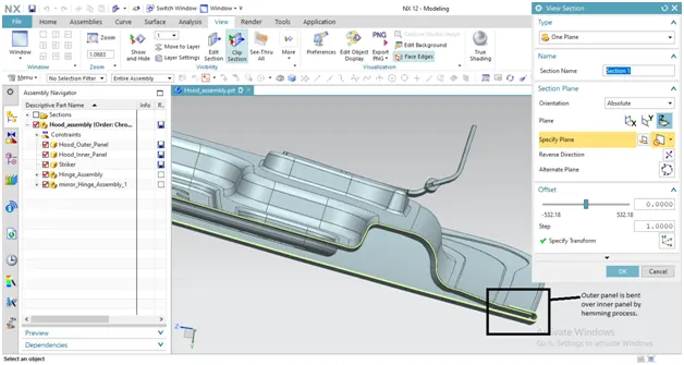
- The outer panel and inner panel can’t joined by welding process. If we did it, this will leave a spot on the outer panel and it will spoil the look of the car. So we use hemming process to join the outer and inner panel
- It is the process of bending/folding the flange of outer panel over the inner panel. The flange of outer panel is bent of inner panel in progressive steps by means of roller hemming head.
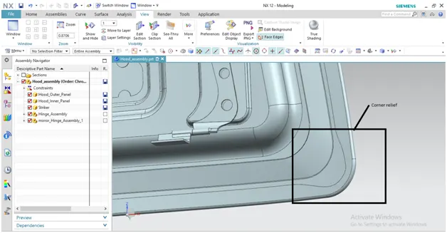
- Corner relief: There are many types of rolling process but in hoods roller hemming used. In this process the roller will be rolling over the edges of the outer panel to close it with the inner panel. These rollers will be rolling over 2-3 times for perfect closing. However in corner areas roller can’t tighten the part perfectly. This is why we give relief at the corners.
- Finally add thickness of 0.75 mm to the hood inner and outer panel
Mastic Sealant
The mastic sealant is an elastic member that behaves like a rubber. It is placed between hood’s outer panel and inner panel. It will have an influential area of about 80 mm.
Conclusion
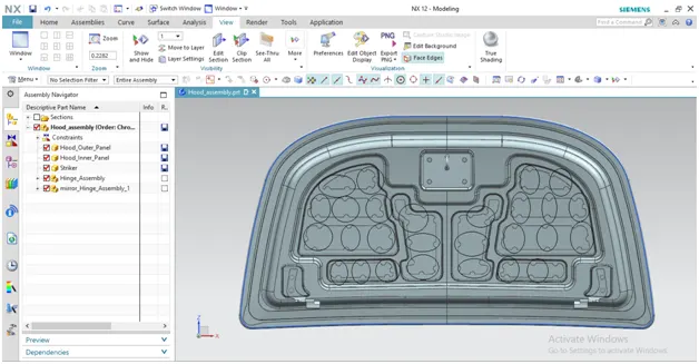
All the components of the hood are designed as per the given dimensions and industrial standards.