Hood design-Week 2
Automotive Design of Car Hood by Using NX Cad
Objective – To design and model the car hood with inner panel, outer panel and required reinforcements by using NX Cad.
Parts to design –
- Inner panel
- Outer panel with hemming
- Positioning the reinforcements
INTRODUCTION:
Data to be used:
Outer Panel Thickness = 0.75mm
Inner Panel Thickness = 0.75mm
Reinforcement Thickness = 1.5mm
Sketch:
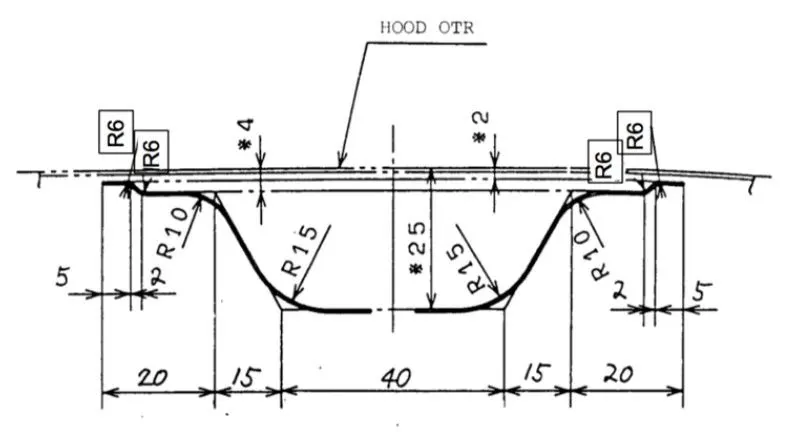
Hood: The car’s hood consists of an inner and an outer panel. The inner panel provides strength, while the outer panel is just a metal cover. The underside of the hood is often covered with a sound-absorbing material. Some high-performance cars have ‘hood scoops’ which channel outside air directly to the air filter, which gives improved performance and efficiency. Hood is an important component of the front portion of the car which is used for many purposes.
Purpose of Hood:
- It is used to decorate front portion of the car and to add luxurious look.
- It is made aerodynamic in shape to reduce air effect.
- It is used to cover car engine, radiator and many other parts, therefore bonnet must be designed in such a way that all the maintenance parts should be ease of access.
- It gives a minimum impact of external disturbance on the engine.
- Reduce engine noise which helps for a quieter drive.
- It is fundamentally a reinforced skin panel with many safety and quality requirements.
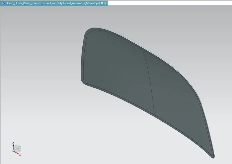
Outer Hood Panel: For designing the outer hood panel the class, A surface was provided as input and then outer edges were extend to form a flange which was designed in a manner which represents the hemming being done to hold the inner panel with the outer panel from the outside. At the corners reliefs was also designed so that the hemming operation can be performed easily
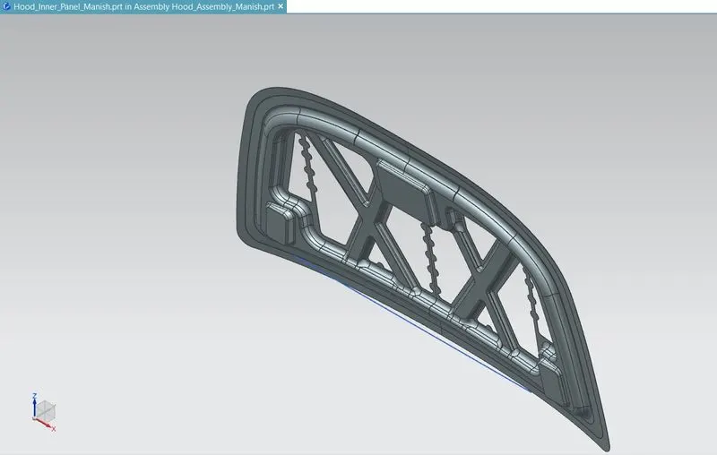
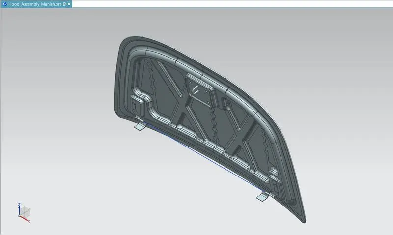
Inner Hood Panel: The inner panel of the hood acts as a reinforcement for the hood outer panel which provides strength to the outer panel. The thickness of the hood inner panel is 0.75 mm. In order to reduce cost and increase strength of the inner panel embosses are made on the Sheetmetal along with the cut-outs.
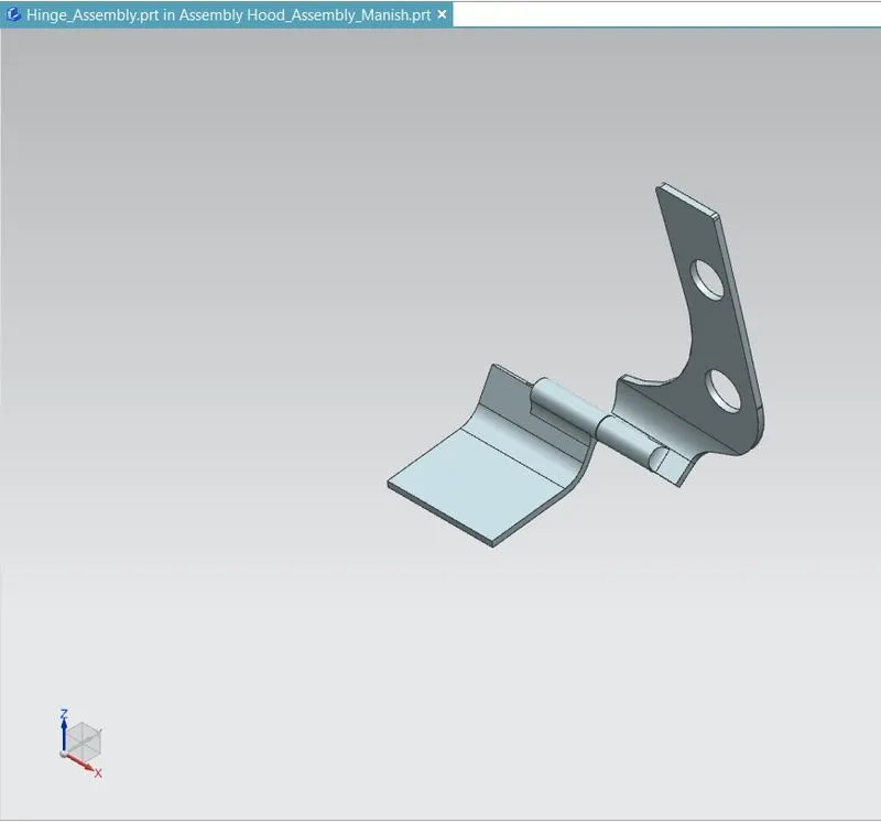
Hinge Assembly: Hinges are the assembly of components connected to the door and body of the vehicle, linked to each other and capable of rotating around the same axis. Conventional system consists of two hinges for each door, an upper hinge and a lower hinge.
Here one end of assembly attach to engine compartment and other to hood.
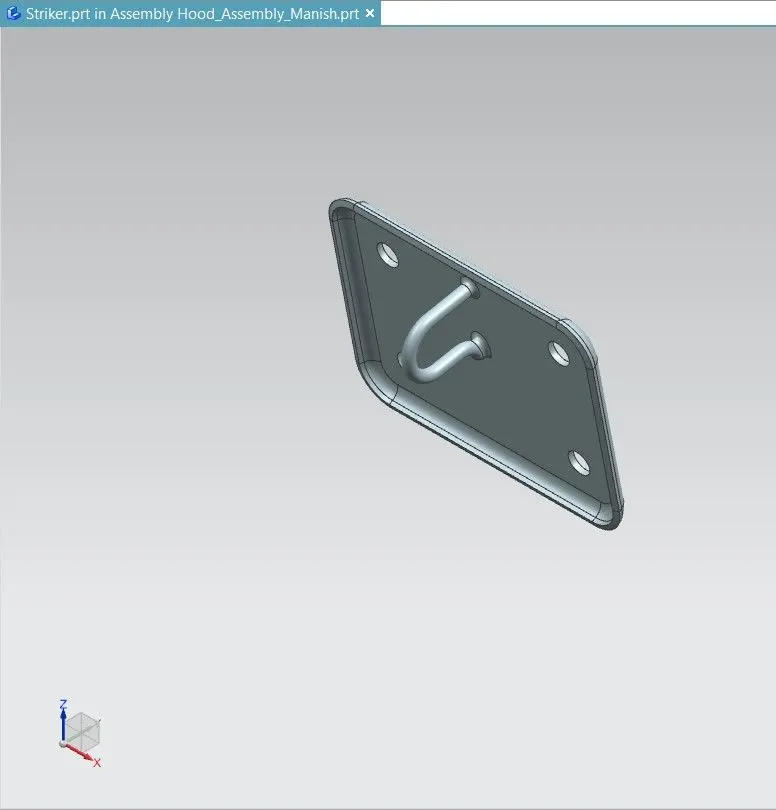
Striker: The door striker plates are installed in the door jambs, and precisely aligned with the door latches so that the latches catch onto the striker plate when the doors are closed. The door striker plate is made of hardened steel to resist wear as it is subjected to constant contact with the door latch.
Supports to hold the Hood:
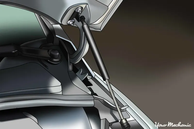
Gas Stay: A gas stay is a type of spring that, unlike a typical mechanical spring that relies on elastic deformation, uses compressed gas contained within an enclosed cylinder sealed by a sliding piston to pneumatically store potential energy and withstand external force applied parallel to the direction of the piston shaft.
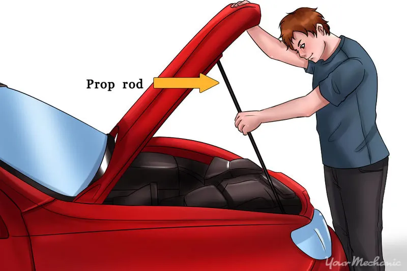
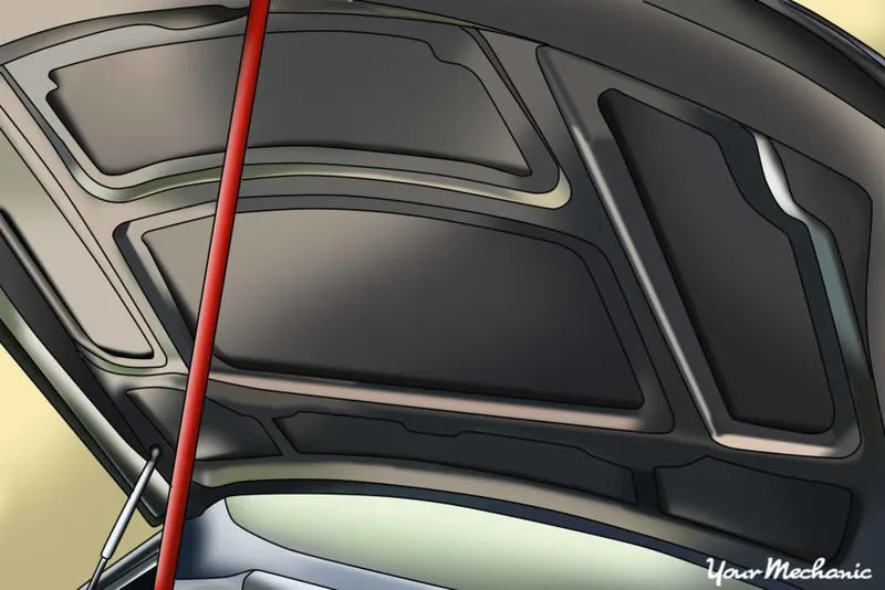
Support Rod: This is the most commonly used rod for opening and closing the hood at a certain angel. One end of the rod is hinged to the engine compartment and the other end is set free so that it can be locked to the hood inner panel when the hood is opened. This is usually used when the weight of the bonnet is small.
Safety requirements while designing hood –
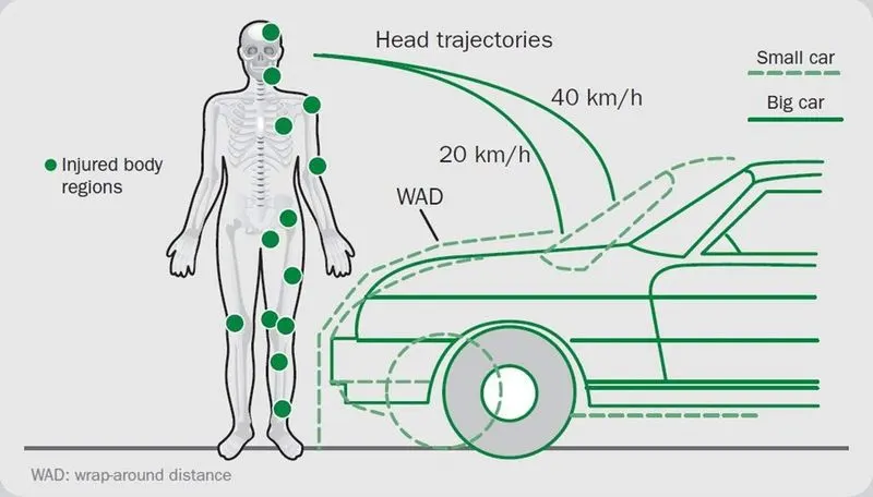
Car-pedestrian accidents account for a considerable number of automobile accidents in industrialized countries. Head injury continues to be more concerned with Automobile impacts. Because the head is the most seriously injured part in many collisions including in pedestrian automobile collisions. To reduce the severity of such injuries international safety committee have proposed subsystem tests in which head foam impactors are impacted upon the car hood.
The head impact analysis on the present hood of the car was done to study the response of the adult head form at two different locations. Structural and modal analysis for the same present hood assembly was done to observe the local and global stiffness. In order to reduce the head injury of the pedestrian the local stiffness over the area of head impact has to be reduced thus the new design of hood inner panel was focused on that and the structural and model analysis was done for the new design. The design with lesser local stiffness and similar global stiffness compared to the existing hood was finalized.
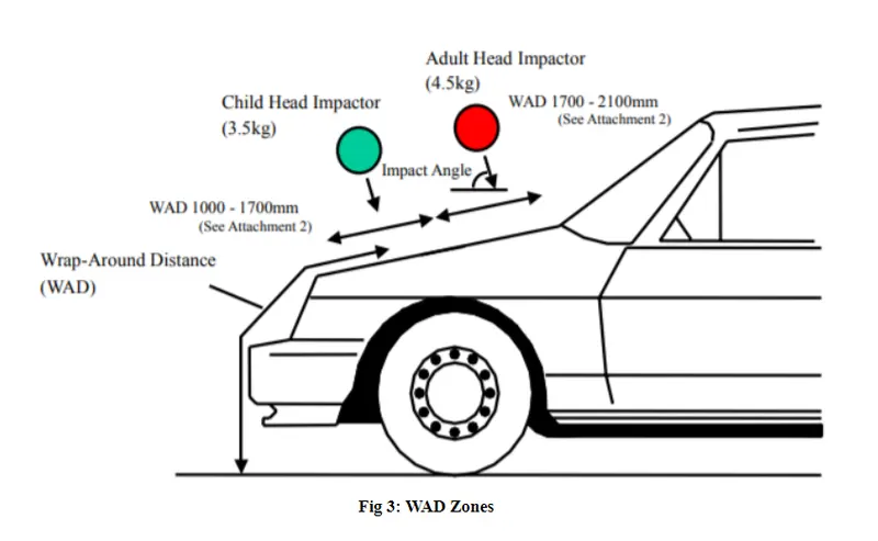
Pedestrian Safety: According to the requirements of the Australian New Car Assessment Program (ANCAP) for pedestrian protection, it needs to define zones of car hood for analysis, as shown in Figure 4. It can be noted that when the collision projection point locates between (Wrap Around Distance) WAD 1000 and WAD 1500, the head type will use the children head type. The adult head type will be used while the collision projection point locates between WAD 1700 and WAD 2100. In the collision projection point located at WAD 1000 when the children head type will be used.
Features used in creating all the parts of the hood design:
- Offset surface: The offset surface tool creates a copy of the selected surface at a provided distance and direction.
- Emboss: The emboss tool creates a punched surface of the selected closed contour. The punch is created from a selected surface containing the contour sketch/curve. A draft can be provided for the punch from either the end cap or the base surface.
- Trim sheet: The trim sheet tool splits the target surface along the intersection curve of target surface and the tool surface. The part of surface on either side of the intersection can be either discarded or retained as per the requirement.
- Through curves: This tool creates a surface between two different surface sections where the shape can change in between sections.
- Law extension: Creates an extended surface based on an open chain contour or a closed contour on the selected target surface. A draft can be provided for the extension.
- Face blend: Creates a curved blend or fillet along two selected surfaces in a provided direction vector. The curve of the blend can be adjusted in terms of radius, width and continuity.
- Extend sheet: Creates an extension of the selected sheet up-to a provided distance.
- Offset in face: Creates an offset of a curve or edge on the target face up-to a provided distance and direction.
- Bridge curve: Creates a, arc between two intersecting or non-intersecting curves. The start and end points of the arc can be adjusted by providing a distance value.
- Project curve: Creates a projection of a selected curve profile onto a target surface. The surface can be linear or curved. The direction of projection can be adjusted by providing a suitable vector.
- Extrude: Creates a surface or a solid based on the selected sketch. The distance and direction vector can be provided manually. Extrude tool can only create a linear profile along a provided direction.
- Sew: The sew tool merges two or more surface bodies into a single sheet or a solid based on the requirement. Any gaps between the surfaces can be closed if they are within the set tolerance range.
- Mirror geometry: This tool mirrors a selected geometry along a plane or a face.
- Curve on surface: Creates a curve on a selected surface by providing the start and end points and their relation i.e., G1 Tangent or G2 curvature.
- Thicken: Creates a solid body with provided thickness and direction.
- Extracted body: Creates a body of the selected geometry that cannot be edited. It can only be changed by editing the parent features and rebuilding the extracted body.
Different Views Of Assembly:
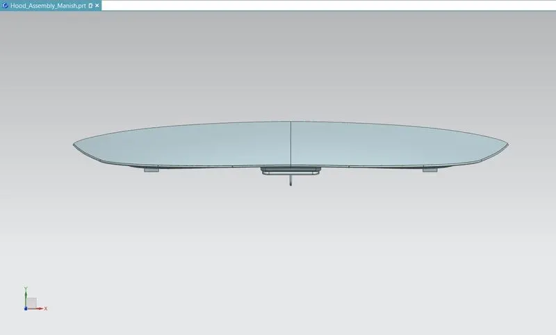
Top View
Isometric view
Left View
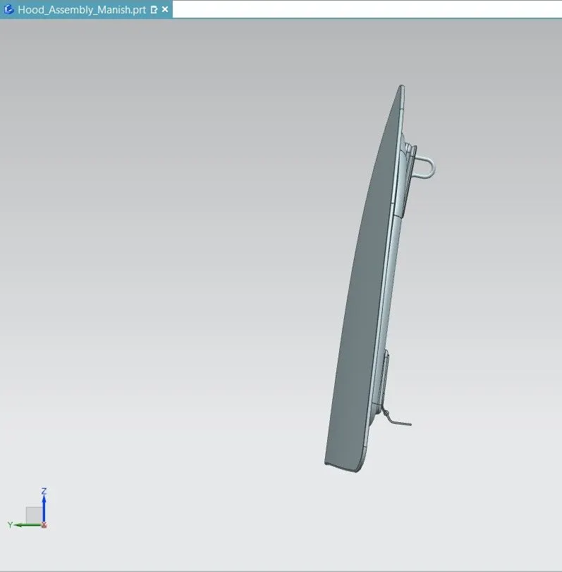
Front View
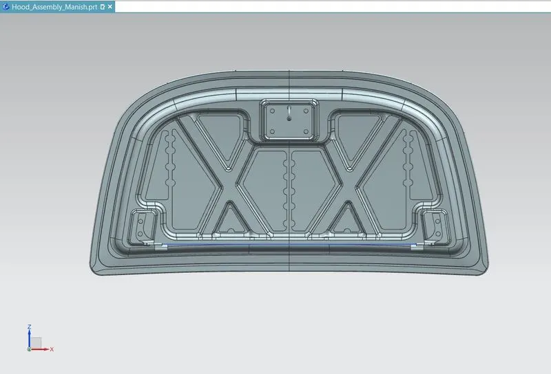
Right View
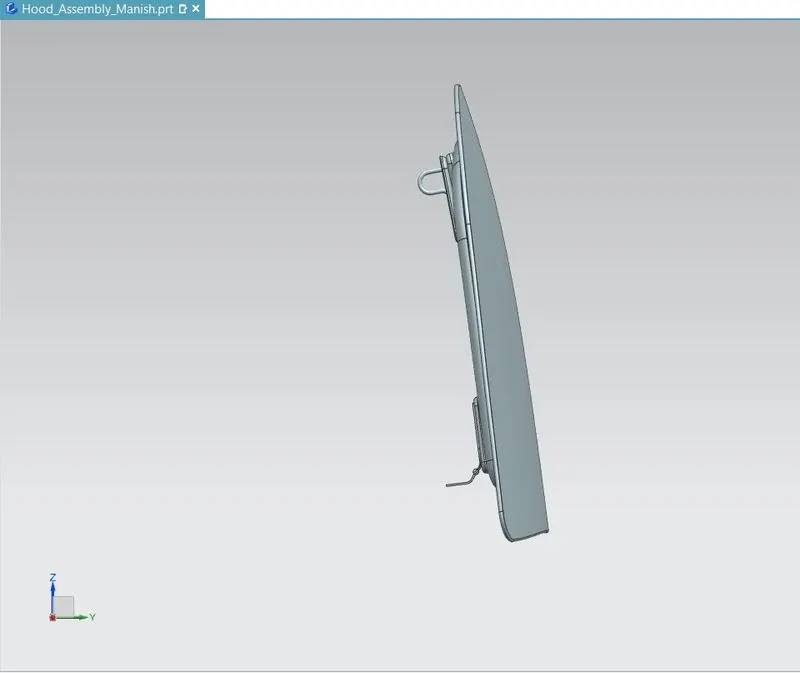
Conclusion:
- The complete assembly of the hood outer and hood inner panel was designed as per requirement.
- The latch and the hinges were also placed at appropriate position by following a latch trajectory strategy.