Hood design-Week 2
AIM:
To Design Hood/Bonnet with the necessary reinforcement by following the master section mentioned with the design parameters
OBJECTIVES:
- To Design the Outer panel
- To Design the Inner Panel with Master Section
- To Design the Reinforcement for the striker and hinges
OUTPUT REQUIRED:
- A detailed report about the Hood Design which includes a detailed explanation about hood and its components, Latch Trajectory, Mastic Data, Emboss Definitions, Manufacturing process like Deep-Drawing and Hemming, and all the parameters followed in the design.
- Hood Thickness Information
- Outer Panel Thickness = 0.75mm
- Inner Panel Thickness = 0.75mm
- Reinforcement Thickness = 1.5mm
- Hood Master section
- Hemming Data:
INTRODUCTION:
The hinged cover for a car's engine is called the hood or bonnet. On rear-engine and certain mid-engine cars, hoods may be opened to provide access to the engine compartment, often known as the trunk, for maintenance and repairs.
The outer panel, inner panel, latch and striker, hinge, and hood stay make up a conventional hood assembly. A hood stay is a device used to support a motorcycle's engine hood when it is opened. Opening the engine hood serves a variety of purposes, such as maintenance and repair work, part replacement, engine oil and cooling water replenishment, and room inspection.
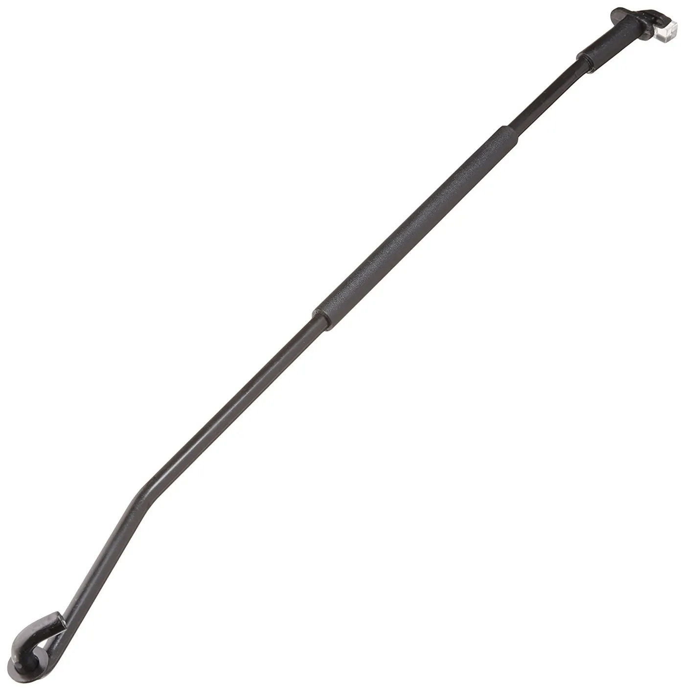
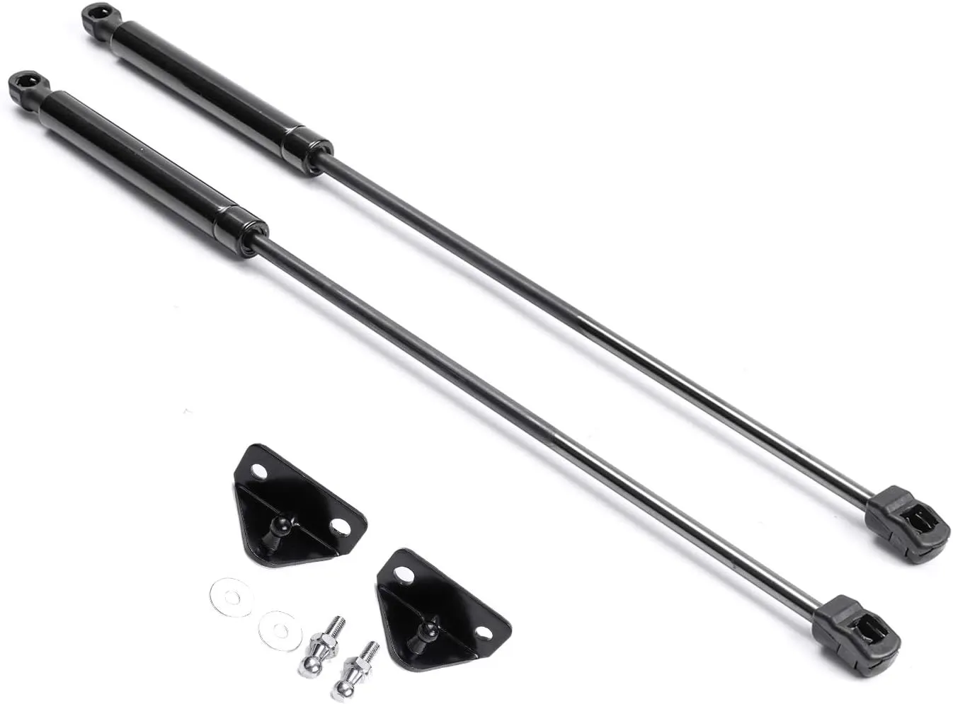
Support rod and gas stay hood stays are common varieties. While gas stays don't need any labor but are more expensive, support rods are manually controlled, inexpensive, and easy to construct.
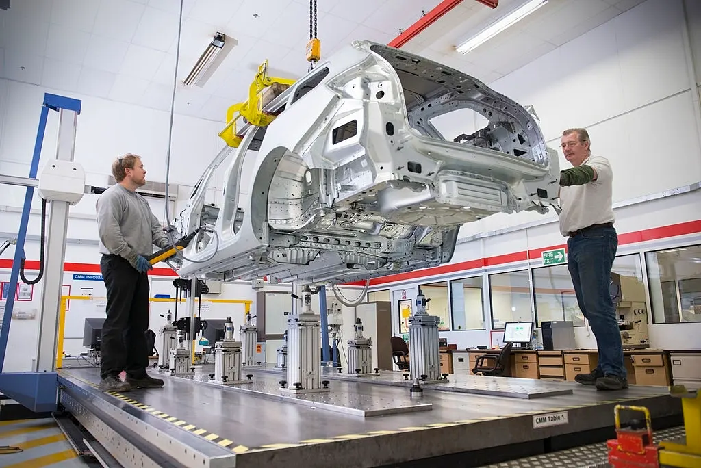
Usually, the hood is constructed from the same material as the bodywork. Aluminum and steel may be examples of this. The common sheet metal procedures used to manufacture hoods in the automobile industry include deep drawing, hemming, blanking, and piercing.
COMPONENTS:
The Hood panel consits of Hood Outer Panel, Hood Inner Panel, Reinforcements, Latches or Striker, Hinges.
- STEP FOR CREATION OF HOOD ASSEMBLY:
- Hood Outer Panel:
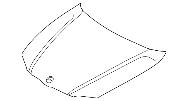
An automobile's Hood Outer panels are its decorative components. The skin for the Outer panel is provided by the style team. The hood's size, form, and placement should all adhere to safety regulations. Therefore, pedestrian safety should be given more consideration while constructing the hood.
- First save the given file in the same folder and given name has Hood Design
- Now Load all the file in Assembly option on NX CAD
- Then Start the process first trim half the portion and create the bridge curve for the sharp edges
- Offset the boundary using the offset the face option
- Now create the bend surface for the joining both upper and bottom sureface using the law extention options and throught curve option also used
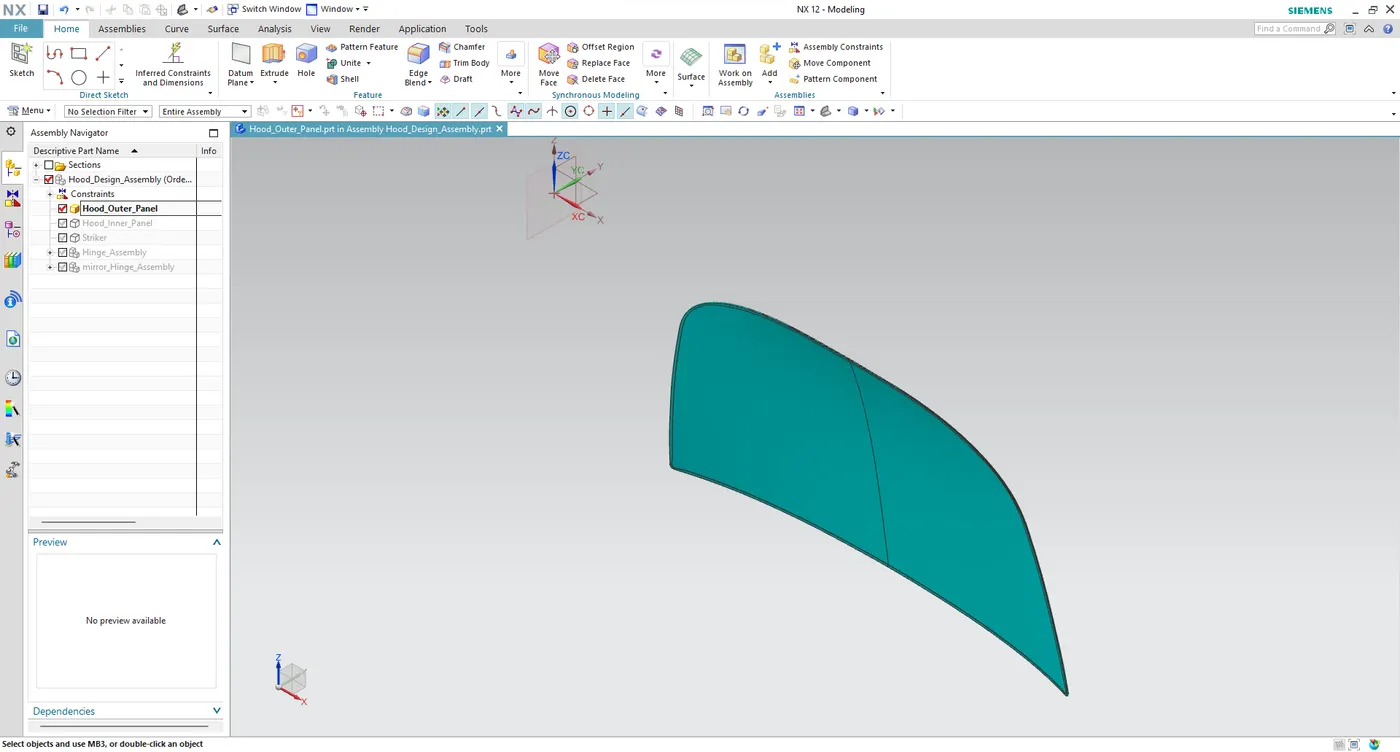
- Then create the thickness for the Hood Outer and values has 0.75mm
- then it look like were mention below
- Hood Inner Panel:
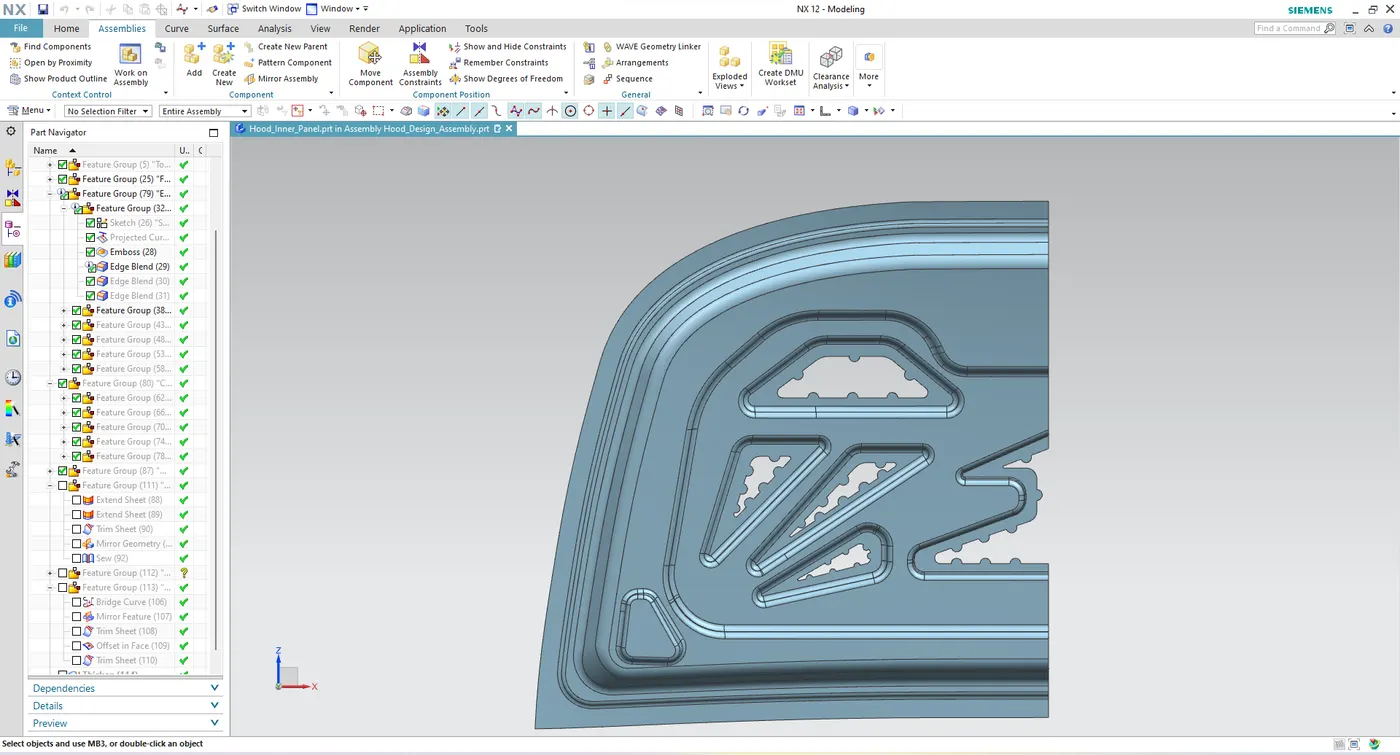
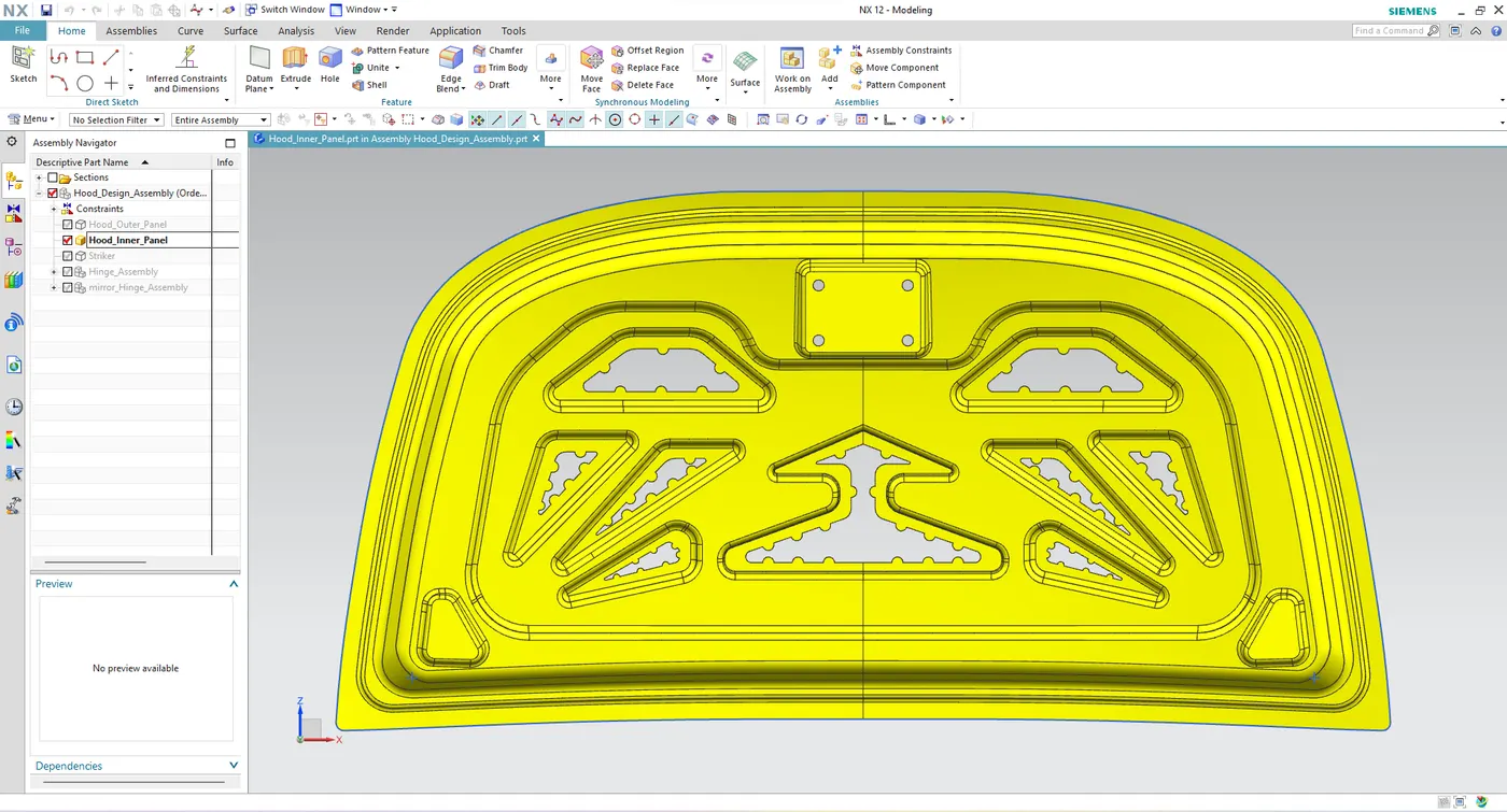
The Component that provides the outer panel its strength and stiffness is the inner panel. The original emboss form and size are represented in the master portion. After adjusting the placement, we supply the emboss for the latch and hinge components.
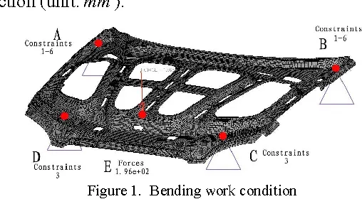
- Create the part in the assembly area and extract surface using the wave geometry linker
- Now Create the Tooling Axis using the sketch and the draw the lines
- Now create the flange using the option like OFFSET SURFACE, OFFSET THE FACE, TRIM SURFACE and also create the feature box given name has FLANGES
- Then Create the sketch for the EMBOSSES with pedstrain saferty and do in the features box given name has EMBOSS then cut out the embosses for the pedstrain safety
- Emboss Definitions:
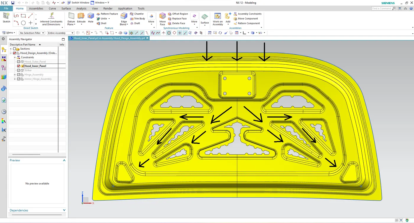
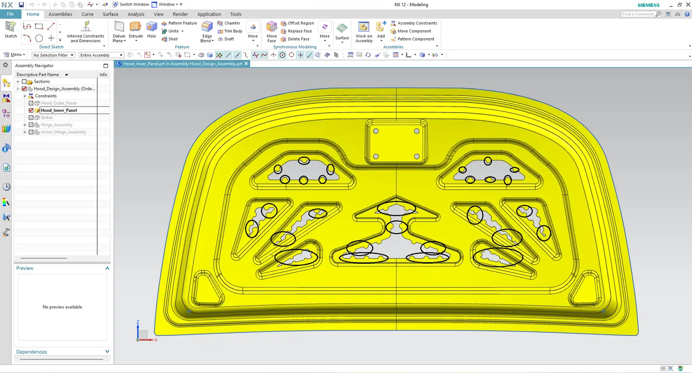
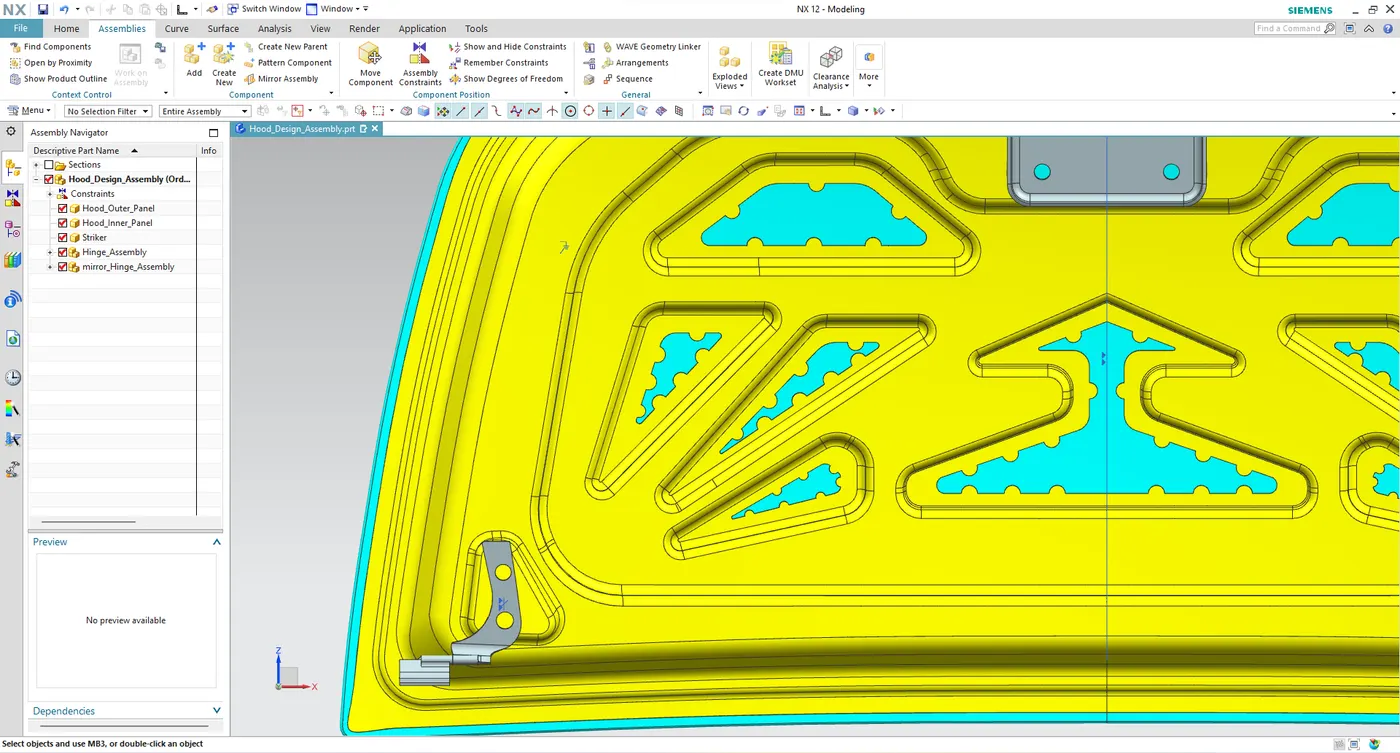
On the inner panel, we provide several embosses. These embosses allow us to improve the inner panel's rigidity. The direction of the force distribution that results from a frontal collision is also determined by the size and form of the embosses. Always disperse the force away from the passengers. The energy is channeled towards both sides of the automobile by the way the embosses are constructed in this illustration.
- Again create the sketch for the hinge mounting before what we do in the embosses creation same thing do for creating of Hinge Mounting
- Now create the mirror geometry from option were MENU-INSERT- ASSOCIATIVE COPY- MIRROR GEOMETRY and we got like this condition were mention below

- Now create the sketch for the Latch Trajectory for the analysing the open\close the hood
- Then same thing what we do for the Hinge Mounting process to create the striker mounting
- And we create the Reinforment usinng the Option called LINKED FACE, EXTENT SHEET, LAW EXTENSTION for the striker plate for the durability of the Hood
- Create the bridge curve for the sharp edges and given thicckness has 0.75mm
- Reinforcement:
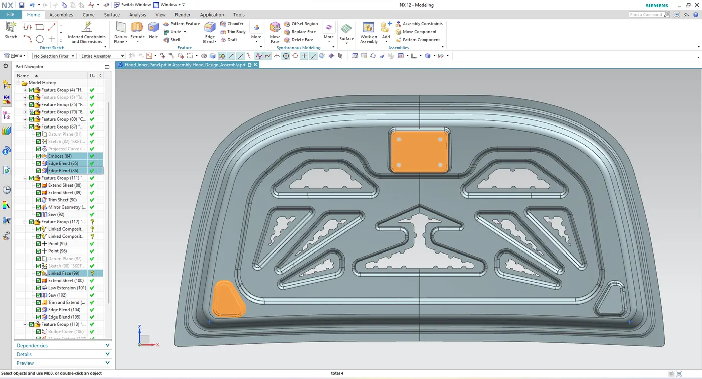
In accordance with the specifications of the design, reinforcements are supplied. It is primarily used to increase local strength at the hinge and latch areas. Reinforcements typically have a thickness greater than inner panels, with the value varying based on necessity and cost. The hinge and latch reinforcements have a 1.5 mm thickness each, per this design requirement.
- Latch Trajectory:
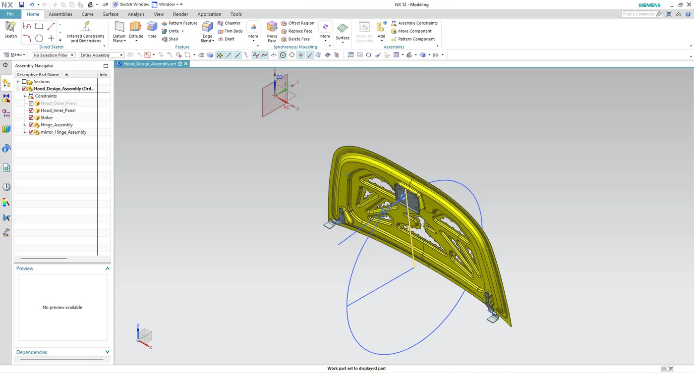
The circle that is drawn from the hinge axis point indicates the latch trajectory. The hinge axis point is located in its center. We can first repair the hinge or the lock. We should plot the latch's trajectory circle if the hinge location has been fixed. The striker axis via the striker tip should be tangential to the latch trajectory in order for the mating condition to be correct.
- Mastic Data:
Hoods often have a lot of surface area, and the only way to give hemming is through the border. Other connecting methods, including as welding and riveting, are not an option since they create markings on the outer panel that detract from the visual appeal of the piece.
Thus, the inner and outer panels' inner surfaces are adhered to using mastic sealants. Mastic sealants are rubber-like, elastic compounds. It is applied at certain locations between the inner and outer panels. Every mastic sealant patch has an impact on an 80 mm-diameter circular area. As a result, the mastic points are positioned to cover the more vibration-prone sections that are farther away from the hemming.
- Deep Drawing:
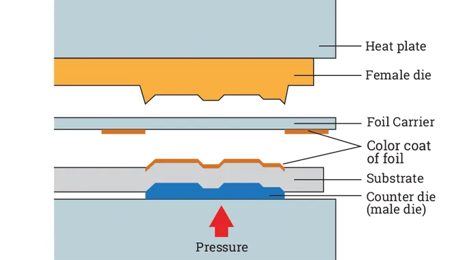
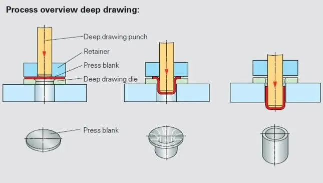
One of the most used methods in sheet metal forming is deep drawing. In addition to being used in several other industries, it is used in the automotive sector to make automobile body pieces. Combining compressive and tensile forces results in the shaping process known as deep drawing.
Punch force mechanically draws a sheet metal blank radially into a forming die. So, it is a material-retention process including shape alteration. When the sketched component is deeper than it is diameter, the drawing technique is referred to as "deep" drawing.
the part is redrew using a number of dies. The material retention feature causes a tangential compressive stress and a radial drawing stress to be experienced by the flange region, which is the sheet metal in the die shoulder area. Flange wrinkles are caused by these compressive forces, also known as hoop stresses. Using a blank holder, whose purpose is to permit regulated material flow into the die radius, can help prevent wrinkles.
- Hemming:
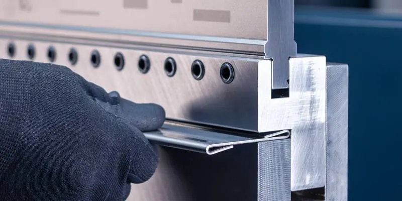
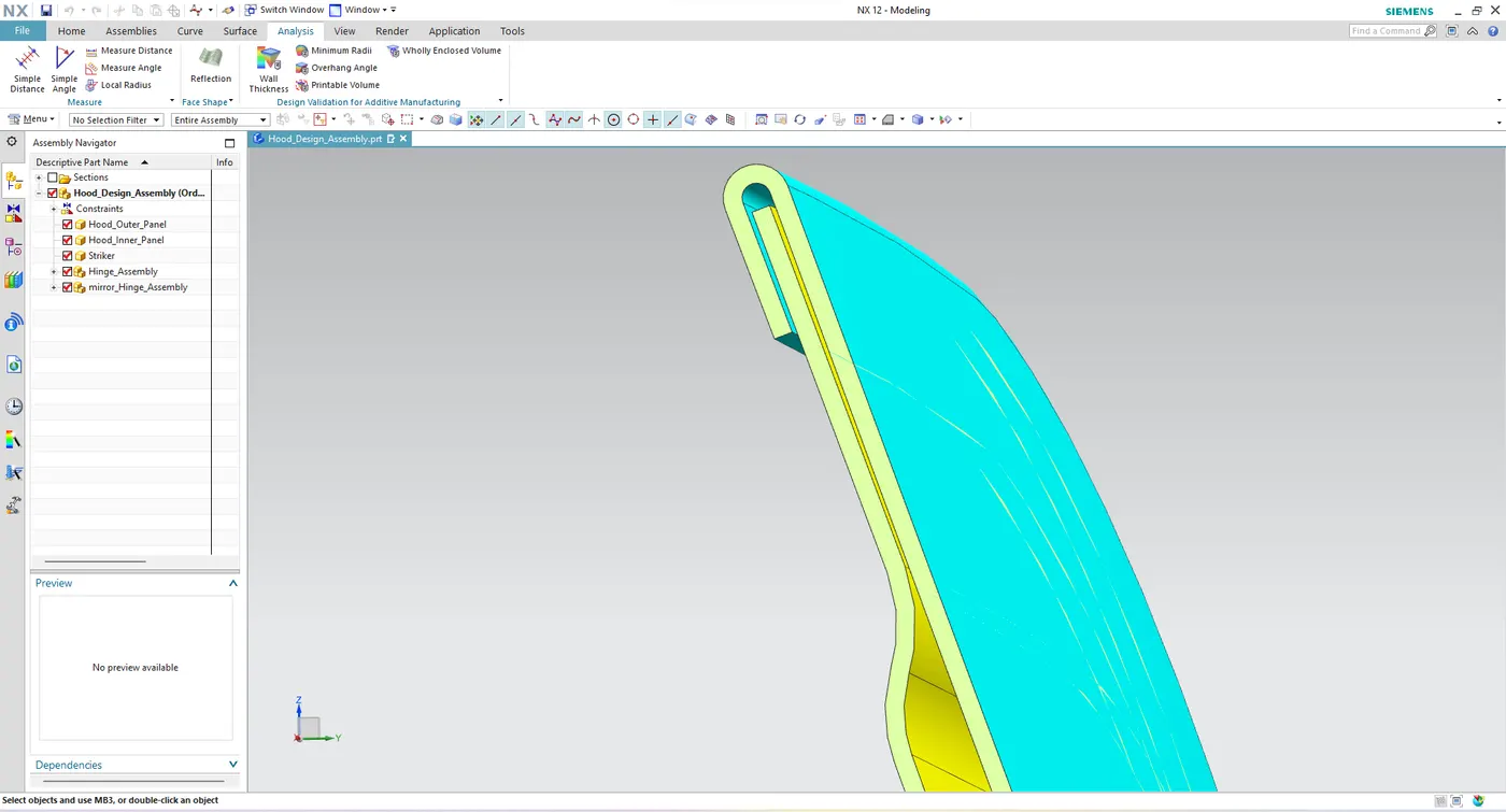
Hemming is a shaping process where a tight fit is achieved by folding the sheet's edges over one another or under one another. Hemming procedures are typically used to strengthen component edges, join parts together, and enhance part appearance.
Hemming is a secondary assembly step used in automotive component production, following deep drawing, trimming, and flanging procedures, to attach two sheet metal sections (inner and outer) together. This kind of assembly often consists of fenders, doors, trunk lids, and hoods.
There are two types hemming process
1. Conventional Die Hemming
2. Roll Hemming
- Convention Die Hemming:
Using a hemming tool, the flange is folded over the whole length in traditional die hemming.
- Roll Hemming:
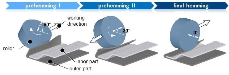
The method used for automobile sheet metal is called roll hemming. Using a hemming roller, roll hemming is done piece by piece. The hemming roller is guided by an industrial robot, which also produces the flange
There are many pre- and final hemming process phases that make up a roll hemming operation. Compared to conventional die hemming, roll hemming offers far reduced tool costs and greater tool flexibility. But because the hemming is done using a hemming roller that travels along a predetermined route, the cycle durations are substantially longer.
- Assembly constrains:
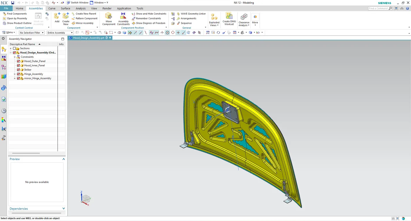
- First we do fix the Hood Inner Pannel using the ASSEMBLY CONSTRAIN option then Align the Hinge Assembly with Hood Inner Panel with touch Align type in the Assembly Constrain Option
- Now align the Striker Mounting with the Hood Inner Panel with Touch Align type in the Assembly constrain option
- Then we got like this contion were mention below
- Files:
- Those files were uploaded in the browse option and images also in same file and name has "Challenge 1 (Hood Design).zip"