Hood design-Week 2
DESIGN OF HOOD ASSEMBLY
AIM:
To design the hood inner panel and to fix the striker in the path of the trajectory of the hinge axis.
INTRODUCTION OF THE HOOD:
- The hood is also referred to as Bonnet. The hood is the hinged cover that rests over the engine bay of a front-engine vehicle. The hood is American English and the bonnet is Commonwealth English. Hood is one of the major BIW component of the car. It acts as a styling surface of the car. In designing the hood the designer should not only focus on the aesthetics of the hood but the designer also should consider passenger safety.
- Hood can open to allow access to the engine compartment,or trunk or rear engine and some mid-engine vehicles for maintenance and repair. The hood latch handle is usually located below the steering wheel, beside the driver's seat or set into the door frame.
HOOD CONTAINS:
- Hood outer panel(Thickness is 0.75mm).
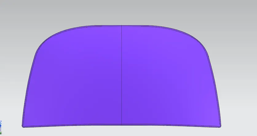
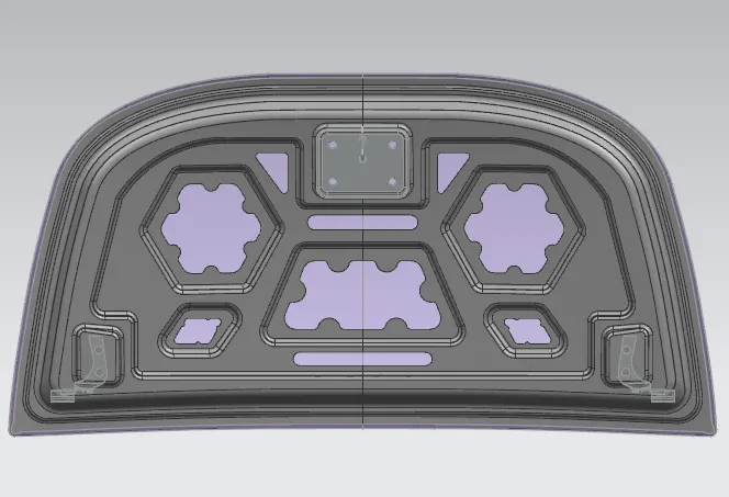
- Hood inner panel(Thickness is 0.75mm).
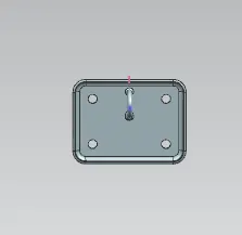
- Striker.
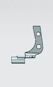
- Hinge assembly mechanism.
- The master section is created based on the requirements received from the marketability team and manufacturing requirements that we saw before. This image of the master section is used for the design.
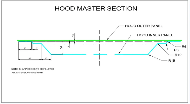
- The Styling Engineer will provide the outer surface of the hood to the design engineer as a design engineer we need to optimise the hood design such that the components meet all the safety criteris mentioned above without disturbing the styling surface.
DESIGN CONSTRAINS TO BE FOLLOWED BY:
- Passenger Safety.
- Pedestrian Safety.
- Manufacturing Feasibility.
- Positioing the Striker along the trajectory of the center of Hinge axis.
- Joining techniques of inner and outer panel.
PASSENGER SAFETY:
Whenever the frontal crash takes place in a car which will get affected will be hood. So, the hood must be designed in such a way that it should not come off from the body of the car and must absord the energy as for as possible and diverting the force to wards the side panel of the car. So that the amount of the force which is the sent to the cabin is lesser since the force is lesser the passengers will experience less amount of force so the passenger safety is achieved.
Hood inner panel plays major role in dissipating the force away from the passengers. It is completely depending upon the emboss which is created in the inner panel. The force will completely move along the direction shown above minimising the force exerted towards the cabin. A typical emboss is shown below.
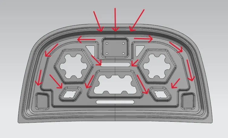
Since the emboss have move curved surfaces it will also absord the energy transferred during the collidion occurs.
PEDESTRIAN SAFETY:
Safety of the pedestrians need to be considered during the design as per the NCAP Euro assessments.
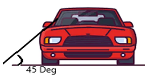
The hood is of two types based on the side reference line. Side reference line is a imaginary line drawn from a ground at angle of 45 degress. If this line falls on the fender then the hood id inlaid hood and if the line falls on the hood, then hood is wrap around the hood.
Child and Adult impact area on the hood are defined by the wrap around distance WAD.
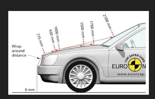
Area between the wrap around of 1000 to 1500 mm is the child head impact zone and from 1500 to 2100 WAD is the adult head impact zone.
Now since we know the zones where the pedestrians going to hit as a design engineer, We must make sure that they are experiencing the least force such that they were not getting any severe injury without compromising the strength of the hood so that passenger safety is also assured. For this reason the inner panel is kept at 25mm from the outer panel and creating the embosses is to improve the strength of the hood.
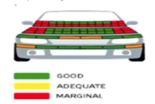
Head impact area will be typically looks as shown in the image is defined based on the side reference line and the wrap around distance. These zones will get RED,YELLOW or GREEN ratings based on the head injury criteria.
Calculated using the expression.
a = Acceleration of the head during impact
t2-t1 = interval between the beginning and end of the recording where the HIC value is maximum(Value can be maxmum of 15ms)
HIC<1000 region will be assigned green rating if HIC value is between 1000 to 1350 then the region will get yellow colour and HIC value more than 1350 then region becomes red.
MANUFACTURING FEASABLITY:
While designing a componet a design engineer must make sure that the component can producend by any means of manufacturing method with least amount of time,material,manpower and power. So that we can reduce the overall cost of car.
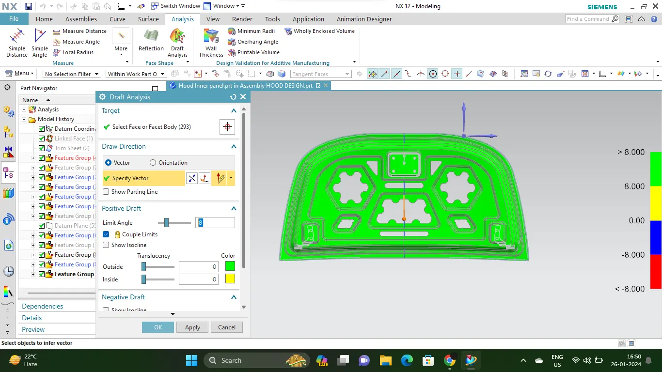
When the hood is considered it is manufactured by deep drawing at most of the time. Deep drawing is the process where the single sheet of metal is place over a die which has the desired shape of the final output and the sheet is pressed against it whit a tool. For the tool to come out from the part usually pressing relief of 5° to 9° will be provided during modelling itself.
In nx cad draft analysis can be done after modelling so that we can verify whether the product is manufactured by pressing or not. One side of the surface is highlighted by green and other side by red colour means that the model can be manufactured. Result of the draft analysis is below of the image.
POSITIONING THE STRIKER ALONG THE TEAJECTORY OF THE CENTER OF THE HINGE AXIS:
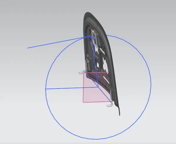
The striker needs to be place on the trajectory of the canter point of the hinge axis to ensure that it fix perfectly on the latch if not locking will not be smooth and affects the comfort and also it will create NVH problems. The striker is aligned using following steps:
- Drawing the line along the axis of the hinge.
- Creating the point of the mid-point if the line.
- Drawing the circle from the mid-point of the line to the latch where the striker will be mounted.
- Drawing the line from the center point of the mid-piont of the striker rod.
- Aligning the line's endpoint and the mid-point of the striker to the circle .
- The angle need to aligned so that thee angle of the striker is perpendicular to the line draw from mid-point of the axis line tp the mid-point of the striker.
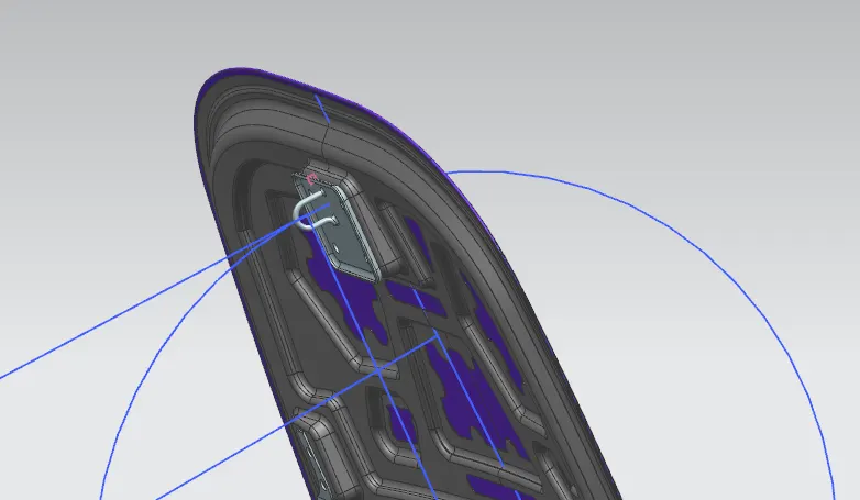
Now the striker will move along the trajectory of the circle drawn.
JOINING THE INNER PANEL AND OUTER PANEL OF THE HOOD:
Inner panel and outer panel of the hood should be joined rigidly without disturbing the styling surface of the hood which is the outer panel. Here we use special joining methods known as HEMMING and MASTICS.
Hemming:
Hemming is the process of wrapping the flange of the outer panel to the flange of the inner panel so that are fitting rigidly. After hemming process, the sealants were applied along the edge of the flange of outer panel so that water tightness is achieved.
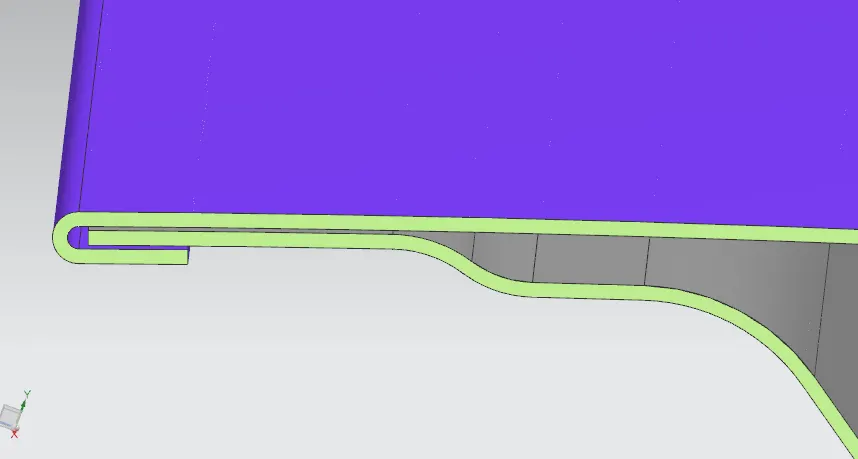
This image is cross section of the inner and outer panel joined by hemming process.
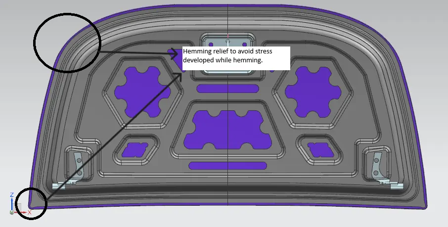
Usually, the reliefs were provided at the corners of the hemming flange to avoid the stress developed during the hemming process.
MASTIC POINTS:
Mastic points were the gluing points where the paste is applied between the inner panel and outer panel to join the panels. Each mastic point will stiffness up to 80mm surrounding. So mastics to be added in such a way that it covers entire surface of the hood. If the gap is less than 5mm between the outer and inner panel without mastic point it will cause vibration resulting in NVH problem.
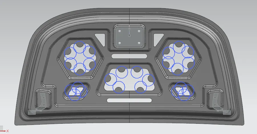
This image shows the mastic points where the paste is applied, and it will get hardened in further processes resulting in a rigid joint.
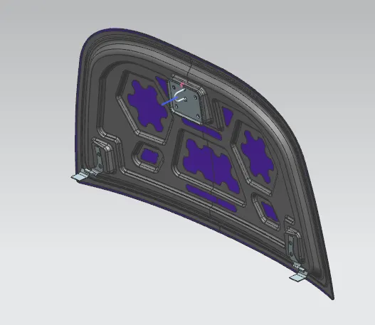
FINAL IMAGE OF HOOD ASSEMBLY
CONCLUSION:
Thus the hood is designed considering passenger and pedestrian safety as per the master section and striker also place in the path of trajectory of the hinge axis.