Hood design-Week 2
Hood design-Week 2
Objectives:- Design Hood Outer Panel, Inner Panel, and the necessary reinforcements by following the Master Section mentioned with the Design parameters explained in the videos.
Hood Thickness Information
- Outer Panel Thickness = 0.75mm
- Inner Panel Thickness = 0.75mm
- Reinforcement Thickness = 1.5mm
Car Hood:-
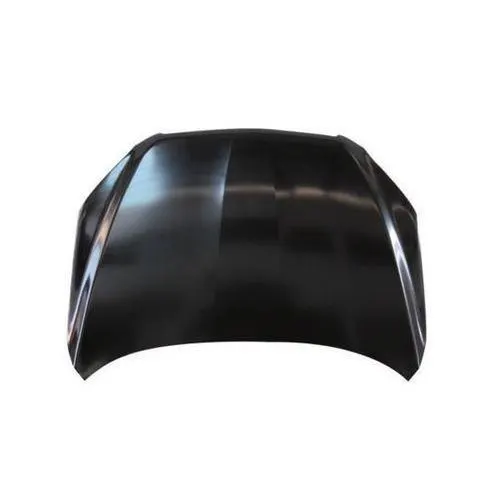
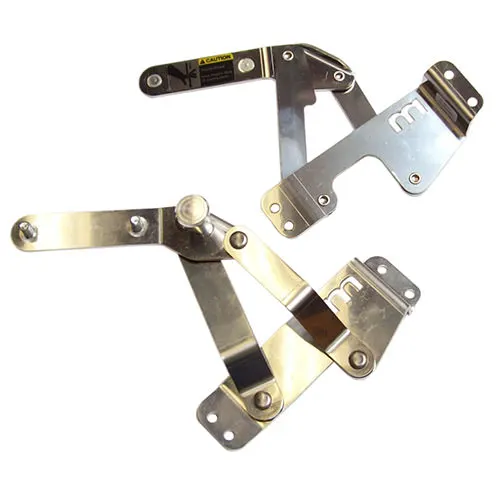
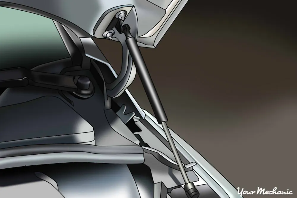
Basically car hood, also known as the bonnet, is designed to cover the automobile engine compartment. It is attached to the automobile's main frame with the help of hinge assembly and is helpful in the open-close process when any maintenance work has to be done around the engine. Usually, it is made up of thin steel sheets however it can also be manufactured by using normal fiber, carbon fiber, fiberglass, dry carbon, aluminum sheet, or any low-weight metal alloy depending upon the functional requirement. There is also a Support Rod present in the bonnet or sometimes inside the engine compartment to hold the bonnet so that one can inspect the engine compartment. Nowadays, hydraulic rods, also known as strut rods or Gas stay, are used instead of hinge assembly and strut rods, because sometimes the bonnet is so heavy to lift and also it does not require the Support Rod to hold the bonnet.
Terminologies for Car hood:-
Hood Outer Panel:-
Hood Inner Panel :-
Hood Hinge:-
Striker:-
Latch:-
Strut Rod:-
Mastic:-
We know that the hood comprises two main parts: a hood inner panel and a hood outer panel. The hood inner panel is enclosed below the outer panel and thereby provides rigidity to the hood. When these parts are assembled to form a hood a small gap remains between these two parts as they are both metal parts this may lead to noise and vibrations when the vehicle is in running condition which is undesirable to avoid this mastic sealant is filled between this small gap. Mastic sealant is a paste-like material that is applied on a surface and is hardened by heating.
Design Consideration of a Car Hood:-
While designing a hood several design parameters are to consider such as:-
1. Opening angle of the hood,
2. Support system for the hood,
3. Pedestrian safety rules, etc.
Hood head zone for striker locking:-
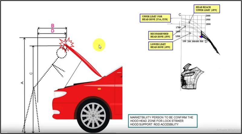
While designing the hood this parameter should be taken into consideration because when we open the hood to get access to the engine compartment to perform any operation while the hood is in the open condition the minimum height of the hood should be such that it does not collide or hit to head of the person who is operating. So, the height of a hood in open conditions should be more than the average height of humans in that region thereby no human gets hurt.
The following data should be used for deciding the Hood head zone
Hood Head Zone Selection Criteria
Pedestrian safety:-
While designing the hood, it is vital to consider the safety of pedestrians as when your car hits the pedestrian during a crash, it is very important to study the areas over the hood where different body parts of pedestrians are going to hit. we should also take into account the average height of adults and children while designing our hood. So, whenever a new car is been launched, all these safety parameters are checked by taking a crash test and studying the data obtained from it to make changes accordingly to follow pedestrian safety.
Euro-NCAP guideline for pedestrian safety
Force Distribution:
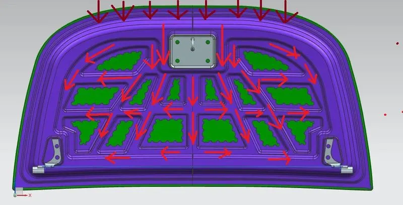
A good designer should always consider the safety parameters as a top priority, In the case of hood design, one should design the hood in such a manner that if the vehicle gets a frontal crash then all the forces must be distributed towards the hinge of the hood, as it is important to reduce the impact of the crash by diverting the force towards the hinges and thus safeguard the passengers in the vehicle.
Deep-Drawing:-
Deep Drawing is one of the most widely used processes in Sheet metal process. Apart from its use in many other sectors, it is applied in the automotive industry for the manufacturing of car body parts.
The deep drawing process is a forming process that occurs under a combination of tensile and compressive conditions. A flat sheet metal blank is formed into a hollow body open on one side or a hollow body is formed into a hollow body with a smaller cross-section. [DIN 8584]
Deep drawing processes are divided into three types:
- Deep drawing with tools
- Deep drawing with active means
- Deep drawing with active energy
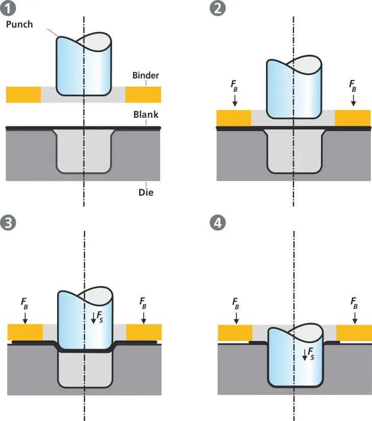
The figure illustrates the deep drawing process. The rigid tools consist of a punch, die, and binder. In deep drawing, the plate holder closes after the metal sheet blank has been inserted.
Then the sheet is clamped between the die and the binder. This process slows down the flow of the sheet while it is being drawn and thereby prevents wrinkles from forming under the binder. The punch stretches the sheet over the die radius and forms it in the die. The amount of punch force necessary for forming is thereby continually increased up to the lower dead center of the punch.
Whereas in pure deep drawing, there is no reduction of sheet metal thickness, forming is achieved in stretch forming purely as a result of a decrease in sheet metal thickness. Stretch forming is extensively used for the forming of only slightly curved parts with low depth of draw (e.g. roofs, doors).
When drawing complex car body parts in practice, there is usually a combination of stretch and deep drawing involved. It is necessary that the sheet metal is stretched as well as possible without reaching the material’s limits (e.g. splits, wrinkles).
There are approximately 300 to 400 sheet metal parts that fit together to form the body of a car. In order to manufacture high-quality sheet metal parts optimally for their particular use, specialized software simulates the complete deep drawing process
Hemming:-
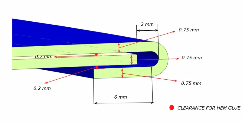
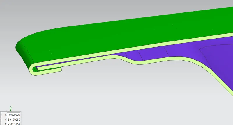
Hemming is a forming operation in which the edges of the sheet are folded over another part in order to achieve a tight fit. Normally hemming operations are used to connect parts together, improve the appearance of a part, and reinforce part edges.
In car part production, hemming is used in assembly as a secondary operation after deep drawing, trimming, and flanging operations to join two sheet metal parts (outer and inner) together. Typical parts for this type of assembly are hoods, doors, trunk lids, and fenders.
The accuracy of the hemming operation is very important since it affects the appearance of the surface and surface quality. Material deformations, which occur during the hemming process, can lead to dimensional variations and other defects in parts. Typical hemming defects are splits or wrinkles in the flange, material overlaps in the corner areas, or material roll-in. This is why it is important to use simulation tools in order to, on the one hand, better understand the hemming process and, on the other hand, significantly reduce the number of “trial and error” loops during tryout and production.
There are various types of hemming operations:
- Conventional die hemming
- Roll hemming
Conventional die hemming
Conventional die hemming is suitable for mass production. In die hemming, the flange is folded over the entire length with a hemming tool. Normally the actual hemming is a result of a forming operation in which the flange is formed with a hemming tool after the drawing and trimming operations have been completed. The formed flange is then hemmed in several process steps. These steps include, for example, the pre-hemming and final hemming depending on the respective opening angle of the flange. Production plants for conventional die hemming are very expensive, but the cycle times are very low.
Roll hemming
Roll hemming is carried out incrementally with a hemming roller. An industrial robot guides the hemming roller and forms the flange. Roll hemming operation can also be divided into several pre-hemming and final hemming process steps. Roll hemming is very flexible to use and tool costs are significantly lower as compared to those of conventional die hemming. However, the cycle times are much higher since the hemming is realized using a hemming roller that follows a defined path.
Emboss:-
An Embossing is created by pressing a female Die into a male Counterforce with the substrate to be embossed between the two. The Die and its matching Counterforce are aligned in registration and the substrate is positioned so that it is located in registration (the correct position). Then the Die and its Counterforce are brought together under huge pressure, distorting the substrate and forcing it to conform to the contours of the Die. The resulting sculptured effect on the substrate adds a new dimension to it.
Latch trajectory-
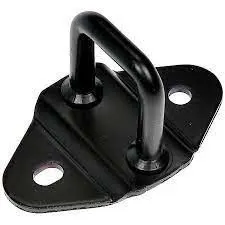
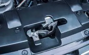
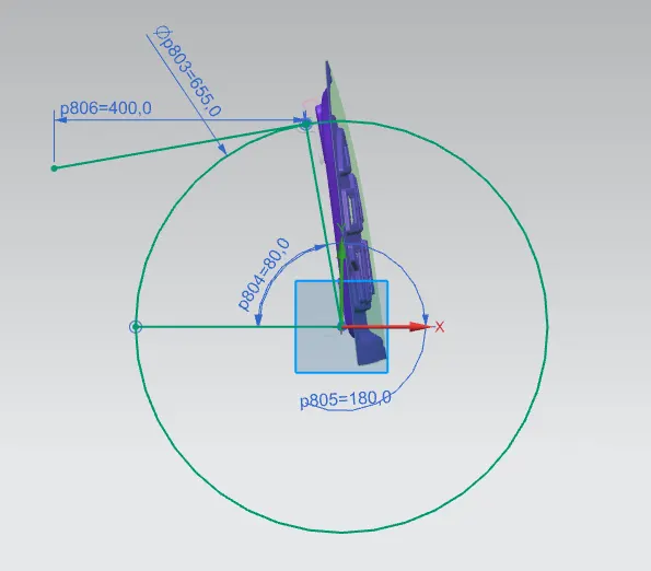
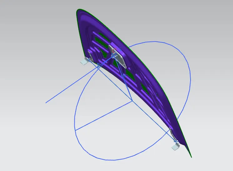
While opening or closing the hood, the latch must be perfectly aligned with the fixing or striker point. For that, the latch's trajectory must be perpendicular to the hinge axis.
The parameters followed in the design:-
We have used NX12 for designing the Car hood inner panel assembly. There are two methods to design any assembly in any CAD software- The bottom-up method and the Top-down method.
Bottom-up method:-
In this method first, we create individual parts separately and saved them in the same folder, and assembled them together by providing the necessary constraints. This is helpful in that condition where all necessary data is available to us and where no reference is required from the master section.
Top-Down method:-
In this method, we provided with master section and we have taken reference from it for further designing of other parts. First, we create an assembly file and save it in a newly created folder, and then make a copy of the master section in this folder. After that, we will open the master section in assembly operation using CAD software. Then in this assembly file, we will create the individual part file and create it using the master section as a reference.
The following are parameters provided by us to create Car hood assembly:-
Hood Thickness Information
- Outer Panel Thickness = 0.75mm
- Inner Panel Thickness = 0.75mm
- Reinforcement Thickness = 1.5mm
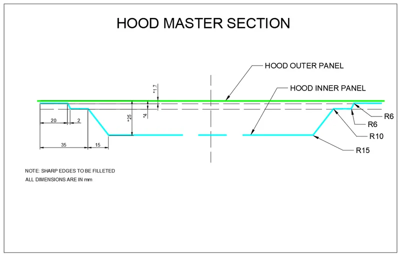
Master Section:
Hemming Data:
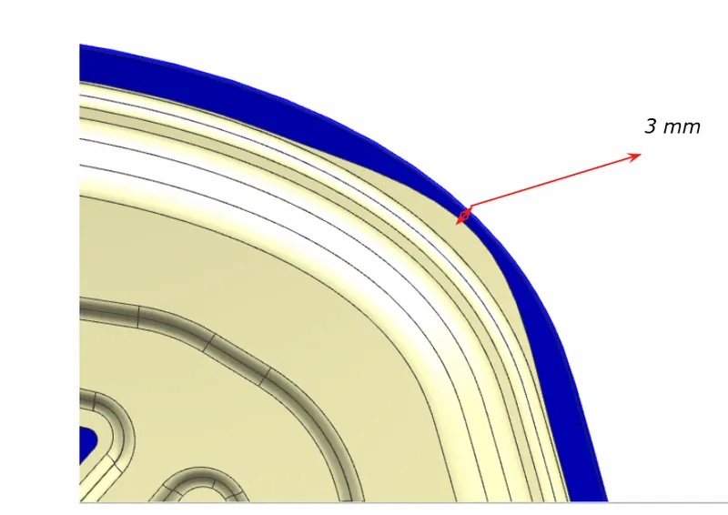
Relief rear section:
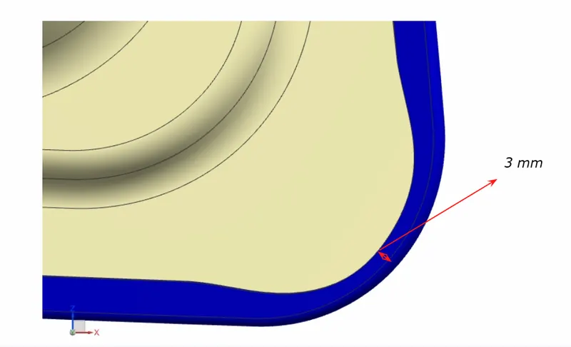
Front relief:
Procedure:-
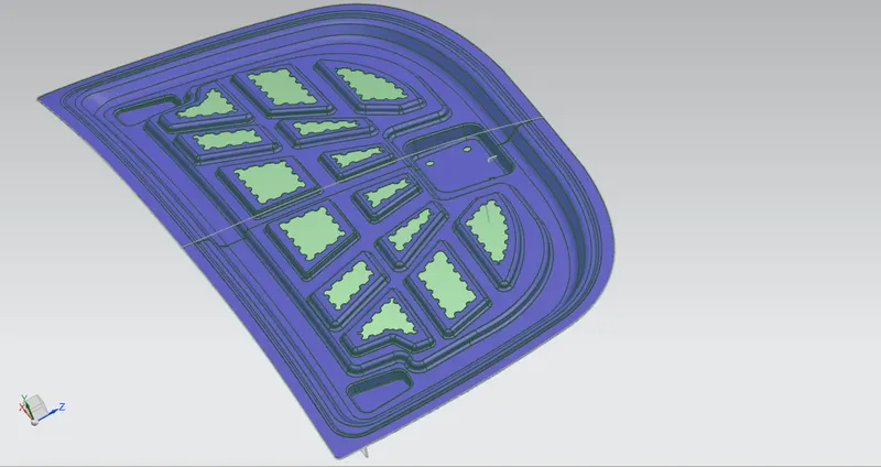
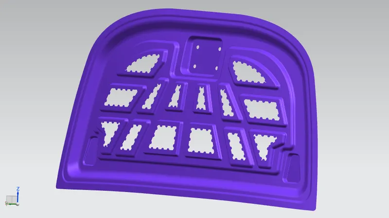
1. Hood inner Panel:

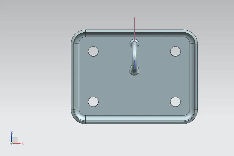
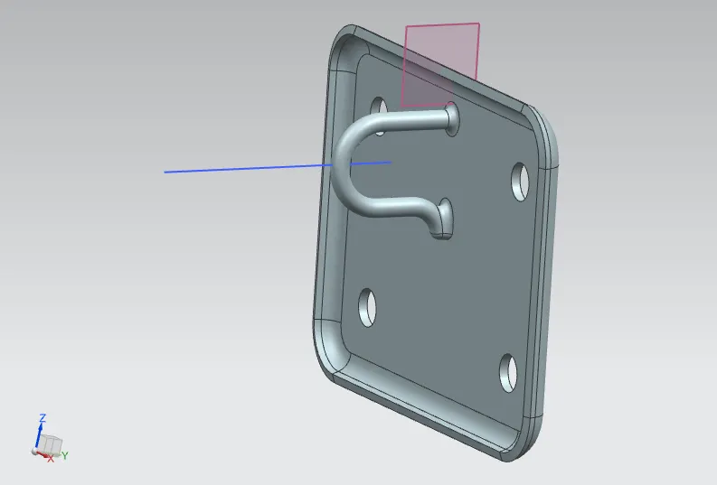
2. Striker:
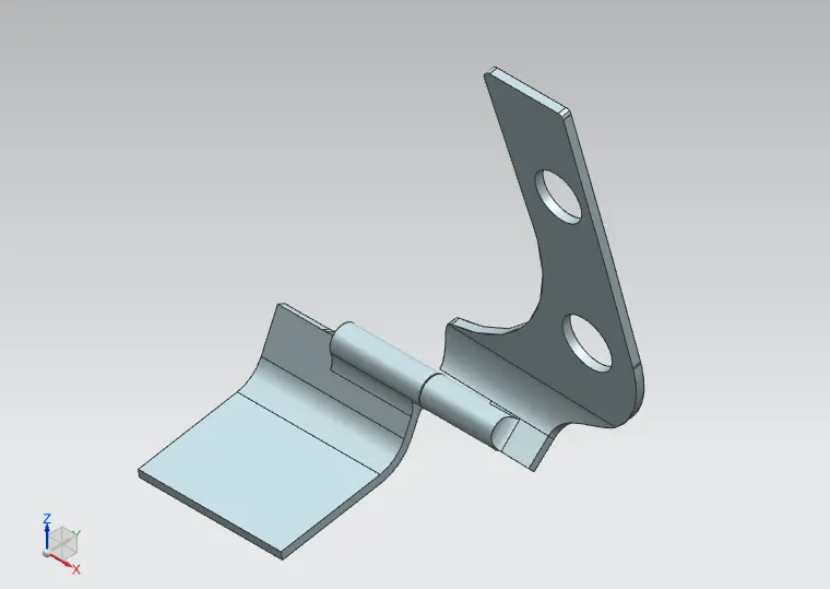
3. Hinge assembly:
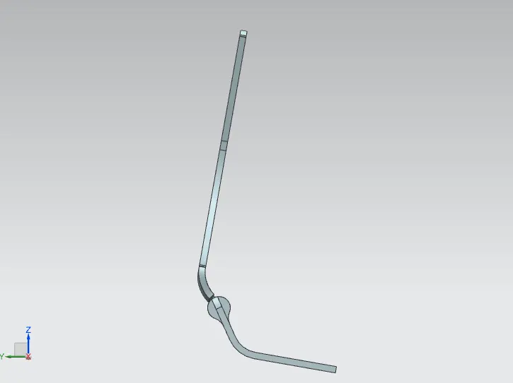
4. Hood outer panel:
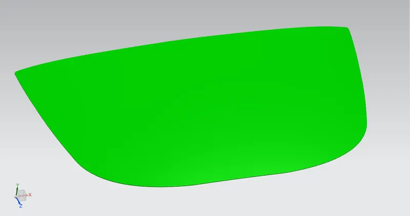
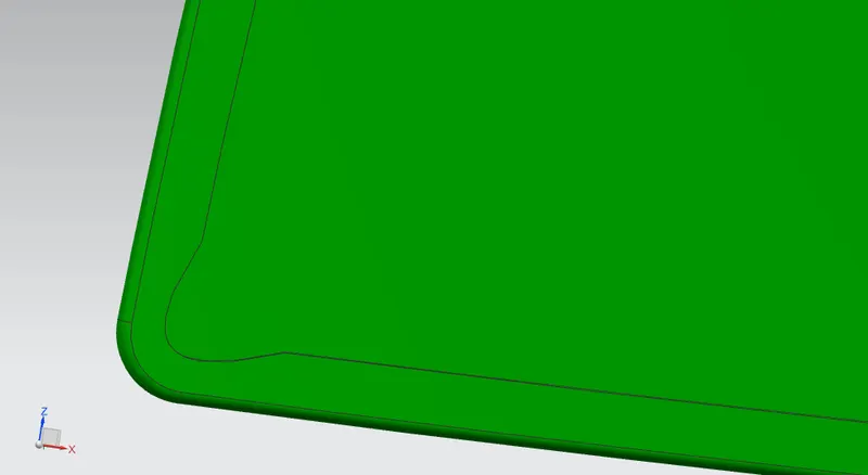
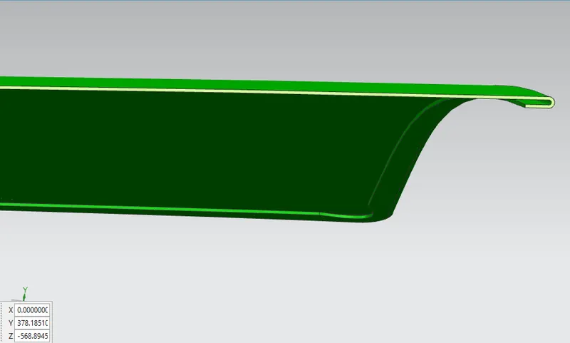
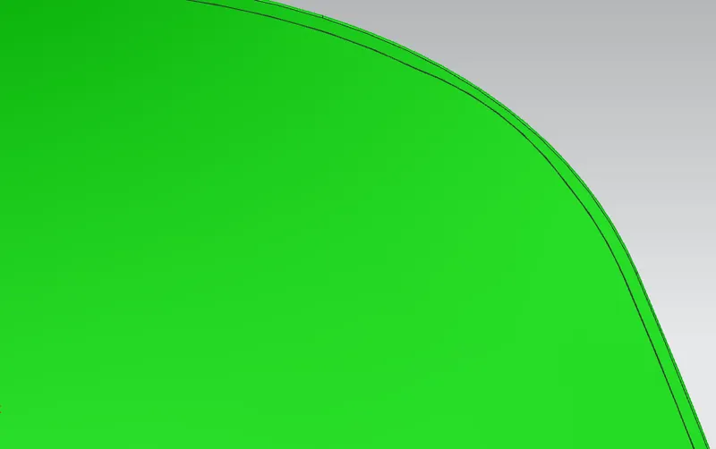
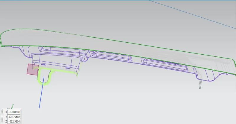
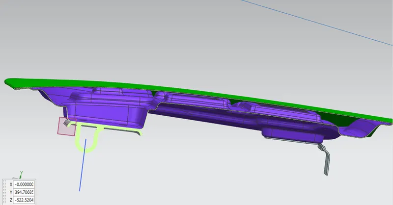
5. Final assembly:
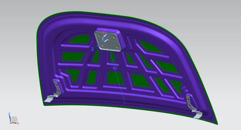
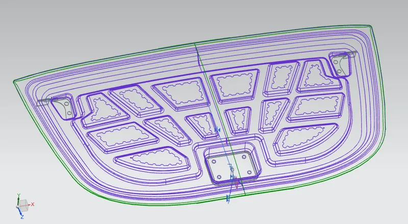

Note:-
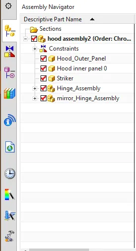
In zip folder open "hood assembly2" file.