Hood design-Week 2
Hood Design
AIM:-
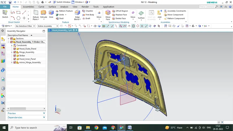
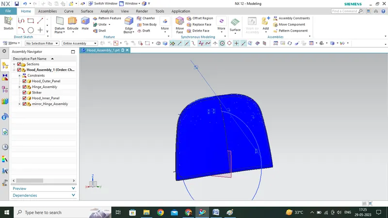
- Designing of the Hood OTR Panel, INR Panel and necessary reinforcements by following the Master Section given as per the design parameters.
- A brief explanation about the Hood and its components, Latch & Striker Trajectory, Mastic data, Emboss definitions, Manufacturing processes like Deep Drawing and Hemming, and all the parameters followed in the design.
THEORY:-
Parameters that are to be kept in mind preliminarily while designing the Hood:-
- Head Zone Criteria (Opening/Closing angle):- Depending upon the average height of a person in a country, we will decide the limits for the hood angle.
- NVH criteria (Mastic Sealant/Stiffener Pad)
- Pedestrian Head Impact Assessment
Head Zone Criteria:-
- Design a Hood Assembly by using the Hood OTR Panel Skin/Class A, Hinge Assembly & Striker given by following the prescribed guidelines.
- The Hood Panel of an Automotive Vehicle acts as a cover for the engine bay area and other related components in a front engine vehicle.
- Also considered another type of Door in a vehicle as it consists of an outer panel and an inner panel.
- The Inner Panel provides strength while the outer panel acts as the metal cover and aerodynamic styling surface.
Types of Hood:-
Based upon the type of Reinforcement is of two types:-
- Active Hood:- In this type, the strength and safety parts/reinforcements are provided separately on the hood.
- Passive Hood:- In this strength and safety parts are inbuilt on the hood.
Based upon the Side Reference Line (SRL) it is again of two types:-
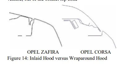
- Wrap Around Hood:- When the SRL touches the Bonnet.
- Inlaid Hood:- When the HOOD is laid inside the SRL.
Wrap-Around Distance:- It is the locus of the points on the front structure when one end of a flexible tape is held at the ground level (reference) and the other end is in contact with the front structure.
Side Reference Line:- It is the trace of the highest contact point between the straight edge inclined at an angle of 45 deg and the
- Types of Hood Stays:-
- Support Rod:-
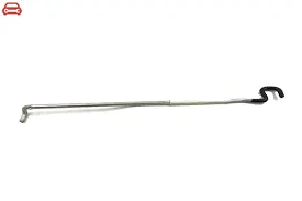
- It is a supporting rod used for holding the hood when it is in open condition.
- It is mounted on the Grommets present either in the engine compartment area or on the hood itself.
- No specific design input or consideration for the support rod and just have to ensure sufficient clearance around the engine compartment area and prevent rattling noises caused by the collision of support inside the engine compartment area when the car is in motion.
- Maximum curvature at the middle of the rod must be <35 mm which is a kind of standard defined after a lot of research and experience.
- Beyond this value, there are chances that the rod may get bent due weight of the rod, which isn’t my design intention.
- Mounting of the support rod is done on the opposite side of the Battery compartment to prevent collision or disturbance when the Battery is packed while the hood is open.
- Gas Stay:-
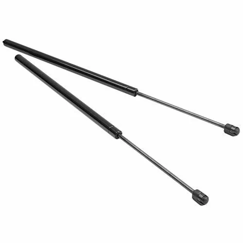
- Gas Stays are used on high-end performance vehicles where the hoods are very bulky.
- It automatically opens or closes just with an initial thrust to it.
- Ball Studs are used on both corners to fix the gas stay.
- Small reinforcements or brackets are used to locally strengthen the Gas Stay mounting area because the gas stay is an additional commodity.
- These reinforcements are provided to compensate for the strength reduction which occurs due to the addition of Gas Stay on the Hood Assembly.
- NVH Criteria:-
Stiffener Pad:-
A stiffener pad is provided in between the INR panel and OTR panel to locally improve the strength and minimize the NVH levels when the car is in motion.
The thickness or dimension of the stiffener depends upon the size of the Hood INR Panel and the amount of intensity and doesn’t have any particular shape.
Stiffener pads can easily be developed and can also be removed as a cost-reduction item at later stages of the project.
Reinforcement concept:-
- Whenever some weight is added to a material, there is local strength reduction in that area.
For eg:- Adding Latch & Striker on the Hood INR panel which is the locking mechanism for the Hood. So, to compensate for the strength reduction we add reinforcement to this area called as Latch and Striker Reinforcement.
- The thickness of the reinforcements is decided as per the loss we get in that area locally which is determined by the CAE Team or by CarryOver study on the previous segments of the vehicle and adopting it on the newer segments.
MASTIC Sealants:-
- Mastic sealants are provided in between the Hood OTR Panel and INR.
- It has an influence of improving the strength locally at around 50-80 mm diametrically and about 5mm longitudinally.
- Mastics get pasted when the Panel Assembly is put inside the Hot Bath before the Hot Furnace and the mastic gets hardened and thus it passes the INR and OTR Panel.
Construction of Latch Trajectory:-
- This approach explained below is valid for all the closure components like HOOD, ROOF, SIDE DOOR, BACK DOOR etc. which are all swinging parts.
- First, we’ll start positioning the hinges tentatively to get the Centre Point on the Hinge Axis.
- We’ll take the concept (pre-defined area) from our previous vehicle and position it at the striker region i.e., a cutline from the tipping point of the hood to the striker region and validate it whether it's right or not.
- The distance between the centre point of the striker to the centre point of the hinge axis acts as Radius and using that we draw a circle from which we infer two points:-
- The circle is the trajectory of my hood opening and closing.
- If the striker is perpendicular to my trajectory on the Latch and Striker region locally, then it means our hinge position is correct, or else, we need to move or hinge axis to get the perpendicular nature.
- The Striker section is common to all the segments of a particular vehicle but we have to define our hinge position tentatively and start drawing circles to define the trajectory of the Hood and also the hinge axis.
- In one situation, we have the perpendicularity achieved, which means our hinge axis and striker point are correlated.
- If the perpendicularity is not achieved, then the position of the Latch will get disturbed because it is positioned along the trajectory on the engine compartment area. Hence, we’ll not get a proper closing if perpendicularity fails.
- Due to perpendicularity failure, the hood closing becomes difficult and the customer feels it is a concern. Hence, resulting in the reduction of our sales volume.
Tests that are carried out in EURO-NCAP Assessment:-
- Head Impact:- It is given the topmost priority while designing the HOOD and is further categorized into two types –
- Child Head Impact
- Adult Head Impact
- Upper Legform to Bonnet Leading:- It tells us how much the waist area of a person will be affected during an impact.
- Legform to Bumper:- It tells about the impact severity when a person’s upper platform or lower leg form comes in contact with the Bumper during a Crash. It is categorized into two types depending upon the contact area of the Legform with the Bumper:-
- Upper Legform to Bumper
- Lower Legform to Bumper
- Pedestrian Head Impact Assessment:-
As per the IHRA (International Harmonized Research Activity) data, the major source of child and adult pedestrian head injuries is on the top surface of the hood of the striking vehicle. So the hood area should be designed in a way that can decrease the severe or fatal injury and the following four parameters below need to be considered:-
- Pedestrian Head Impact Zone
- Impact Point Selection (Under Bonnet Clearance)
- Test Method
- Head Injury Criteria (HIC)
Pedestrian Head Impact Zone:- From the top view along the vertical and horizontal directions on the hood, areas have been located after a lot of research for Child and Adult Head Impacts separately.
Child Head Impact Zone = 1000 WAD to 1500 WAD
Adult Head Impact Zone = 1500 WAD to 2100 WAD
Impact Point Location:-
- The manufacturer has to provide the Euro NCAP Secretariat with the HIC 15 or colour data at all the grid locations.
- Data must be supplied by the manufacturer before the testing of the vehicle begins.
- The predicted level of protection offered by the vehicle is verified by the EURO-NCAP.
- Alternatively, test points will be selected based on a worst-case performance basis.
Decided as per research.
Head Form Test Method:-
Based upon the HIC (i.e.,<=1000) values and other input parameters the Head From test method is carried out.
Pedestrian Head Injury Criteria and Rating:-
HIC (Head Injury Criteria)
HIC = `[1/((t2-t1))∫a dt]^2.5*(t2-t1)`
Where a = resultant acceleration (m/s^2)
t1 & t2 – two instants during the impact defining an interval between the beginning and the end of the recording period for which the value of HIC is a maximum (t2-t1<=15ms)
|
HIC Criteria |
Rating |
|
HIC = or < 1000 |
Green |
|
HIC = 1000 to 1350 |
Orange |
|
HIC = or >1350 |
Red |
- Depending upon the depth, at which a person’s head will go inside the hood upon impact, the grid colour locations are marked.
- In`[1/((t2-t1))∫a dt]^2.5*(t2-t1)` GREEN areas–the pedestrian’s head is going to have the least injury or soft landing.
- Collapsible mounting brackets are sometimes provided to increase the no. of green-coloured zones.
Emboss:-
- Embosses are provided on the Hood INR Panel to increase its Moment of Inertia while also getting the required functionality done.
- The design of embosses is per the designers’ freedom which is validated by the CAE Team.
- Once the designer stores the data, the CAE Team then checks for the Crash Analysis and the Drawablility situations.
- Must have a positive drawing direction for the emboss to get manufactured.
- Primary and Secondary embosses are provided on the hood's inner panel.
- Primary embosses are made by considering proper clearance between the primary emboss with the Striker and Hinge embosses.
- Secondary Embosses are made over the primary emboss so that the passengers should have a soft landing during an impact.
JOINING of Panels:-
For joining the panels, majorly two methods are used:-
- MASTIC SEALANTS
- HEMMING
Mastic Sealants:-
- Mastic Sealants are used to join the INR Panel with the OTR Panel and provisions for the placement of the Mastics are given on the secondary embosses.
- Sometimes, the gap between the INR and the OTR panel is matched to get the mastic influences.
Hemming:-
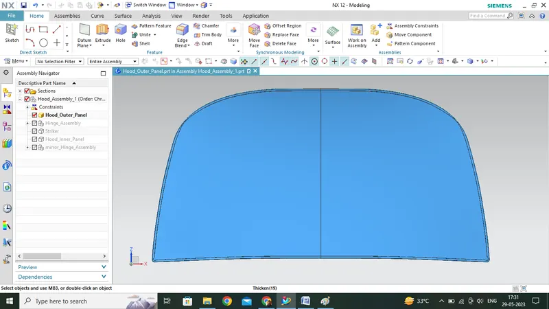
- Hemming is a kind of manufacturing process for joining the INR and the OTR Panel by bending and twisting the outer panel skin towards the inside, thus avoiding the spot welds.
- Some nomenclature is being followed while Hemming is done on the tool (NX CAD).
- Rollers are used in various passes for closing the OTR panel over the INR panel.
- At times, the sheet metal even vibrates when rollers are being passed and for this, we study the force that the rollers are applying on the Sheet Metal.
- At corners, Reliefs are provided as per the industry standards to maintain the Spring Back of the OTR Panel.
- The above standard of 3 mm relief at the corners is provided while designing on NX.
Additionally, some sealants are provided between the INR and the OTR panel to achieve water tightness.
Deep Drawing:-
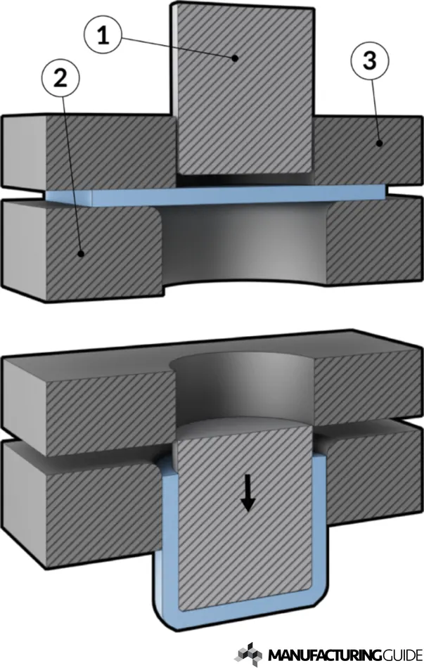
- This is a metal-forming process of stamping or pressing the flat sheet metal into a desired shape with the help of a die or some other stamping tool.