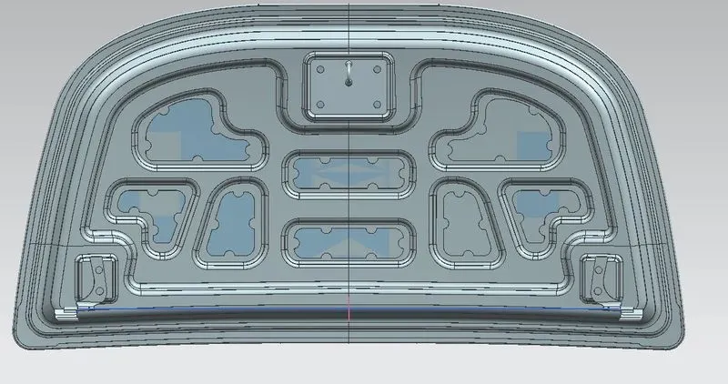
Hood design-Week 2
Objective:- Using the provided outer hood skin, master section, and design parameters, design the hood inner panel, hood outer panel, and reinforcements.
Introduction:- The hinged cover placed above the engine of the cars is called the hood. For the cars having engines in the front their hoods can be opened to provide access to the engine compartment for the repairement and maintainance purpose. From a design point of view, the hood must satisfy a number of requirements, including those related to safety of pedestrian, the hood head zone for the lock striker, force distribution in the event of an accident from the front (occupant safety), and manufactureability.The standard components of a hood assembly are:-
- Hood outer panel
- Hood inner panel
- Striker
- Hood stay
Design Considerations For Hood Of a Car:-
- Head clearance zone
- Consideration of Noise Vibration Harshness (NVH): The study and adjustment of a vehicle's noise and vibration characteristics, notably those of cars and trucks, is known as noise, vibration, and harshness, or NVH. While vibration and noise may be easily quantified, harshness is a subjective attribute that can only be assessed by using analytical methods that can produce findings that mirror the humans subjective perceptions.
- Pedestrian safety: The safety of pedestrians is a key factor in the hood's design. Hood is constructed with consideration for wrap-around distance and pedestrian head impact zone. The primary consideration in car designing is the safety of the occupant and pedestrian who is walking on the road. The head damage caused by the forceful collision of the head against the harder hood or the ground is the main cause due to which daeth of the pedestrian's happens in traffic accidents. As a result, a new inner hood panel that is less rigid and pedestrian-friendly is required. To lessen the power of the collision during an accident, the region near the head impact zone is made softer.
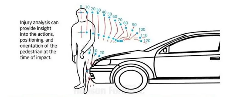
Fig 1: Pedestrian psition at the impact time
Design Parameters:-
- Outer Panel Thickness = 0.75mm
- Inner Panel Thickness = 0.75mm
- Reinforcement Thickness = 1.5mm
Master Data For Hood
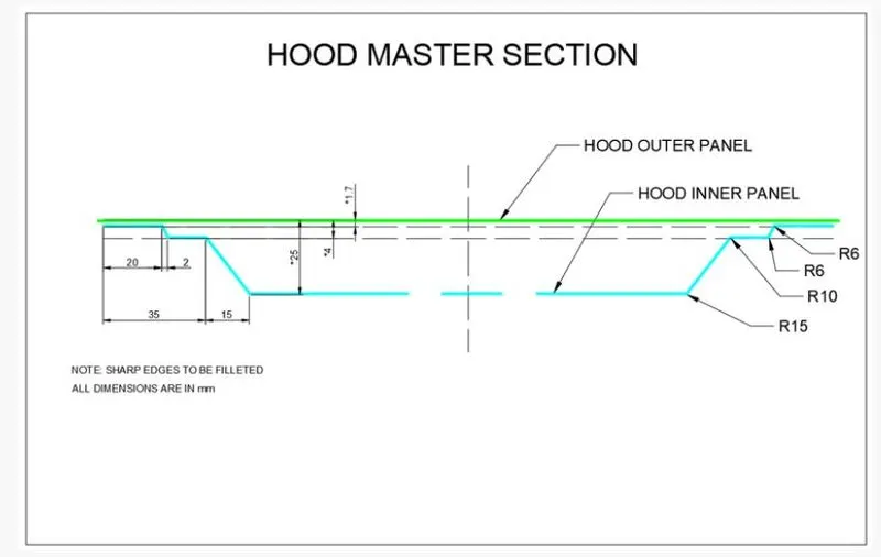
Fig 2: Master section for hood design
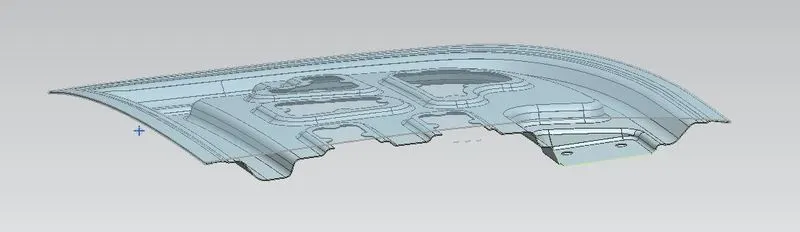
Fig 3: Hood Section View
Hemming Section
In order to obtain a snug fit, the sheet's edges are folded or folded over another area during the hemming process. Hemming procedures are typically used to join components together, to enhance a part's appearance, and to strengthen part edges. Hemming is a secondary technique used in the assembly of automotive components to link two sheet metal sections (the outer and inner) together following deep drawing, trimming, and flanging operations. For this kind of assembly, hoods, doors, trunk lids, and fenders are typical components. Since the hemming operation has an impact on the surface's appearance and surface quality, accuracy is crucial.
The two types of hemming process:-
a) Die Hemming
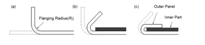
Fig 4: Hemming Process
b)Roll Hemming
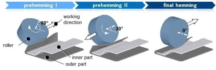
Fig 5: Roll Hemming Process
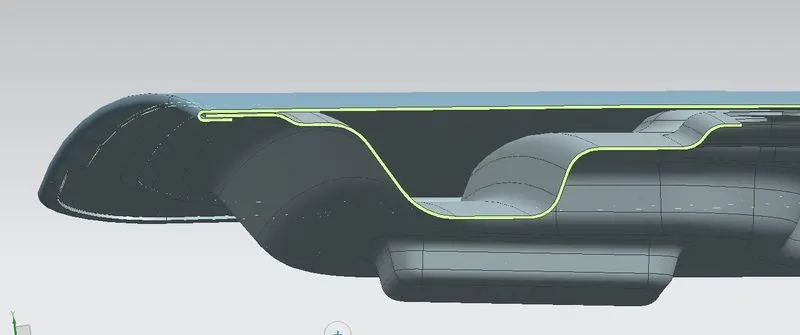
Fig6: Hemming Section View
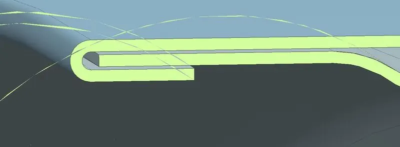
Fig 7: Close Hemming Section View
Deep Drawing
Hood Relief Section
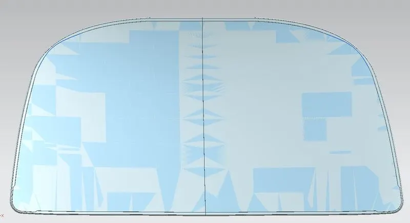
Fig 8: Hood relief
Procedure:-
Hood outer panel :- The outside panels of an automobile are its decorative components. The skin for the outside panel is supplied by the style team. The hood's size, location, and form should all adhere to safety standards. Therefore, pedestrian safety should be given more consideration while constructing the hood. Hemming is used to join the outer panel to the inner panel. Therefore, the requisite hemming flange and reliefs must be provided for the hemming process. To lessen the vibrations, we also provide mastic sealants between the outer and interior panels.
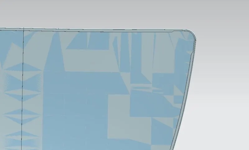
Fig 9: Hood Outer Pannel
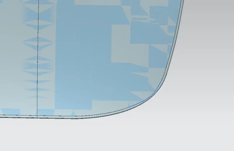
Fig 10: Hood Outer Pannel
Fig 11: Hood Outer Pannel
Hood inner panel :- The inner panel is what gives the outer panel strength and stiffness. The original emboss size and form are represented by the master section. After determining the placement, we then supply the emboss for the latch and hinge components.
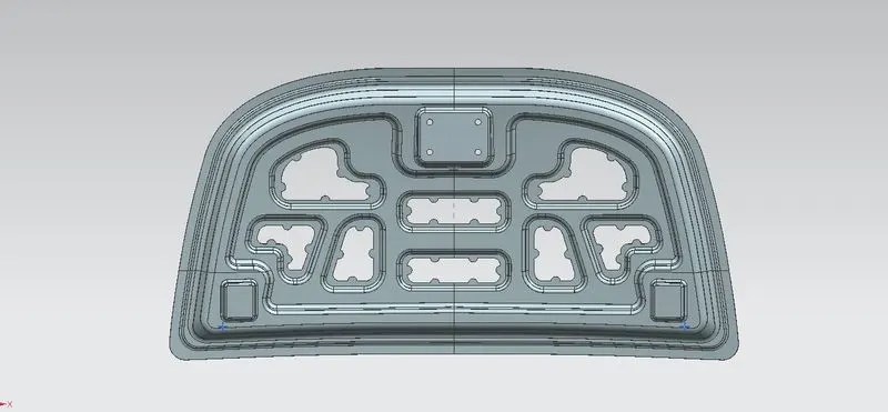
Fig 12: Hood Inner Pannel
Reinforcement :- According to the needs of the design, reinforcements are offered. It is primarily offered at the hinge and latch locations to increase local strength. Reinforcements typically have a thickness that is more than that of the inner panels, and their value depends on cost and demand. The hinge and latch reinforcements are given a 1.5mm thickness here in accordance with the design specification.
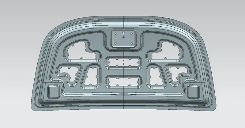
Fig 13: Latch Reinforcement
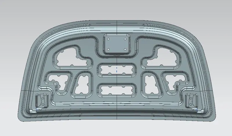
Fig 14: Striker Reinforcement
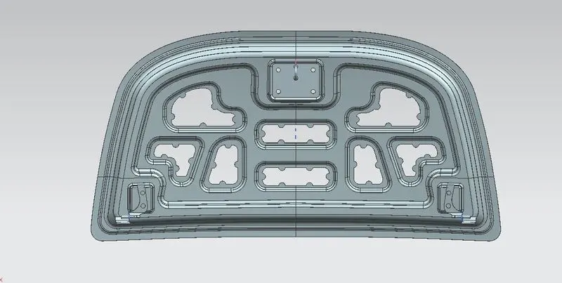
Fig 15: Complete Reinforcement Assembly
Latch Trajectory :- The circle formed by the hinge axis point provides the latch trajectory. The middle of the hinge axis is known as the hinge axis point. Either the latch or the hinge can be fixed first. If the hinge location has been fixed, the trajectory circle for the latch should be shown. The striker axis through the tip of the striker should be tangential to the latch trajectory for optimum mating conditions.

Fig 16: Latch Trajectory
Emboss
The inside panel features a variety of embosses. These embosses enable us to improve the inner panel's rigidity. The size and shape of the embosses also affect how the force distribution from a frontal collision is distributed. Always disperse the force away from the passengers. The embosses in this illustration are constructed such that the force is applied to the car's flanks.
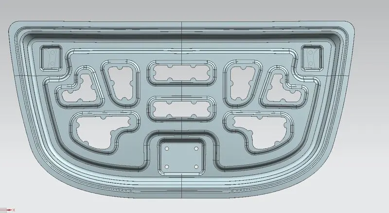
Fig 17: Emoss on Hood Inner Pannel
Final Assembly