Hood design-Week 2
HOOD DESIGN
1. First download all model and put them in a single folder
2. Now go to nx and open assembly window make new file name it as hood assembly
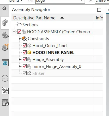
3. Now add component such as hood outer panel to this assembly.
4. This is the first step , referenig to the outer panel we will going to creat inner panel.
5. Make a feature group of hood outer panel to creat hood inner panel in part nevigator.
6. Name it as parent surface.
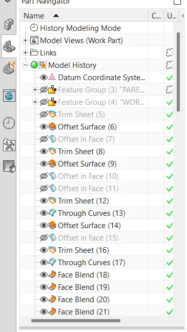
7. Trim the sheet into half selection plan to cut it
8. Now offset the parent hood outer panel to zero offset distance to make it as working surface
9. As the inner hood panel is symetric so we are making only half part .
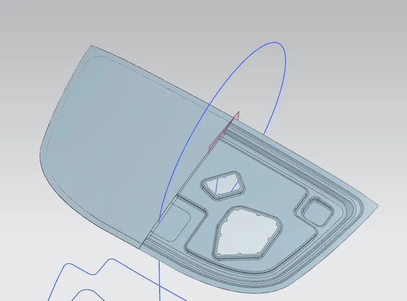
10. After looking at master section we will try to generate the different surface using offset command
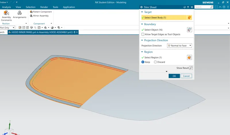
11. Fisrt offset the surface to 1.7 mm distance.
12. Using offset curve command ,offset the outer curve to 20 mm distance and using trim sheet command trim to get the surface.
13. Now offset the working surface to 4 mm distance.
14. Using offset curve option create two curves at offset distance of 22 mm and 35 mm.
15. Trim sheet to get surface as defined in master section
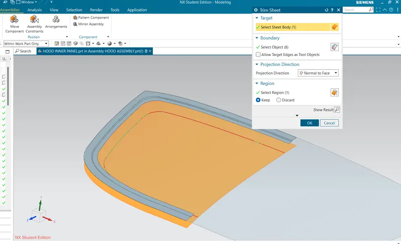
16. Now offset the working surface to 25mm distance.
17. Using offset curve option form curves at offset distance of 50 mm.
18. Using through curve option join the edge of two surface .
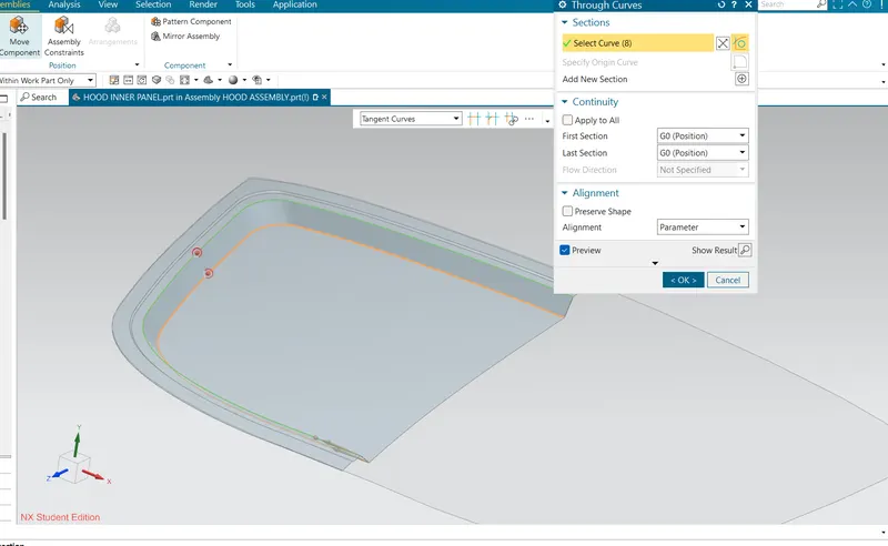
19. using face blend option give the blend radius to 15 mm.
Detailed report
HOOD
CAR HOOD
A car hood, also referred to as a “bonnet” in some countries, is the hinged cover that rests over the engine bay of a front-engine vehicle. The car hood protects the engine and connected parts from the elements while providing easy access for repairs and maintenance.
Car hoods are typically constructed from steel and sometimes from aluminum. Aftermarket car hoods may be constructed from various other materials, including carbon fiber, fiberglass, or dry carbon.
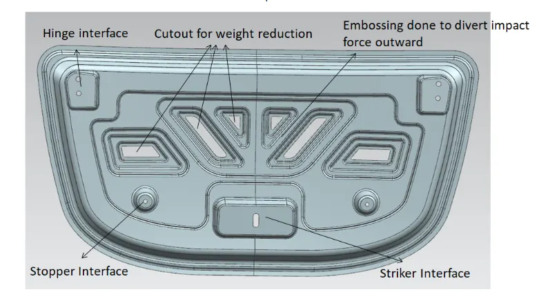
COMPONENTS-: Outer panel, inner panel, emboss, hinge assembly , letch mechanism
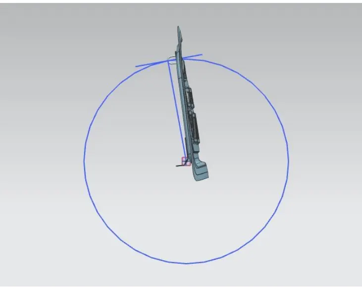
Letch trajectory
The latch trajectory is the path which the striker will follow when the hood is open/closed while pivoting on the hinge axis. The latch trajectory is taken as a circle with the hinge axis as the center of the circle. The striker is placed 90 degree such that it is tangent to the circle.
Mastic data
Sealants are materials that are for one-time use only. Mastic sealants are widely used in the automotive industry.Mastic is commonly used on construction projects as an adhesive and sealant. It is a popular choice where one surface needs to be adhered to another in a durable bond, or where the area needs to be protected.
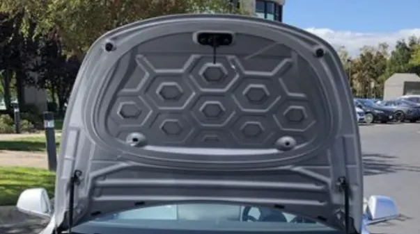
It is basically an NVH topic mastic are point/surfaces given on embosses for applying mastic sealant to joint inner panel and also give good value of NVH. One spot of mastic sealant provides strength locally at around 80 mm so we need to put these mastic points in such a way that it covers the most of the hood region except reinforcement area of latch and hinge because that alone provide good NVH so no worries there.
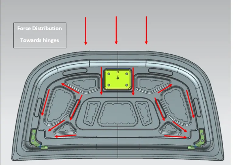
Emboss defination
Emboss has been given to create extra strength in inner panel and embosses design needs to be inspired by force dissipation phenomena like here I have made embosses in a way if any object hit from front most of the force will get dissipated by its designed towards the upper left and right corner so that less force reaches at occupant’s end.
Deep drwaing
Deep drawing is one of the most widely used processes in sheet metal forming Apart from its use in many other sectors, it is applied in the automotive industry for the manufacturing of car body parts.
The deep drawing process is a forming process which occurs under a combination of tensile and compressive conditions. A flat sheet metal blank is formed into a hollow body open on one side or a hollow body is formed into a hollow body with a smaller cross-section.
Deep drawing processes are divided into three types:
Deep drawing with tools
Deep drawing with active means
Deep drawing with active energy
In the automotive industry, deep drawing is usually carried out using rigid tools.
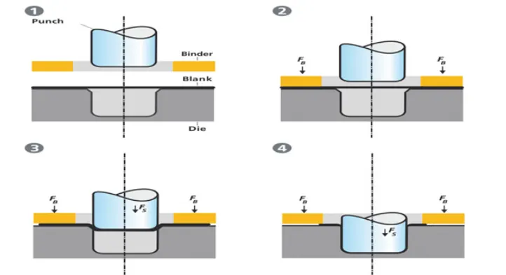
Illustration of the deep drawing process
The figure illustrates the deep drawing process. The rigid tools consist of a punch, die and binder. In deep drawing, the plate holder closes after the metal sheet blank has been inserted.
Next the sheet is clamped between the die and the binder. This process slows down the flow of the sheet while it is being drawn and thereby prevents wrinkles from forming under the binder. The punch stretches the sheet over the die radius and forms it in the die. The amount of punch force necessary for forming is thereby continually increased up to the lower dead center of the punch.
Whereas in pure deep drawing there is no reduction of sheet metal thickness, forming is achieved in stretch forming purely as a result of a decrease in sheet metal thickness. Stretch forming is extensively used for the forming of only slightly curved parts with low depth of draw (e.g. roofs, doors).
When drawing complex car body parts in practice, there is usually a combination of stretch and deep drawing involved. It is necessary that the sheet metal is stretched as well as possible without reaching the material’s limits (e.g. splits, wrinkles).
There are approximately 300 to 400 sheet metal parts which fit together to form the body of a car. In order to manufacture high quality sheet metal parts optimally for their particular use, specialized software simulates the complete deep drawing process.
Hemming
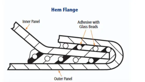
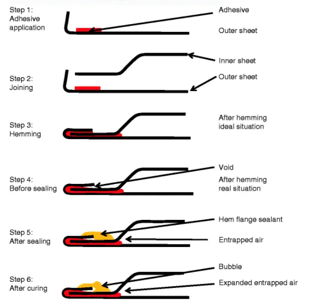
Hemming is a forming operation in which the edges of the sheet are folded or folded over another part in order to achieve a tight fit. Normally hemming operations are used to connect parts together, to improve the appearance of a part and to reinforce part edges.
In car part production, hemming is used in assembly as a secondary operation after deep drawing, trimming and flanging operations to join two sheet metal parts (outer and inner) together. Typical parts for this type of assembly are hoods, doors, trunk lids and fenders.
The accuracy of the hemming operation is very important since it affects the appearance of the surface and surface quality. Material deformations, which occur during the hemming process, can lead to dimensional variations and other defects in parts. Typical hemming defects are splits or wrinkles in the flange, material overlaps in the corner areas or material roll-in. This is why it is important to use simulation tools in order to, on the one hand, better understand the hemming process and, on the other hand, significantly reduce the number of “trial and error” loops during tryout und production.