Hood design-Week 2
AIM:=
Design Hood Outer Panel, Inner Panel and the necessary reinforcements by following the Master Section mentioned with the Design parameters explained in the videos.
Objectives:=
- Submit an ASSEMBLY of Hood Inner Panel, Outer Panel, Latch, Hinge and the Reinforcements.
A detailed report about the Hood Design which includes a detailed explanation about hood and its components, Latch Trajectory, Mastic Data, Emboss Definitions, Manufacturing process like Deep-Drawing and Hemming, and all the parameters followed in the design.
Data to be used:
Hood Thickness Information
- Outer Panel Thickness = 0.75mm
- Inner Panel Thickness = 0.75mm
- Reinforcement Thickness = 1.5mm
- HOOD DESIGN- CHALLANGE
-
INTRODUCTION
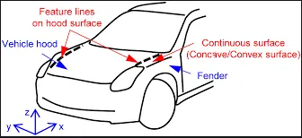
The hood or bonnet is the hinged cover over the engine of the vehicle. Hoods can open to allow access to the engine compartment, or trunk on rear-engine and some mid-engine vehicles) for maintenance and repair.
A car hood is meant to protect the performance parts of your vehicle, including the engine, while also providing easy access for repairs and maintenance. It is possible for the hood to incur damage as well. One of the most common types of damage is to the hinge, which is the device that connects the hood to the body of the vehicle. Over time, the hinge can become loose or may fall off completely. The hood is also prone to receiving scratches and dents. Although this might appear to be a minor problem, dents and scratches can lead to depreciation in the value of your vehicle. Scratches and dents can also lead to exposure to the elements that can result in rust and corrosion. This can be a serious problem that can ultimately expose the engine in your car to snow, sunlight, and rain. When this happens, it can impact the performance of your car's engine.
The first important criteria for designing the hood is to set an opening angle till which the hood panel can be opened. This opening angle is different for different countries which largely depends on the average height of a person in that particular country.
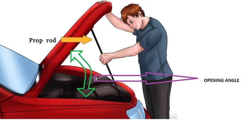
- The movement of the hood can be controlled by either one of them:
1. Gas stay
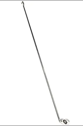
2. Support rod
1. Gas Stay
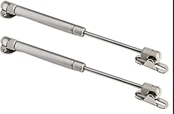
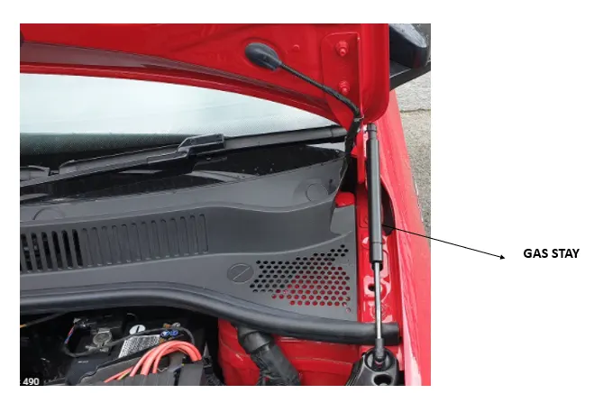
- A gas stay is a type of spring that, unlike a typical mechanical spring that relies on elastic deformation, uses compressed gas contained within an enclosed cylinder sealed by a sliding piston to pneumatically store potential energy and withstand external force applied parallel to the direction of the piston shaft.
2. Support Rod
- This is the most commonly used rod for opening and closing the hood at a certain angel. One end of the rod is hinged to the engine compartment and the other end is set free so that it can be locked to the hood inner panel when the hood is opened. This is usually used when the weight of the bonnet is small.
- It is very important to consider that the support rod should not collide inside the engine compartment.
Padestrian safety NCAP (New car assessment program) standards:
Globally, various NCAPs are present that carry on the pedestrian safety tests on new vehicles and rate them accordingly.
1. Head Impact
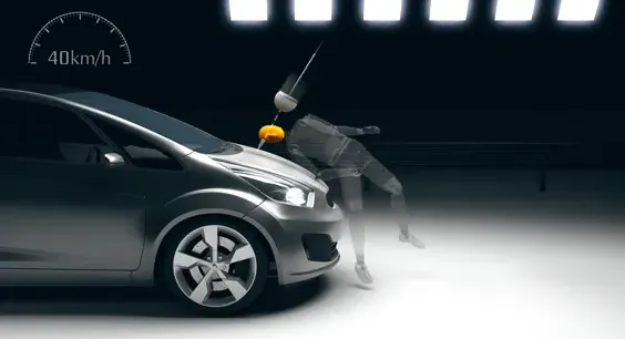
This test is carried out for a vehicle speed of 40 km/h. To have an estimate of the potential head injury in the fateful event of a vehicle striking an adult or a child, a head form impactor is used in a series of impact tests and the impact sites are then assessed for and rated accordingly.
This test will give essential information about the deformation clearance, energy-absorbing structures and deployable protection systems such as pop-up bonnets and external airbags in a new vehicle.
2. Upper Leg Impact
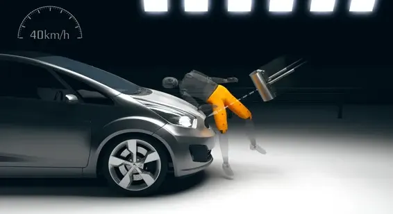
The facility carries out the test at the vehicle speed of 40 km/h. An adult upper leg form impactor is used in a series of impact tests and then the impact sites are assessed. The protection is then rated as good, adequate, marginal, weak or poor. The test procedure allows to check the energy-absorbing capacity of the structures of a vehicle and also check whether the geometry of the vehicle allows mitigation of injuries.
3. Lower Leg impact
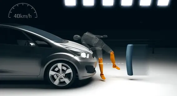
Euro NCAP carries the test at the same speed standard as the above ones. It uses an adult leg impactor and a series of tests are carried out. Impact sites are then assessed and the protection rating is offered.
4. AEB Pedestrian
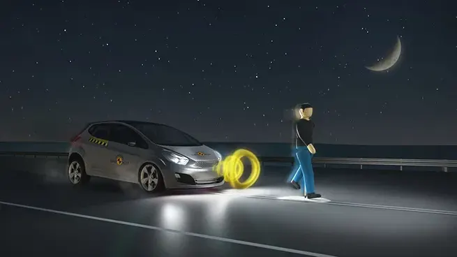
For this test, the NCAP uses a specially-designed pedestrian form which has articulated limbs to replicate the walking motion of a human. Cars are assessed on the basis of how forgiving the front-end design is in case of impact. AEB pedestrian tech may not be able to completely avoid a collision in some cases. The tests are done in the day as well as night to ensure vulnerable road users are protected all the time.
5. AEB Cyclist
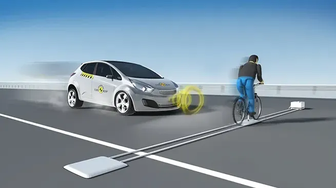
For this test, Euro NCAP uses a specially designed cyclist form which will replicate the actual cyclist on the road. Euro NCAP offers the highest rating if the collision is completely avoided. The vehicle is also awarded if the speed is reduced as any reduction in speed of impact can significantly reduce the injury to the vulnerable user.
In order to measure the potential head and leg injuries in the front portion of the car illustration of crash mitigation tests is designed below:
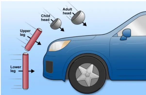
- The European New Car Assessment Programme (Euro NCAP) is a European car safety performance assessment program which has developed test specifications & rating systems for assessing pedestrian injuries during impacts with the front of vehicles such test include a series of tests using impacts designed to bio-mimic a collision at speed of 40 km/h.
- They describe a situation in which a pedestrian is situated laterally & a car first hits one of his legs. Test are conducted on the leg, upper leg & most importantly the head, as head trauma is most commonly responsible for casualties.
- So to avoid severe injuries to the head, the high impact area for adults & children are subjected to less thickness. Also no reinforcement should be provided in that area as during head collision, the hood will absrob the head impact energy leading to collapse of the hood & thus protecting severe head injury.
- Another important criteria for the hood design is the protection of the occupants inside the car during front collision. The design of the hood should be in a such a way that the during the collision, the force should travel in the upward direction through the embosses & directed towards the body of car. Thus protecting the occupants inside.
Following parts are using in hood assembly for this report,
- Hood outer panel
- Hood inner panel
- Hinge assembly
- Striker assembly
Hood thickness-
- Outer panel thickness= 0.75 mm
- Inner panel thickness= 0.75 mm
- Reinforcement thickness= 1.5 mm
Inner Panel-
- In the inner panel only we can research & implement the safety of pedestrians & as well as the driver. In this panel only we can attach the reinforcement, embossed, mastic points etc.
- It is an object of the present invention to provide a hood inner panel capable of reduction of a reaction force of the hood inner panel even if a level of deformation of a hood of a vehicle increases, & ensuring a sufficient energy absorption capacity.
-
Sheet metal embossing is a stamping process for producing raised or sunken designs or relief in sheet metal. This process can be made by means of matched male and female roller dies, or by passing sheet or a strip of metal between rolls of the desired pattern. It is often combined with foil stamping to create a shiny, 3D effect.
The metal sheet embossing operation is commonly accomplished with a combination of heat and pressure on the sheet metal, depending on what type of embossing is required. Theoretically, with any of these procedures, the metal thickness is changed in its composition.
Metal sheet is drawn through the male and female roller dies, producing a pattern or design on the metal sheet. Depending on the roller dies used, different patterns can be produced on the metal sheet. The pressure and a combination of heat actually "irons" while raising the level of the image higher than the substrate to make it smooth. The term "impressing" refers to an image lowered into the surface of a material, in distinction to an image raised out of the surface of a material.
In most of the pressure embossing operation machines, the upper roll blocks are stationary, while the bottom roll blocks are movable. The pressure with which the bottom roll is raised is referred to as the tonnage capacity.
-
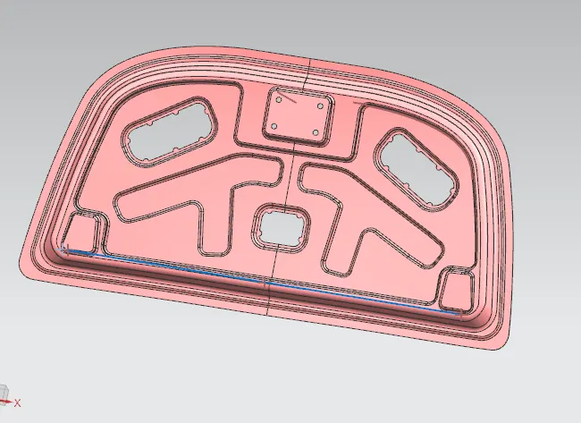
The above image shows the embosses that were designed on the hood inner panel.
The sheet was trimmed in the middle portions of the embosses to improve the strength of the hood inner panel.
To attach the hood inner panel with the hood outer panel mastic sealer will be used, in the automotive industry the most important criteria while making any product is that the aesthetic part of the vehicle which is visible to the naked eye should not have any sort of irregularities of damages, considering this important factor mastic sealer will be used to attach both the panels.
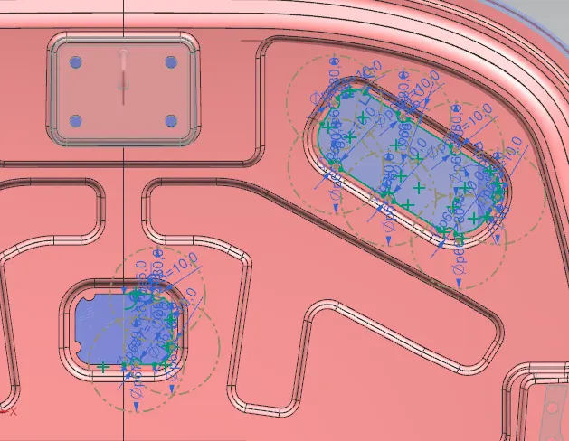
The mastic sealant is droped through a machine on the mastic points and then the sealant gets spread around 80 mm in diameter when pressed. In this way the outer hood panel is attached with the inner hood panel.
The above video shows how the mastic sealer is dropped on the hood panel.
The assembly of the hood inner and outer panel is shown below:
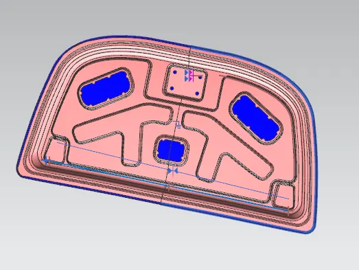
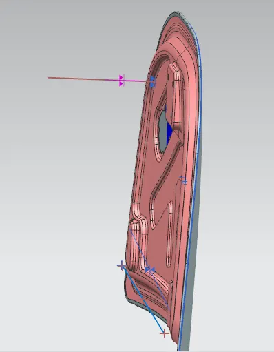
-
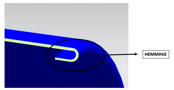
Both of them are attached together with the help of hemming operation which is performed on the edges of the hood outer panel.
Outer Panel-
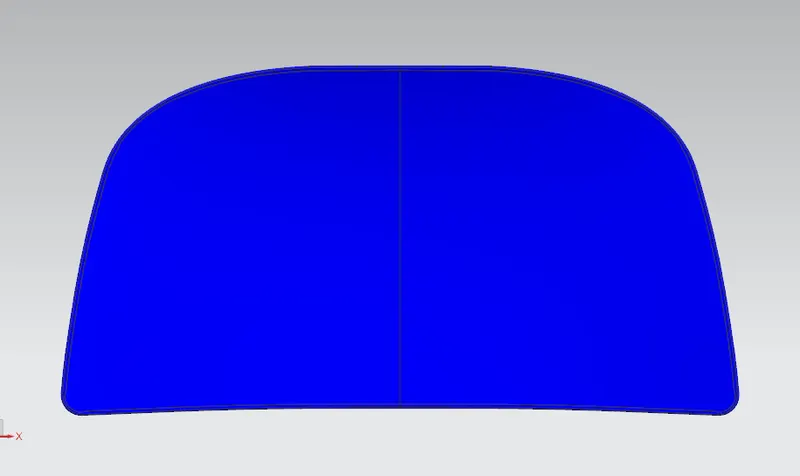
We can also call it as cover of inner panel. It is the part, which gives luxurious look to the hood or bonnet. Outer & inner panel can not join by any welding process like spot welding or rivet, which spoil the outer look of a car. The outer panel is generally extracted model from the prototype design.

-
Detailed view of the hemming cross section at the edges is shown below:
Hinge Assembly-
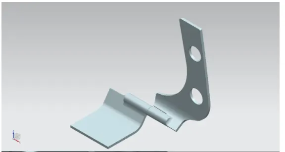
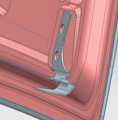
Hinge is a component that fixes the hood to the fenders of the car. The latch must be fixed perpendicular to the hinge axis so that the hood opens or closes properly.
Procedure to place latch at proper position
- The latch should be placed at appropriate position so that it does not become a obstacle while the hood is opened and closed. For this purpose it should be placed perpendicular to the hook.
- To achieve the above condition a line will be made using the axis of the hinges on the opposite ends. About the mid point of this line a datum plane will be made and then a sketch will be on this datum plane.
- Inside the sketch a circle will be made which will indicate the trajectory of the opening and closing of the hood and then a line will be made which will exactly position the latch at appropriate position.
- A tangent line will be made on the circle which will touch with the previous line.
- Another straight line will be sketched on the latch which would be perpendicular to the latch.
- Now both the straight lines will be coincided with each other using the align feature in the assembly workbench. By doing this the latch will get arrested perpendicularly and will follow the the circular patch so that the hood can be easily opened and closed.
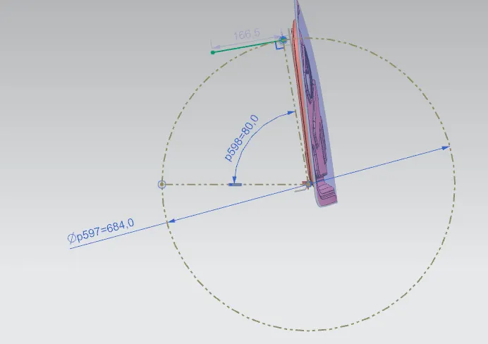
The above image shows the procedures performed to place the latch at appropriate position.
Reinforcements for latch and hinges
The material that strengthen the existing material when adding to it are called reinforced material. As the latch and the hinges will be placed on the embosses so that strength at these position will be less and that portion can get easily damaged due to movements.
In order to provide strength at these places a 1.5 mm thickness reinforcements will be placed. Reinforcement will be a metal part spot welded into the emboss of the hinge and the striker. It can't be seen from the outside as it will be welded in the back portion of the hood inner panel.
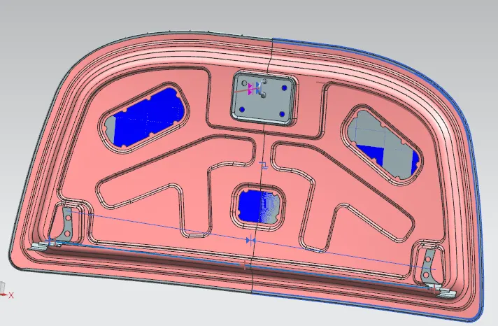
The above image shows the latch and the hinge reinforcements that were used in the above project.
Manufacturing process involved in making different features of the sheetmetal
1. Deep Drawing
The deep drawing process is a forming process which occurs under a combination of tensile and compressive conditions. A flat sheet metal blank is formed into a hollow body open on one side or a hollow body is formed into a hollow body with a smaller cross-section.
Deep drawing processes are divided into three types:
- Deep drawing with tools
- Deep drawing with active means
- Deep drawing with active energy
In the automotive industry, deep drawing is usually carried out using rigid tools.
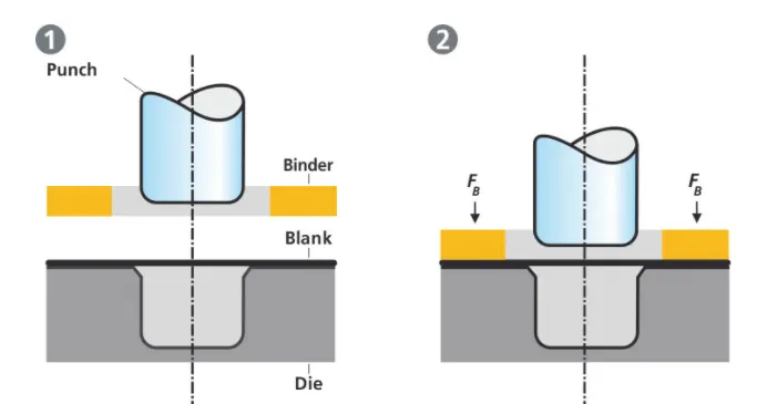
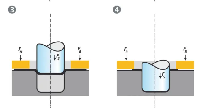
- The deep drawing operations is shown above
The rigid tools consist of a punch, die and binder. In deep drawing, the plate holder closes after the metal sheet blank has been inserted.
- Next the sheet is clamped between the die and the binder. This process slows down the flow of the sheet while it is being drawn and thereby prevents wrinkles from forming under the binder. The punch stretches the sheet over the die radius and forms it in the die. The amount of punch force necessary for forming is thereby continually increased up to the lower dead centre of the punch.
Whereas in pure deep drawing there is no reduction of sheet metal thickness, forming is achieved in stretch forming purely as a result of a decrease in sheet metal thickness. Stretch forming is extensively used for the forming of only slightly curved parts with low depth of draw (e.g. roofs, doors).
- When drawing complex car body parts in practice, there is usually a combination of stretch and deep drawing involved. It is necessary that the sheet metal is stretched as well as possible without reaching the material’s limits (e.g. splits, wrinkles).
2. Hemming
- Hemming is a forming operation in which the edges of the sheet are folded or folded over another part in order to achieve a tight fit. Normally hemming operations are used to connect parts together, to improve the appearance of a part and to reinforce part edges.
- In car part production, hemming is used in assembly as a secondary operation after deep drawing, trimming and flanging operations to join two sheet metal parts (outer and inner) together. Typical parts for this type of assembly are hoods, doors, trunk lids and fenders.
There are various types of hemming operations:
- Conventional die hemming
- Roll hemming
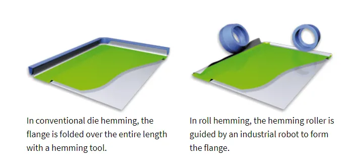
Conventional die hemming
- Conventional die hemming is suitable for mass production. In die hemming, the flange is folded over the entire length with a hemming tool. Normally the actual hemming is a result of a forming operation in which the flange is formed with a hemming tool after the drawing and trimming operations have been completed. The formed flange is then hemmed in several process steps. These steps include, for example, the pre-hemming and final hemming depending on the respective opening angle of the flange. Production plants for conventional die hemming are very expensive, but the cycle times are very low.
Roll hemming
- Roll hemming is carried out incrementally with a hemming roller. An industrial robot guides the hemming roller and forms the flange. Roll hemming operation can also be divided into several pre-hemming and final hemming process steps. Roll hemming is very flexible to use and tool costs are significantly lower as compared to those of conventional die hemming. However, the cycle times are much higher since the hemming is realized using a hemming roller which follows a defined path.
CONCLUSION
- The complete assembly of the hood outer and hood inner panel was designed as per requirement.
- The latch and the hinges were also placed at appropriate position by following a latch trajectory strategy.
_________________=:THANK YOU:=__________________________