Hood design-Week 2
INTRODUCTION -
The hood or bonnet is the hinged cover over the engine of motor vehicles. Hoods can open to allow access to the engine compartment (or trunk on rear-engine and some mid-engine vehicles) for maintenance and repair. In design perspective hood should meet some specific conditions like pedestrian safety, hood head zone for the lock striker, force distribution when subjected to frontal collision (occupant safety), manufacturability etc.
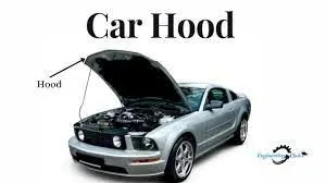
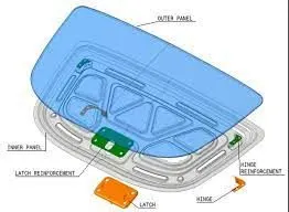
A typical hood assembly consist of hood outer panel, inner panel, latch and striker, hinge, hood stay. Hood stay is an apparatus for supporting the engine hood of a moto vehicle in its open position. The purpose of opening the engine hood is for inspecting engine room, replenishing cooling water and engine oil, changing parts and making repairs etc. Common types of hood stays are Support Rod and Gas Stay. Support rods are manually operated and they are cost effective and simple to design whereas gas stays require no man power but they are costly. Hood are typically made out of the same material as the rest of the bodywork. This may include steel and aluminium. Deep drawing, hemming, blanking and piercing are the common sheet metal operations that are used in manufacturing hoods in automotive industries.
COMPONENTS -
1. HOOD OUTER PANEL -
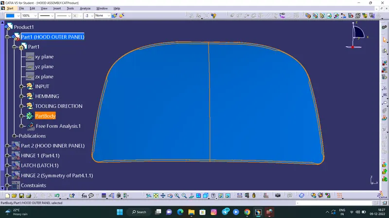
Outer panels are the aesthetic elements of a car. It is the styling team who provides the skin for the outer panel. The shape, position and size of the hood should satisfy the safety norms. So while designing the hood we should give more importance to pedestrian safety. The outer panel is attached to the inner panel by hemming. So, it is necessary to provide required hemming flange and reliefs for the hemming operation. We also provide mastic sealants between outer panel and inner panel to reduce vibration.
2. HOOD INNER PANEL -
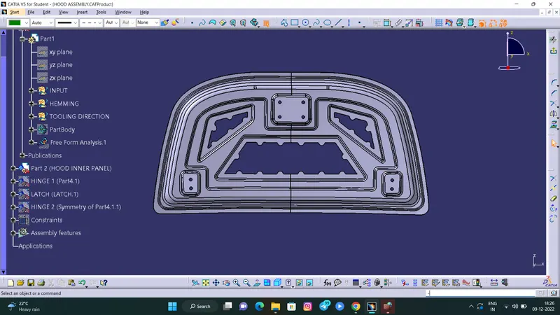
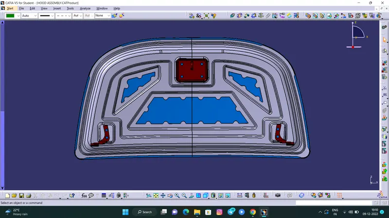
Inner panel is the part that gives strength and rigidity to the outer panel. The master section represents the initial emboss shape and size. Then we provide the emboss for the latch and hinge elements after fixing the location.
3. REINFORCEMENT -
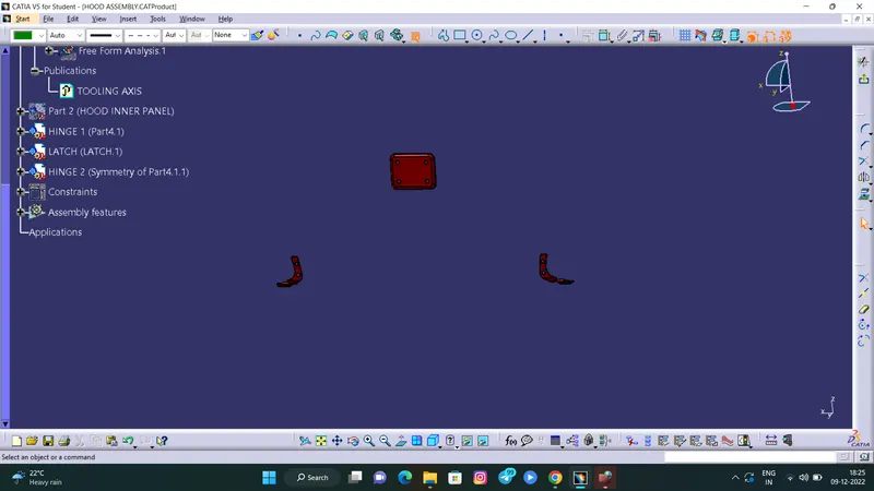
Reinforcements are provided according to the design requirements. Mainly it is provided at the hinge and latch regions to improve the strength locally. Usually thickness of reinforcements will be higher than that of the inner panels and the value varies according to cost and requirement. According to the design requirement here it is given 1.5mm thickness to both hinge and latch reinforcements.
4. LATCH TRAJECTORY -
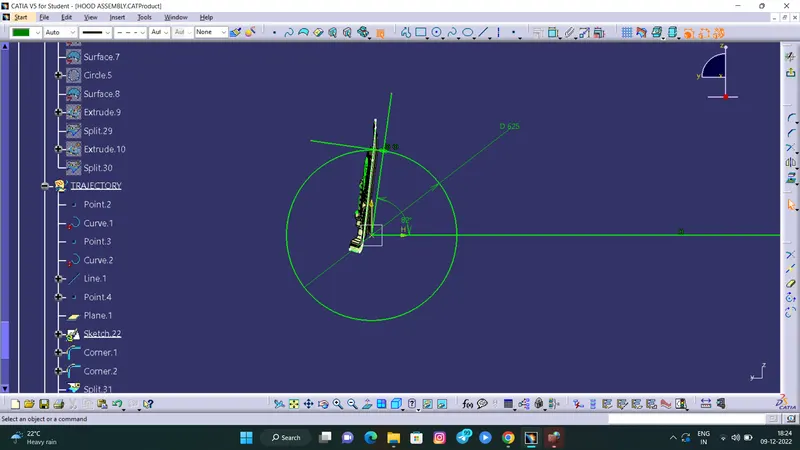
Latch trajectory is given by the circle drawn from the hinge axis point. Hinge axis point is the centre point of the hinge axis. First, we can fix either the latch or the hinge. If we have fixed the hinge position then we should plot the Trajectory circle for the latch. For proper mating condition the striker axis through the tip of the striker should be tangential to the latch trajectory.
5. EMBOSSES -
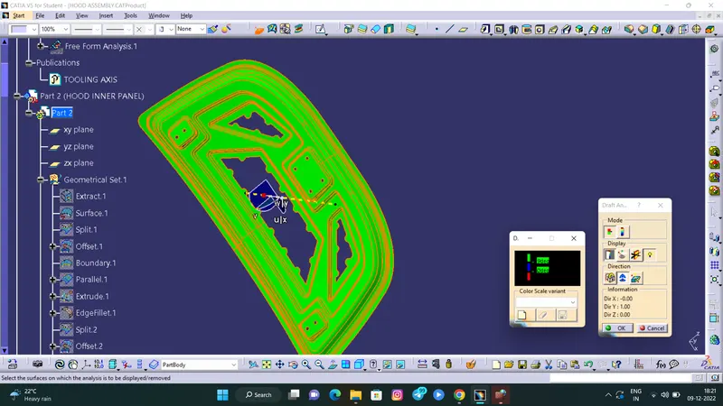
Throughout the inner panel we provide different embosses. We can increase the stiffness of the inner panel through these embosses. The shape and size of the embosses also determines the direction of the force distribution resulted from frontal collision. The force should be always distributed away from the passengers. Here in the figure the embosses are designed in such a way that the force is directed to either sides of the car.
DRAFT ANALYSIS -
1. INPUT SURFACE DRAFT ANALYSIS -
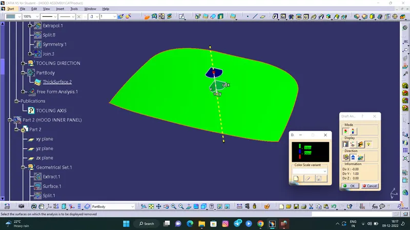
2. OUTER PANEL DRAFT ANALYSIS -
ASSEMBLY -
VARIOUS VIEWS -
MANFACTURING PROCESSES -
1. DEEP DRAWING -
The deep drawing process is a forming process which occurs under a combination of tensile and compressive conditions. A flat sheet metal blank is formed into a hollow body open on one side or a hollow body is formed into a hollow body with a smaller cross-section.
Deep drawing processes are divided into three types:
- Deep drawing with tools
- Deep drawing with active means
- Deep drawing with active energy
In the automotive industry, deep drawing is usually carried out using rigid tools.
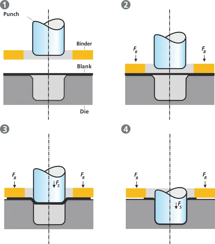
The figure illustrates the deep drawing process. The rigid tools consist of a punch, die and binder. In deep drawing, the plate holder closes after the metal sheet blank has been inserted.
Next the sheet is clamped between the die and the binder. This process slows down the flow of the sheet while it is being drawn and thereby prevents wrinkles from forming under the binder. The punch stretches the sheet over the die radius and forms it in the die. The amount of punch force necessary for forming is thereby continually increased up to the lower dead center of the punch.
Whereas in pure deep drawing there is no reduction of sheet metal thickness, forming is achieved in stretch forming purely as a result of a decrease in sheet metal thickness. Stretch forming is extensively used for the forming of only slightly curved parts with low depth of draw (e.g. roofs, doors).
When drawing complex car body parts in practice, there is usually a combination of stretch and deep drawing involved. It is necessary that the sheet metal is stretched as well as possible without reaching the material’s limits (e.g. splits, wrinkles).
There are approximately 300 to 400 sheet metal parts which fit together to form the body of a car. In order to manufacture high quality sheet metal parts optimally for their particular use, specialized software simulates the complete deep drawing process.
2. HEMMING -
Hemming in sheet metal operations refers to the bending of sheet metal edge onto itself. It is very similar to edge stitching in clothes. Similar to how an edge stitch strengthens the edge and makes it more durable, a hem imparts strength to the metal edge and improves its appearance. The edge of one part may also be folded onto another part to create a joint.
Hemming is usually done in two stages. The first stage creates an acute bend using acute tooling (V die) followed by a flattening of the return flange using a flattening die.
A complete list of hemming benefits on a sheet metal product is as follows:
-
Hems strengthen the sheet metal edge
-
They improve the surface appearance and surface quality
-
They hide defects such as rough edges and burrs
-
They can connect parts
-
They make the edges safer to handle
The different sheet metal hems based on the hem shape are as follows:
-
Flat or closed hem
-
Open hem
-
Teardrop hem
-
Rope hem
-
Rolled hem
Flat or closed hem
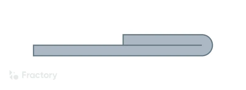
In a flat or closed hem, the part of the edge that bends sits completely flush over the rest of the metal sheet. The angle between the returning flange and the sheet metal is 180 degrees. The inside radius is zero and thus, there is no gap between the returning flange and the metal sheet.
Closed hems require a lot more power and tonnage from the presses than open or teardrop hems and it is also not advised for metal sheets that are over 2-3mm in thickness since the sheets are likely to fracture.
Open hem
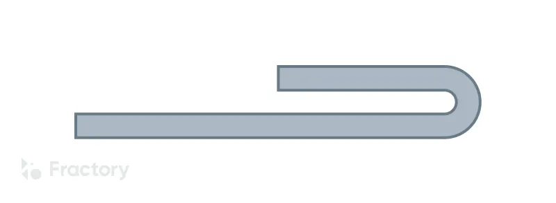
In an open hem, the returning flange is folded over the sheet metal but there remains an air pocket between the two. The bend angle in this hem type is also 180 degrees.
Teardrop hem
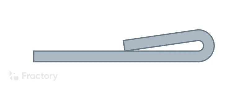
In a teardrop hem, the returning flange is bent beyond 180 degrees. The resulting shape resembles a teardrop.
It is perfect for materials that do not have the required ductility to provide closed hems. Teardrop hems are used for fragile materials such as aluminium.
Rope hem
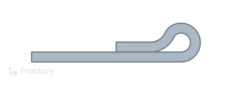
A rope hem has a returning flange at a bent of more than 180 degrees. Once the hem achieves the shape of an open hem, the returning flange is pressed onto the part surface through a flattening die.
The edge is bent in shape similar to an open hem and then the second piece to be connected is inserted into the gap between the metal sheet and the returning flange. Further pressing takes place making the second parts sit flush between the metal sheet and the returning flange and create a joint.
Rolled hem
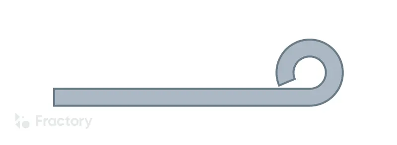
In a rolled hem, the bent portion of the sheet metal is tucked back into itself. This creates smooth round edges all around for holding the part from the hemmed edges. This process is also commonly referred to as curling.