Gearbox Sloshing using a UDF
GEARBOX SLOSHING
INTRODUCTION
Dynamic meshing involves conditions where the cell boundaries move relative to each other within a geometry.
In this case, two gears will be revolving and hence to study any associated effects, while a mesh will be created, during the simulation the parameters and characteristics of the mesh keep changing and deforming with respect to time.
The Dynamic mesh option can be enabled in Ansys fluent.
Examples – The expanding and contracting of an artery wall, piston moving inside a cylinder, flap deflection in an aircraft wing.
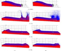
Fluid sloshing involves the motion of fluid inside another object (container). This motion is oscillatory. Depending on the motion of the container, the sloshing could be simple or harmless such as planar or translational sloshing, or it could be completely chaotic leading to negative situations.
Negative sloshing would involve the effect of earthquakes on the sea levels, or in chaotic fluid flow inside a tanker containing liquid. The dynamic effects acting on the free surface of fluids are usually studied in fluid sloshing as these can adversely affect the container the fluid is present in. Tanks and trucks containing petrol or any other flammable liquid are hazardous as fluid sloshing can be at large levels during high speed motion of the containers.
OBJECTIVES
In this study, the lubrication effects of fluid flow (N-heptane, Engine oil) inside a Gear Box are studied and compared at different levels of immersion.
Common errors such as floating point errors and negative cell volume were encountered and this study will provide explanations to how these issues were overcome.
The entire project, from pre to post processing is done using Ansys Fluent.
MODELLING APPROACH
Geometry procedure
Step 1. A 3D model of a Gearbox is imported into Ansys fluent space claim
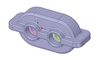
Step 2. Using volume extract, the fluid volume is first extracted
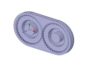
Step 3. Using split body, the gear box was divided into half.
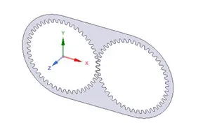
Step 4. A 2D Gearbox region was selected so that the fluid flow could be visualized and studied.
Meshing approach
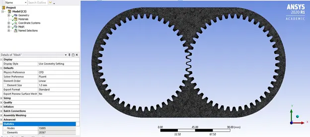
A mesh of element size 1 mm, all triangles method is used.
Total number of elements = 28367
Capture proximity: yes
PROCESSING
Using Ansys fluent, the following cases were simulated:
Case 1
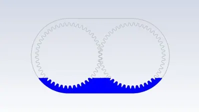
1.0: 20% Immersion n-heptane
1.1: 30% Immersion n –heptane
Case 2
2.0: 20% immersion engine oil
3.0: 30% immersion engine oil
Solver: Pressure based solver
Gravity: -9.81 m/s^2 in y direction
VOLUME OF FLUID Multiphase model was turned ON, IMPLICIT FORMULATION
Turbulence model: K epsilon realizable, Standard
Using the ADAPT feature, 20 and 30 percent regions were marked
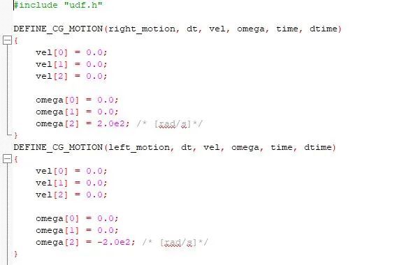
A user defined function (UDF) was loaded and built to attain the gear rotations of the left and right gears.
Using the dynamic mesh option, left_motion and right_motion were respectively assigned to the left and right gears.
Solution initialization HYBRID
Using Patch, heavier fluid (N-heptane/ Engine oil) assigned to immersion region with a value of 1
Air is the other fluid present
After running a baseline simulation, the following two errors were encountered:
- Negative cell volume detected
- Floating point error
These were fixed by making the following changes:
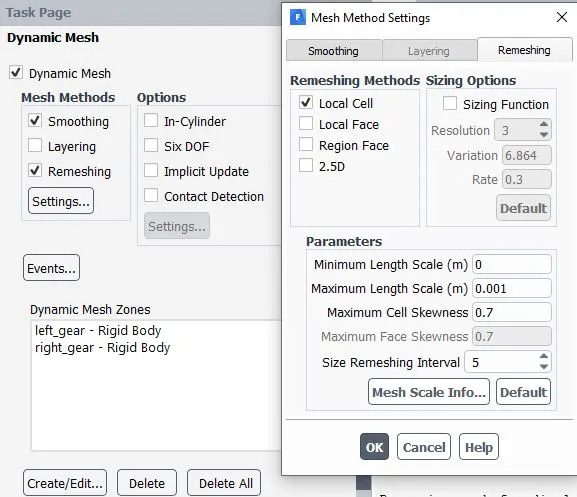
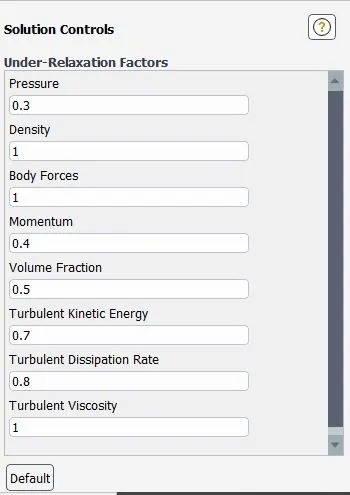
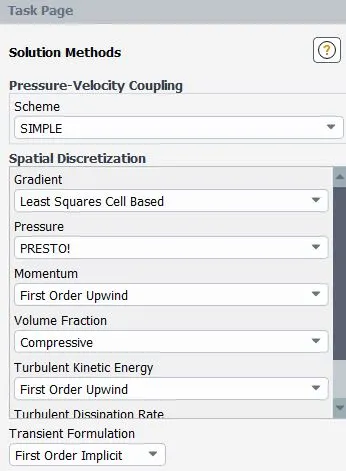
Case 1: n-heptane
1.0 20% Immersion
2.0 30% Immersion
Case 2: engine-oil
2.0 20% Immersion
2.1 30% Immersion
INFERENCES
- In the case of N-heptane, poor lubrication is seen as there is not much thickness of the lubricant at the gear meshing region
- Also, the lubricant adhering to the rest of the teeth is less while using N-heptane
- While using Engine oil however, better results are visible. A thicker coating is present for the gear at both the meshing interface and during general meshing
REFERENCES
Recent advances in liquid sloshing advances by R. A. Ibrahim and V. N. Pilipchuk T. Ikeda
Ansys Fluent documentation