Gear-Box Simulations
Part-1:
Aim: To perform and Analyze the simulations on the gearbox sloshing effect and compare the results among all the four cases.
Objective: To solve the following Four Cases:
1. 20% Immersion, Fluid (Engine oil).
2. 30% Immersion, Fluid (Engine oil).
3. 20% Immersion, Fluid (n-heptane-liquid(c7h16)).
4. 30% Immersion, Fluid (n-heptane-liquid(c7h16)).
Gearbox:
The term “gearbox” is one of those terms, oftentimes used interchangeably with gearhead or gear reducer, even though they sometimes refer to slightly different physical arrangements of the gears.
The most basic definition of a gearbox is that it is a contained gear train, or a mechanical unit or component consisting of a series of integrated gears within a housing. In fact, the name itself defines what it is a box containing gears. In the most basic sense, a gearbox functions like any system of gears; it alters torque and speed between a driving device like a motor and a load.
The gears inside of a gearbox can be any one of a number of types from bevel gears and spiral bevel gears to wormgears and others such as planetary gears. The gears are mounted on shafts, which are supported by and rotate via rolling element bearings. The gearbox is a mechanical method of transferring energy from one device to another and is used to increase torque while reducing speed.
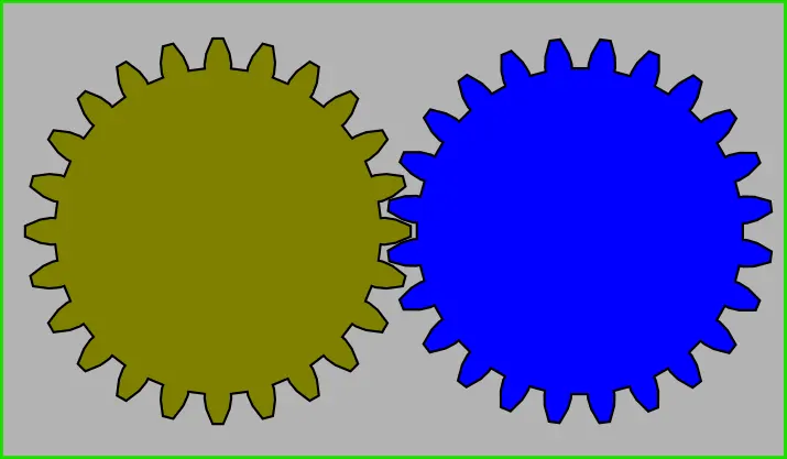
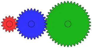
Gearboxes are used in many applications including machine tools, industrial equipment, conveyors, and really any rotary motion power transmission application that requires changes to torque and speed requirements.
In Fluid Dynamics, Sloshing refers to the movement of liquid inside another object, which is in undergoing motion.
Lubrication:
Lubrication is the process or technique of using a lubricant to reduce friction and wear & tear in contact between two surfaces.
Lubricants can be solids (such as Molybdenum disulfide MoS2), solid/liquid dispersions (such as grease), liquids (such as oil or water), liquid-liquid dispersions or gases.
Fluid-lubricated systems are designed so that the applied load is partially or completely carried by hydrodynamic or hydrostatic pressure, which reduces solid body interactions (and consequently friction and wear). Depending on the degree of surface separation, different lubrication regimes can also be distinguished.
Adequate lubrication allows smooth, continuous operation of machine elements, reduces the rate of wear, and prevents excessive stresses or seizures at bearings. When lubrication breaks down, components can rub destructively against each other, causing heat, local welding, destructive damage, and failure.
Methods of Lubrication:
Lubrication is essential to the proper functioning of an industrial gearbox. Adequate levels of lubrication benefit a gearbox by lubricating the teeth and removing heat generated from operations. Lubricant is also used on the various bearings inside the gearbox. Adequately lubricating these elements of the industrial gearbox will result in mechanical efficiency, reliability, low maintenance, and a long equipment life span.
- Oil drip feed lubrication: High-speed industrial gearboxes are lubricated through spray lubrication.
- Oil splash feed lubrication: Helical, spur, and bevel gearboxes are typically lubricated using splash lubrication. During splash lubrication, the gears or another component within the gearbox dip into an oil bath.
- Forced Oil-feed lubrication: It is preferred for high-speed applications, and includes methods such as oil mist, oil spray, and oil drop.
- Grease lubrication: Grease lubrication can be used for industrial gearbox systems that are open or closed, as long as they run at low speeds. The grease must have the correct viscosity with good fluidity, especially when used in an enclosed unit.
Gear-Box Sloshing Effect:
1. Geometry:
Using Visual Studio C++, Ansys Workbench is opened.
Open 64bit Command Prompt, And paste the target name of Workbench(It can be found at Properties of a Workbench) and Hit enter button.
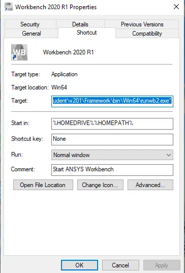
**********************************************************************
** Visual Studio 2019 Developer Command Prompt v16.7.1
** Copyright (c) 2020 Microsoft Corporation
**********************************************************************
[vcvarsall.bat] Environment initialized for: 'x64_x86'
C:Program Files (x86)Microsoft Visual Studio2019Community>"C:Program FilesANSYS IncANSYS Studentv201FrameworkbinWin64runwb2.exe"
C:Program Files (x86)Microsoft Visual Studio2019Community>
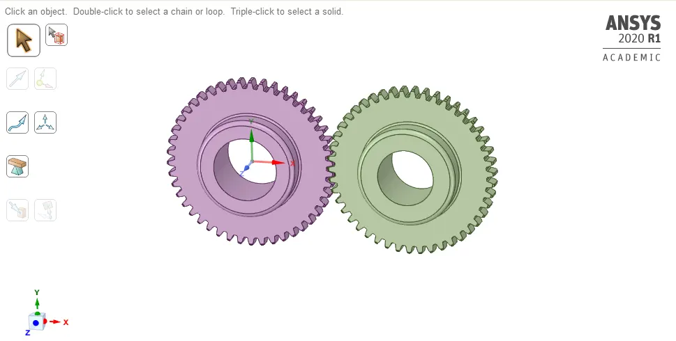
Open Spaceclaim, Import the geometry.
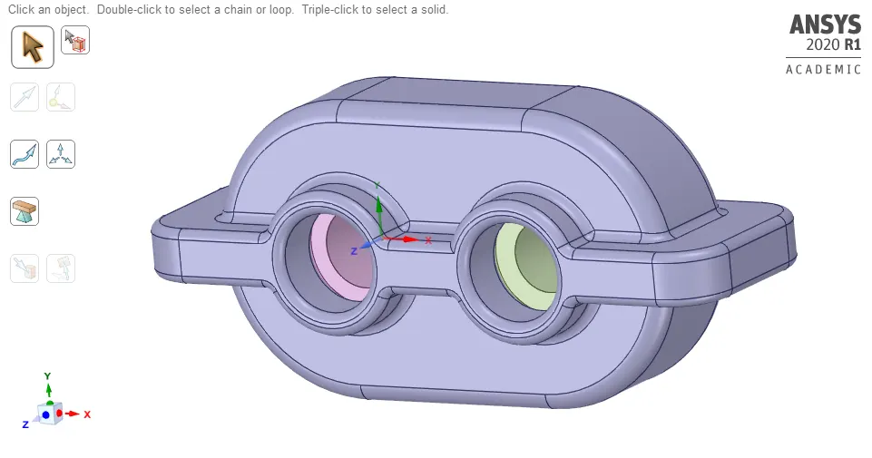
The above imported geometry consists of two spur gears enclosed by the housing.
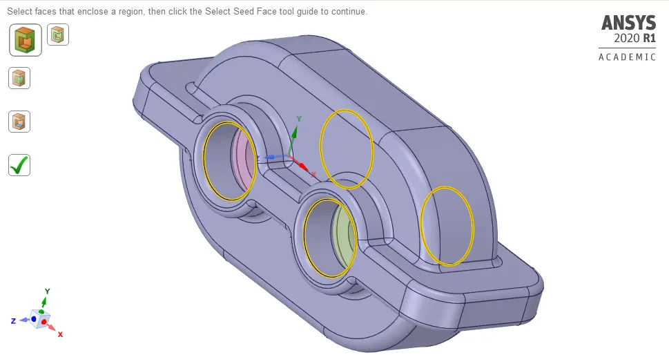
Housing:
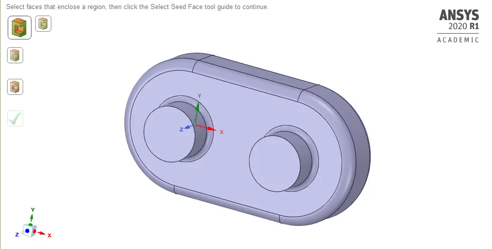
Extracted Fluid Volume:
Extracted Fluid Volume:
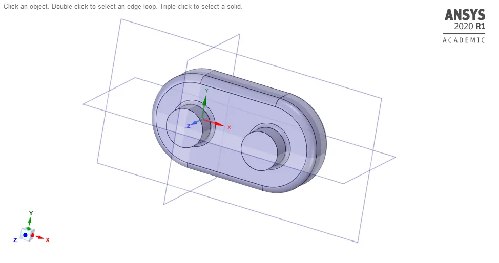
Obtaining 2D geometry:
In order to obtain the 2D geometry body is cut in half and to do that first planes are created, then selecting split body option in design. To execute a split body option first selecting the target object - in this case, the target object is 'fluid volume'. Secondly, the plane is selected in which the body is to be cut in half. Finally clicking on the unwanted region to be removed.
Splitted body:
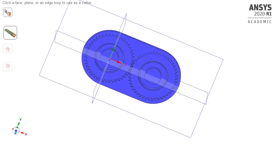
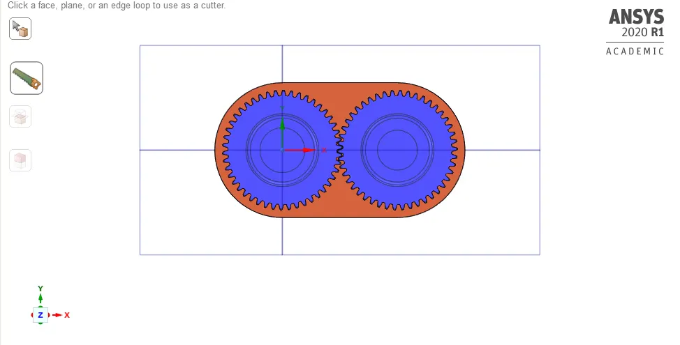
The orange-colored surface is selected and copied to create 2D geometry. The copied part is pasted in the new design while doing this care must be taken that the part is copied in "x-y plane" in order to have ease while dealing with the co-ordinates. Then the geometry is saved as '2D_gear' i.e a 2D geometry.
2D geometry:
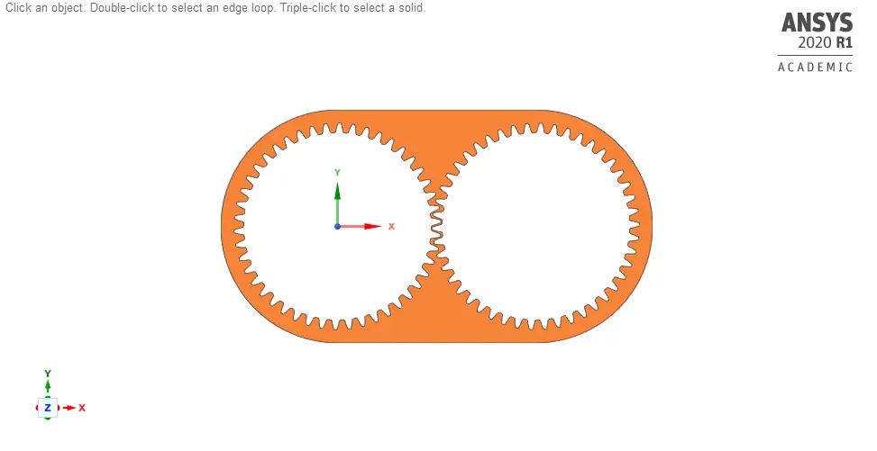
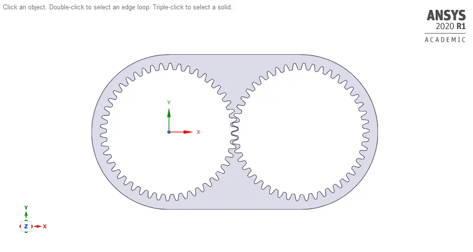
2. Meshing:
Element size - 0.7 mm
Mesh method - Inserting mesh method - All triangles method
Number of nodes - 25599
Number of elements - 47308
Capture Proximity - Yes
No. of Cells across gap - 1
Proximity Minimum size -0.3mm(Since it should be less than or equal to Element size)
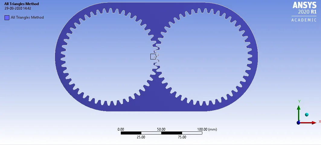
Meshing:
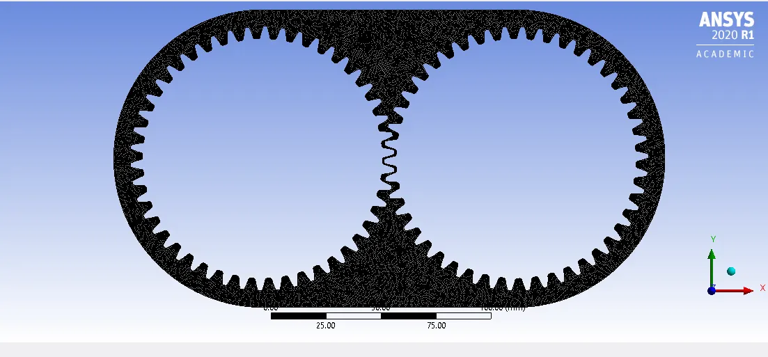
Named Selection:
By using the edge selection option all the edges of the gears individually are selected and named 'left_gear' & 'right_gear' respectively.
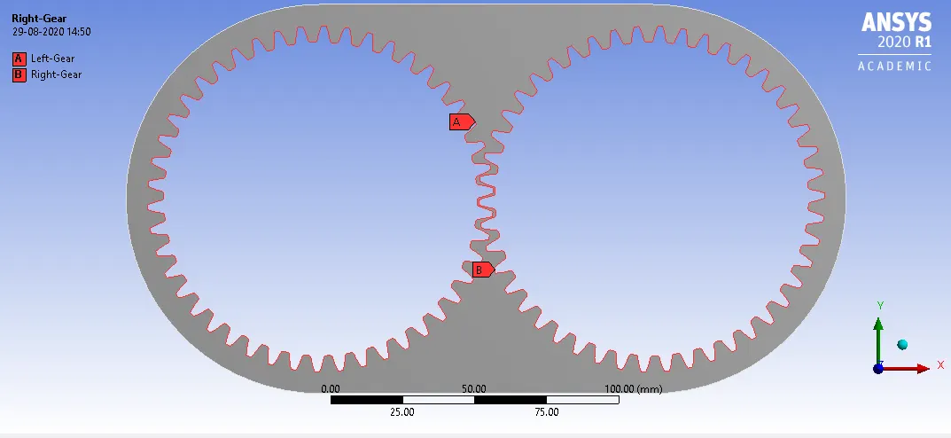
3. Setup:
Solver Type: Pressure Based.
Time: Transient.
Gravitational Acceleration is (-9.81ms2">ms2ms2) in 'y' direction.
Viscous Model: Viscous-K epsilon-"Realizable"-'Enhanced wall function`.
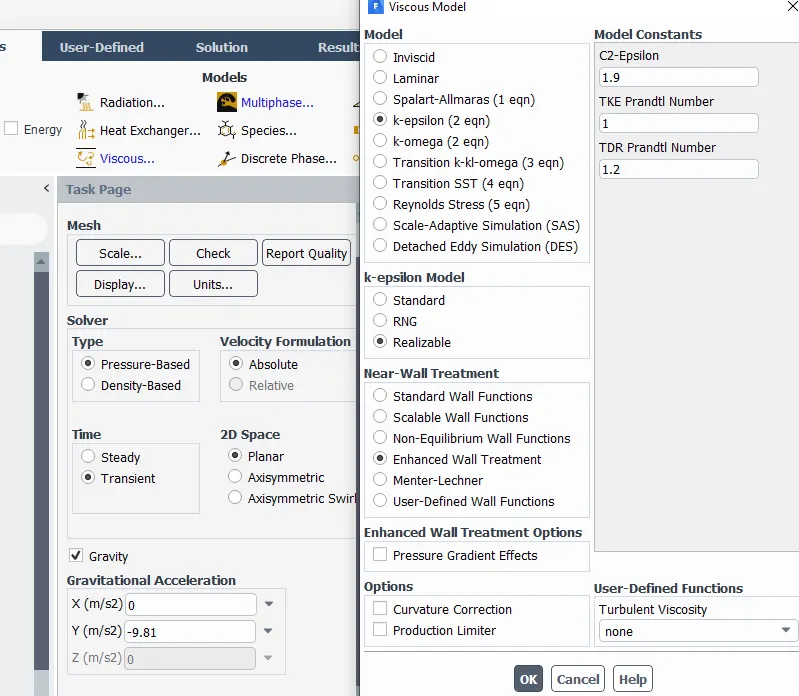
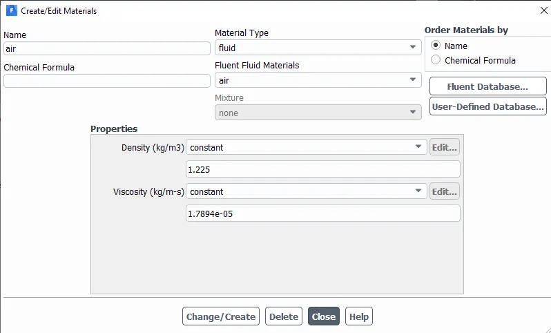
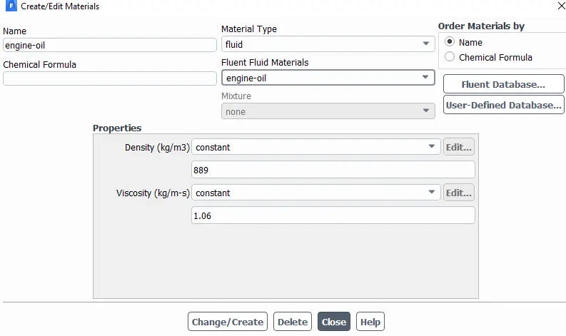
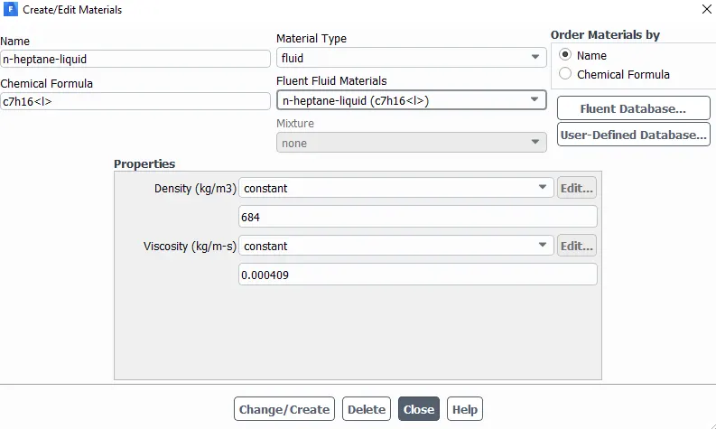
Materials:
(a).Air:
(b).Engine Oil:
(c).n-heptane (c7h16):
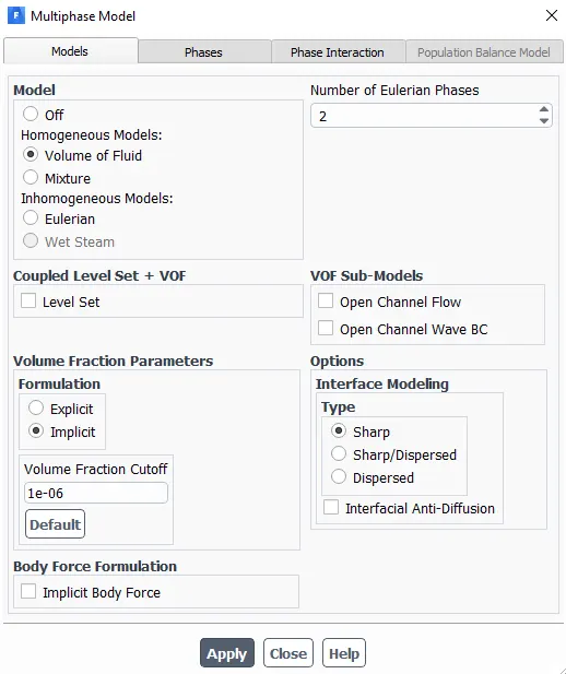
Multiphase:
Model - Volume of Fluid(VOF)
No. of Eulerian Phases - 2
Formulation - Implicit
Phases:
Primary Phase for all the 4 cases.

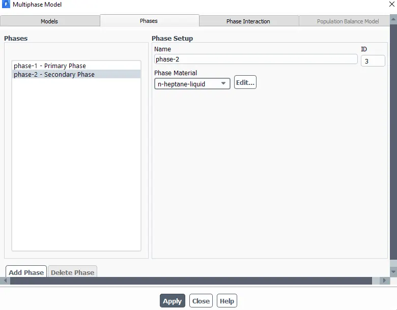
Secondary Phases:
1. For Case1 and Case2:
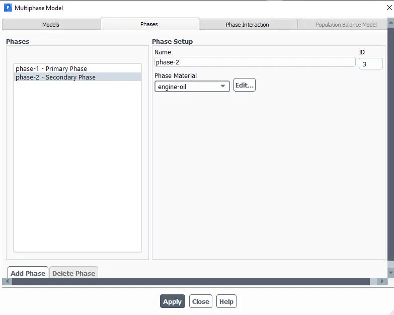
2.For Case3 and Case4:
Defining Fluid Region:
The fluid region will define where fluid has to be - it will ensure that the fluid reaches all the gears.
For this simulation of the gearbox sloshing effect, two different fluid regions are used for 4 cases.
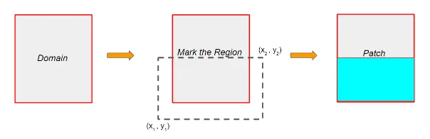
a) 20% Immersion - Lubricant occupies 20% of complete fluid geometry.
Before that, Open SpaceClaim:
Measure total height with respect to gravity acting axis:h=135mm.
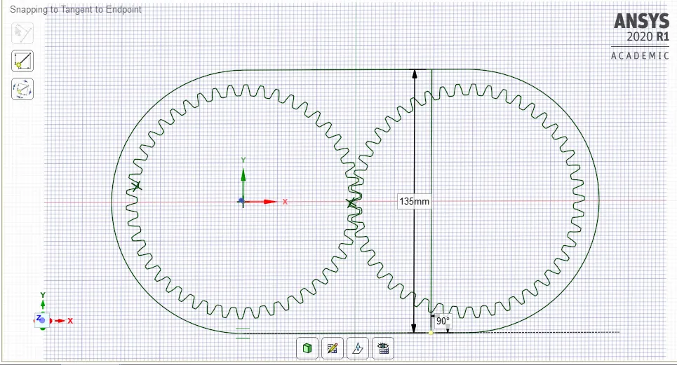
For 20%:- 0.2*h=0.2*135=27mm.
Draw a vertical line of 27mm.
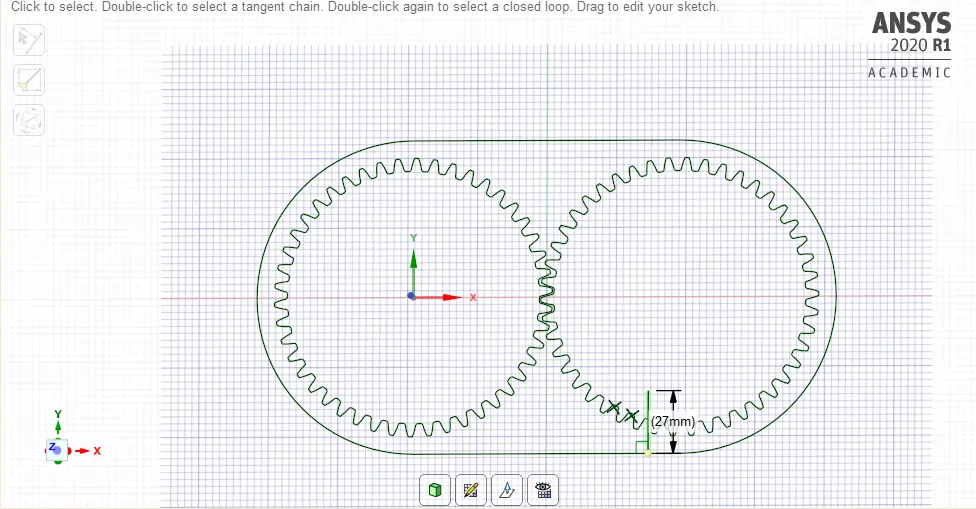
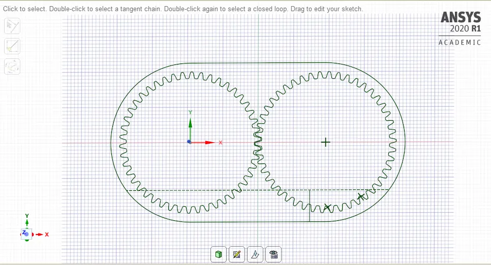
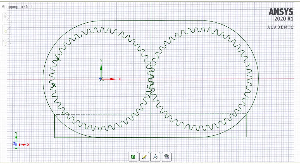
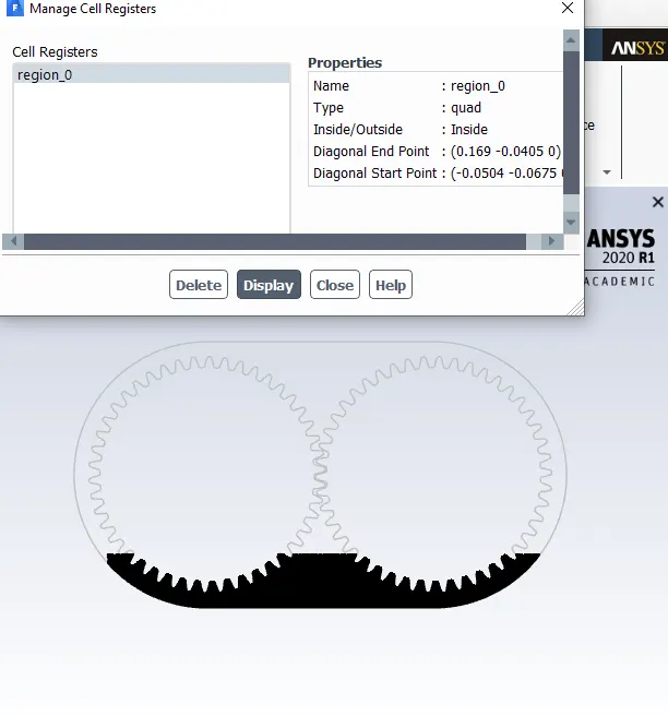
Draw a Quad:
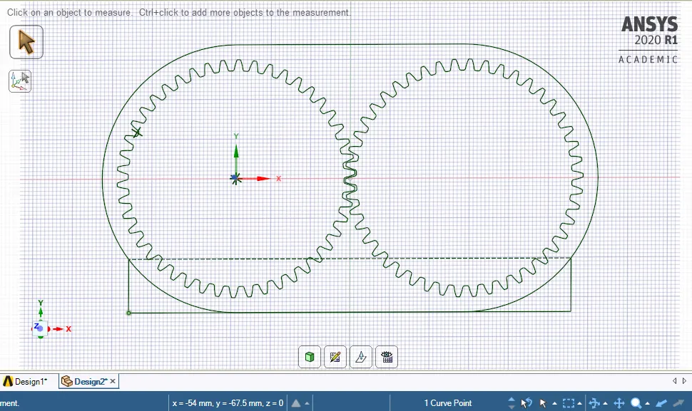
Measure at a point as mentioned above:
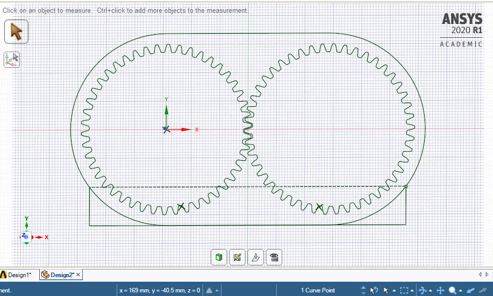
Fluent- Domain- Adopt Cells- Cell Registers- Region- Give the values
b) 30% Immersion - Lubricant occupies 30% of complete fluid geometry.
Before that, Open SpaceClaim:
Measure total height with respect to gravity acting axis:h=135mm.
For 30%:- 0.3*h=0.3*135=40.5mm.
Draw a vertical line of 40.5mm`
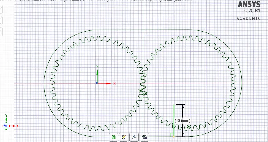
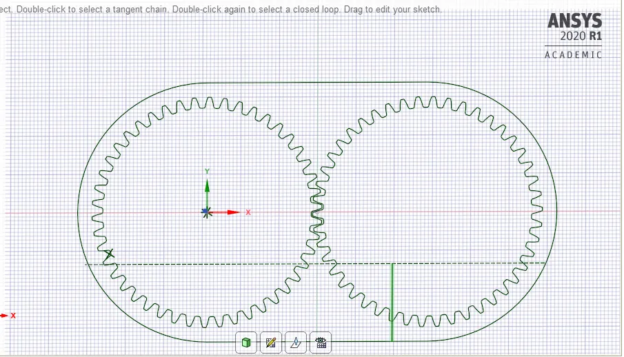
Draw a Quad:
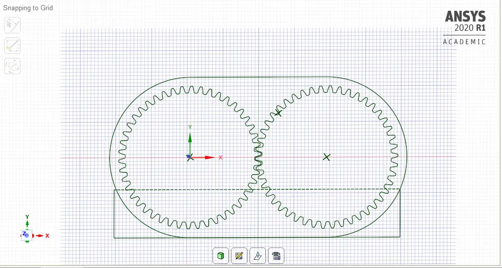
Measure at a point as mentioned above:
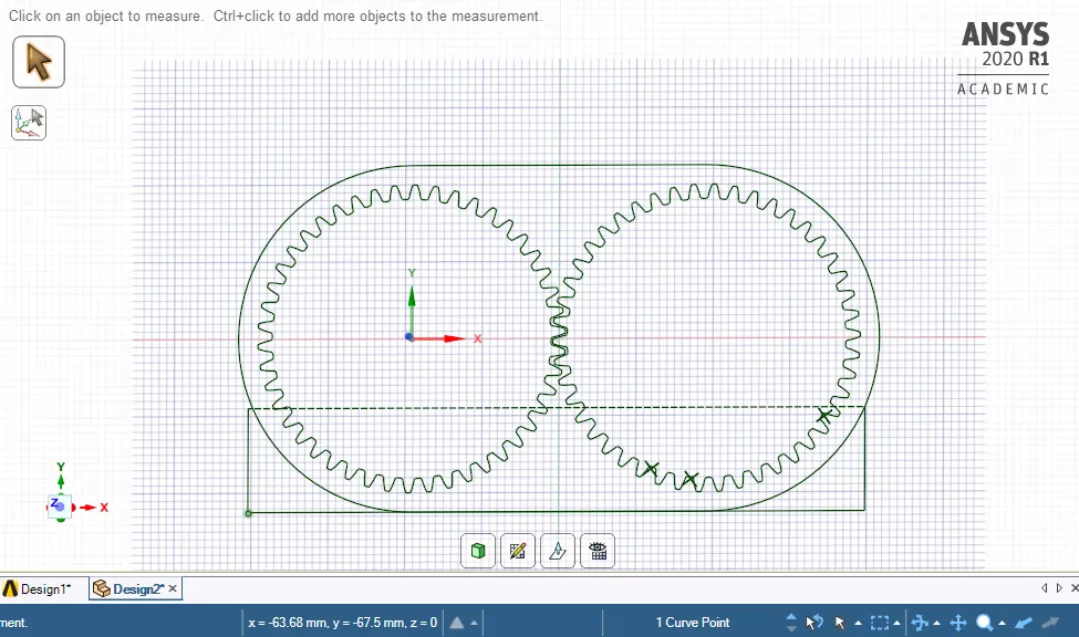
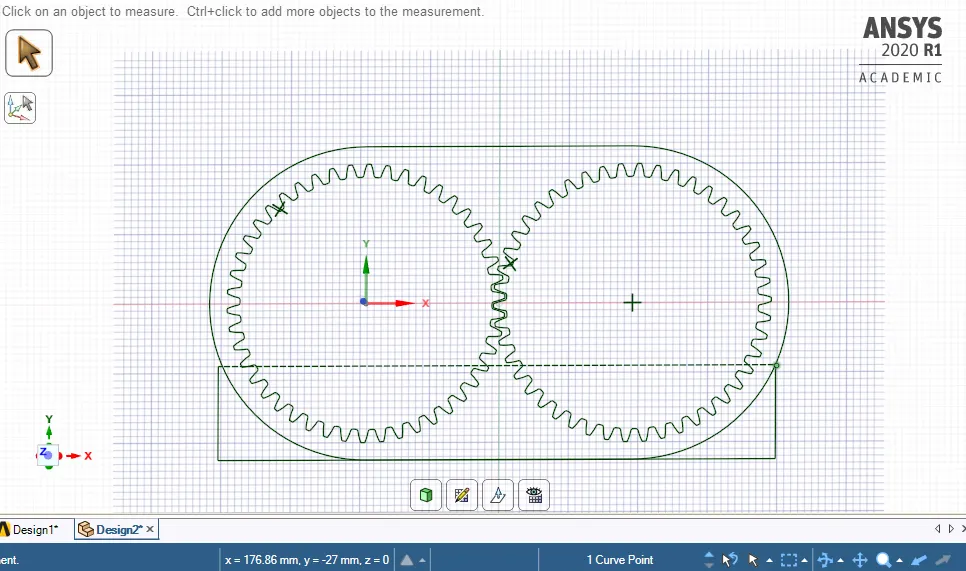
Fluent- Domain- Adopt Cells- Cell Registers- Region- Give the values
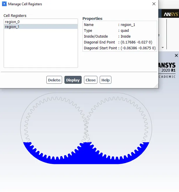
User-Defined:
Here adding the UDF file under functions and then selecting compiled and adding the file 'rate.c'
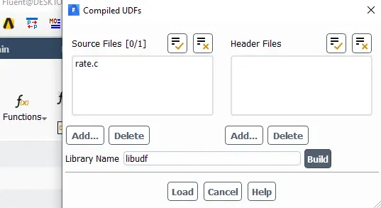
File 'rate.c':
#include "udf.h"
DEFINE_CG_MOTION(right_motion, dt, vel, omega, time, dtime)
{
vel[0] = 0.0;
vel[1] = 0.0;
vel[2] = 0.0;
omega[0] = 0.0;
omega[1] = 0.0;
omega[2] = 2.0e2; /* [rad/s]*/
}
DEFINE_CG_MOTION(left_motion, dt, vel, omega, time, dtime)
{
vel[0] = 0.0;
vel[1] = 0.0;
vel[2] = 0.0;
omega[0] = 0.0;
omega[1] = 0.0;
omega[2] = -2.0e2; /* [rad/s]*/
}
Dynamic Mesh - This helps in simulating the model flows where the shape of the domain is changing with respect to time due to motion on the domain boundaries.
For gear sloshing effect simulation - the motion of gears is defined by User-defined Function which states gears are rotating with an angular velocity of 200 rad/sec.
The left gear rotates at point (0,0) and right gear rotates at (0.115,0) meters
The dynamic mesh function works by using 3 different methods:
- Smoothing – The nodes move according to boundary motion and elements stretch out like springs to keep the nodes joined.
- Layering – The mesh moves layer by layer. (Useful in sliding mesh for less magnitude deformation)
- Remeshing – The mesh is remeshed locally in regions that do not satisfy user-specified limit on sizes and skewness.
The Smoothing spring constant is equal to 1.
The Remeshing limits require a minimum and maximum sizes of elements and their skewness limit. To calculate those limits, a theoretical deformation of an element in the worst case. The worst-case would be when the base of the triangle is fixed with 2 nodes and another node displaces totally.
As above mentioned the angular velocity is taken as 200 rad/sec
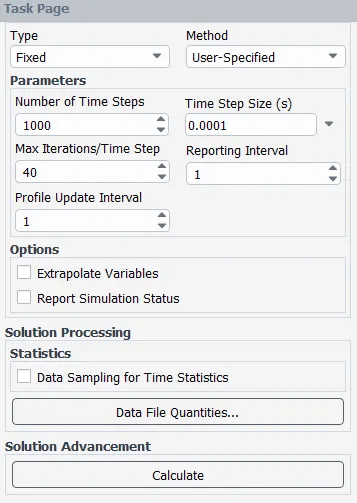
- we need to calculate the flow time for 1 rotation of the gear pair to set up the time step size and No. of time steps accordingly to achieve 2 rotations minimum.
- In industry-standard practice is usually about 5-6 rotations but considering the academic license & Computational time, we proceeded with 2 rotation for this project.
Flow time calculation to determine Time step size and No. of Time steps in Ansys fluent :
where Omega: 200 rad/s(From the UDF file)
omega = (2piN)/60
Therefore, N = 1909 Rpm.
N/60 = 1909/60 = 31.83 Rps.
This means we get 31.83 rotations per second.
So, how many seconds does it takes for 1 Rotation :
1/31.83 = 0.0314 seconds of flow time.
So for 2 Rotations we need,
2/31.83 = 0.0628 seconds of flow time.**
Determining Time step size and No. of time steps for all cases :
" Time step size * No. of Time steps = Total flow time."
we know the flow time as 0.0628 seconds,
Therefore by choosing Time step size as 0.0001, we get No of Time steps as:
No of Time steps = 0.0628/0.0001 = 628.
For the Simulation, the chosen Time step is 650 which will give results just slightly over 2 rotations for all cases.
So , Time step size = 0.0001
No. of time steps = 650
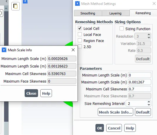
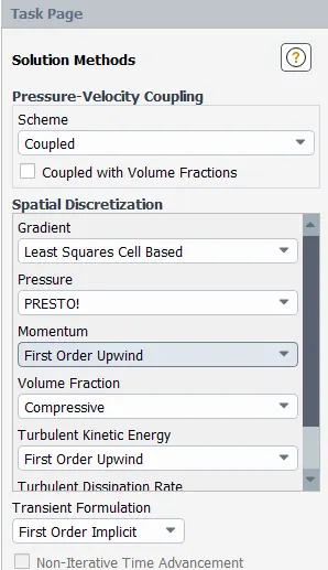
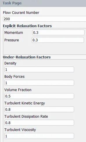
Dynamic Mesh Zone: Creating dynamic mesh zones for left and right gears in order to assign the proper motion to the respective gears by setting up UDF.
At Dynamic mesh, Create/Edit:
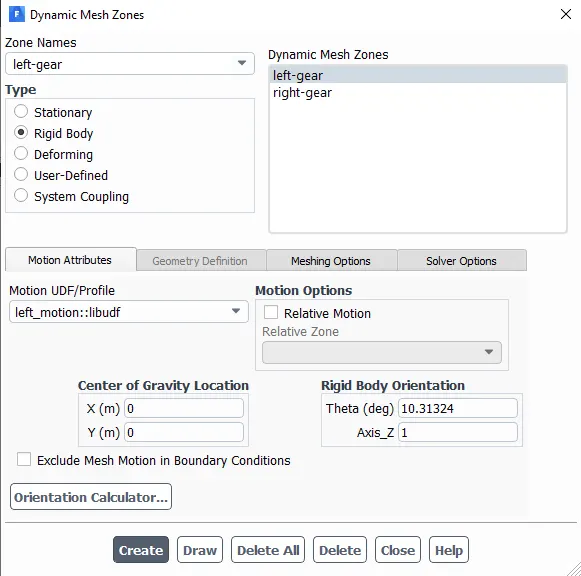
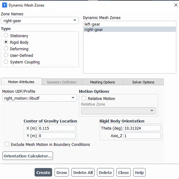
Display Zone Motion: This is used in order to preview the motion and to check whether the UDF setup correctly.
Initialization: With the above simulation setup initialization is done by the 'Hybrid Initialization Method'.
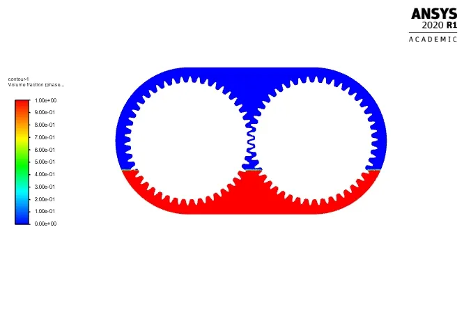
Patch - Representation of phases.
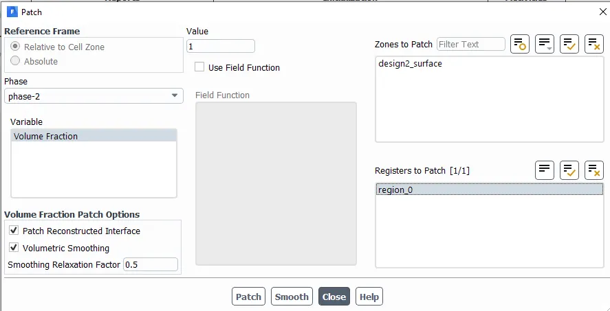
Representation of Contours:
For 20% Immersion:
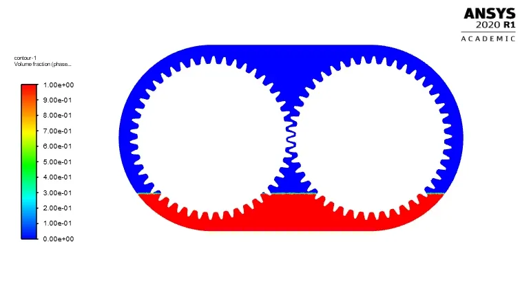
For 30% Immersion:
Run Calculation: With the above setting and Proper changes, Running all the simulation cases for the same total time.
Results for Four different cases:
Case1: 20%Immersion,Fluid-Engine oil:
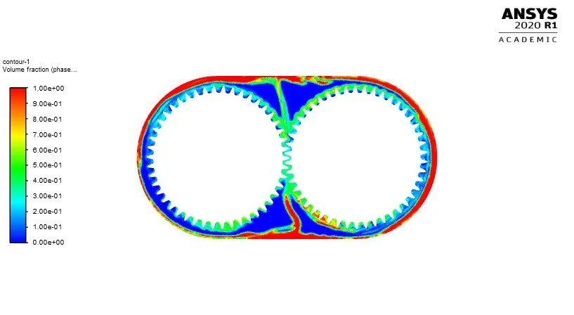
In this case, the fluid region is set up in such a way that the fluid region is filled with 20% of 'engine-oil' for lubricating inside the gearbox.
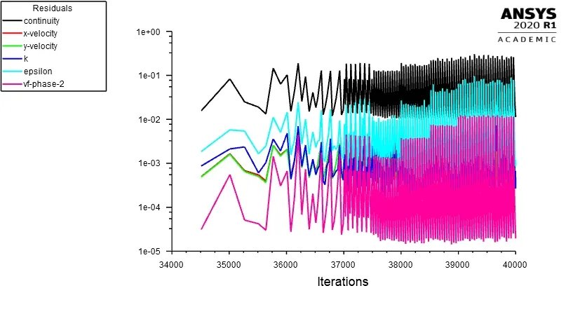
Residuals:
Contours:
Animations:
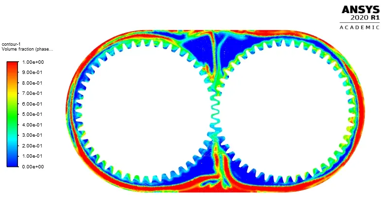
Case2: 30%Immersion, Fluid-Engine oil:
In this case, the fluid region is set up in such a way that the fluid region is filled with 30% of 'engine-oil' for lubricating inside the gearbox.
Residuals:
Contours:
Animations:
https://youtu.be/Vyy7hkBThJU
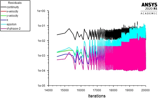
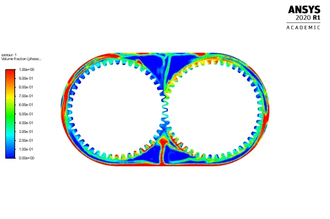
Case3: 20%Immersion, Fluid-n-heptane (c7h16):
In this case, the fluid region is set up in such a way that the fluid region is filled with 20% of 'Fluid-n-heptane (c7h16)' for lubricating inside the gearbox.
Residuals:
Contours:
Animations:
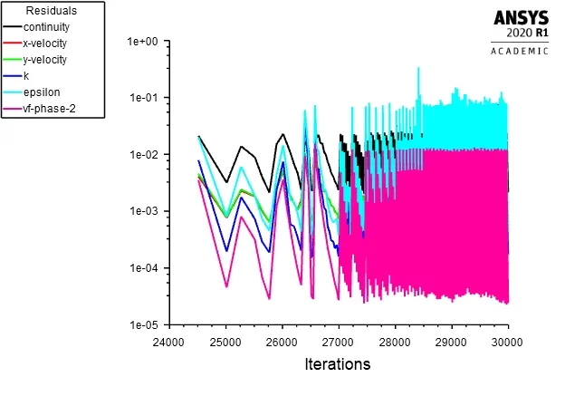
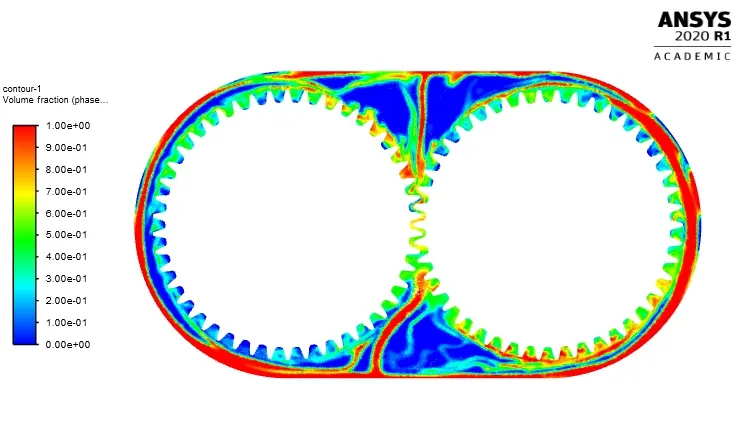
Case4: 30%Immersion, Fluid-n-heptane (c7h16):
In this case, the fluid region is set up in such a way that the fluid region is filled with 30% of 'Fluid-n-heptane (c7h16)' for lubricating inside the gearbox.
Residuals:
Contours:
Animations:
Conclusions:
*Simulation of GearBox has been performed for four different Configurations with 20% and 30 immersion with Engine oil and 20% and 30 immersion with N-Heptane(c7h16).
*It is observed that 30% of Immersion has more lubricant than 20% lubricant.
*When gear starts rotating there is enough lubrication to fill the gap between teeth, right from the first rotation of the gear in 30% immersion case. Whereas, the gears are in a loss‐of‐lubrication operating condition for a long time due to less lubricant in 20%immersion case.
*It is observed that the formation of engine oil lubricant film over a gear tooth is more stable than n-heptane as a lubricant on it.
*Engine-oil has more ability to stick to the tooth surface as compared to n-heptane-liquid this is because engine-oil has a high viscosity that results in appropriate temperature distribution.
*The higher value of engine-oil viscosity results in lower oil consumption and less wear during gear rotation.
Part-2:
1. What is Dynamic meshing? Give some other examples where dynamic meshing can be used.
>> Dynamic Mesh Module is a tool that allows the motion of parts or subparts relative to static ones, which therefore makes the fluid volume changing in the time frame. In the dynamic mesh model, the boundaries of a cell zone are allowed to move relative to other boundaries of the zone and to adjust the mesh accordingly. The boundaries can move rigidly with respect to each other (that is, linear or rotational motion), and/or deform.
The dynamic mesh model allows you to move the boundaries of a cell zone relative to other boundaries of the zone, and to adjust the mesh accordingly. The boundaries can move rigidly with respect to each other (that is, linear or rotational motion), and/or deform.
Dynamic Mesh Model is a method by which the solver(FLUENT) can be instructed to move boundaries and/or objects and to adjust the mesh accordingly.
The dynamic meshing can be used to model flows where:-
- FSI simulation blood flow pumping in the human heart.
- Fluid solid interaction of airflow around building and finding final deflection and fluctuation (two way and one-way FSI)
- Two and four-stroke internal combustion engine.
- Train movement in the tunnel by variable velocity function in an urban tunnel.
- Gearbox.
- Solid fuel combustion and modeling solid height level during burning fuel.
- Fluid solid interaction of blood flow and vessel.
- Six DOF dynamic mesh for modeling variation of location and angle of ship and boat in wavy sea situation.
- Simulation of the tidal turbine using six DOF dynamic mesh method (calculating rotation speed).
- Releasing of food box from an airplane using six DOF dynamic methods.
- The shape of the domain is changing with time due to motion on the domain boundaries.
- Simulation of globe valve movement during the time.
- Simulation of flap movement of an airplane wing.
- Modeling the underwater vehicle in Submerged and non-submerged situation.
- Automotive piston moving.
2. What is the fluid Sloshing effect? Discuss whether the sloshing effect is good or bad? Explain.
>>In fluid dynamics, slosh refers to the movement of liquid inside another object (which is, typically, also undergoing motion). However, it has become common to refer to liquid motion in a completely filled tank, i.e. without a free surface, as "fuel slosh"
Slosh is an important effect for spacecraft, ships, and some aircraft. Slosh was a factor in the Falcon 1 second test flight anomaly and has been implicated in various other spacecraft anomalies, including a near-disaster with the Near-Earth Asteroid Rendezvous (NEAR Shoemaker) satellite.
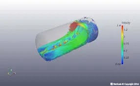

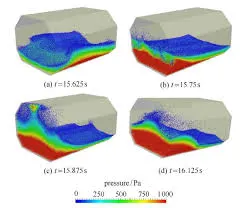
Sloshing is also a periodic motion of the free surface of the liquid in a partially filled tank or container that can be caused by several factors. It is viewed in many applications. In freely slosh it can produce forces that cause instability, rollover, and failure or damage in tank or container in some cases. Baffles used as sloshing suppression devices. The severity of sloshing and its dynamic pressure loads depend on the tank geometry, the depth of the liquid, the amplitude, and the nature of the tank motions. They also depend on the frequency of excitation over a range of frequencies close to the natural frequency of the fluid.
Sloshing of liquid in the storage tank may result in negative effects such as deformation and failure of tank walls due to impact. If an open tank is subjected to ground motions, sloshing may lead to liquid spillage. Therefore, sufficient clearance needs to provide between the free surface and top of the tank or roof must be provided.
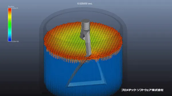
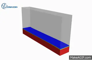
For example propellant slosh in spacecraft tanks and rockets (especially upper stages), and the free surface effect (cargo slosh) in ships and trucks transporting liquids (for example oil and gasoline). However, it has become common to refer to liquid motion in a completely filled tank, i.e. without a free surface, as "fuel slosh".
Such motion is characterized by "inertial waves" and can be an important effect in spinning spacecraft dynamics. Extensive mathematical and empirical relationships have been derived to describe liquid slosh. These types of analyses are typically undertaken using computational fluid dynamics and finite element methods to solve the fluid-structure interaction problem, especially if the solid container is flexible. Relevant fluid dynamics non-dimensional parameters include the Bond number, the Weber number, and the Reynolds number.
3. What is the use of UDF?
>>A user-defined function, or UDF, is a function that you program that can be dynamically loaded with the ANSYS FLUENT solver to enhance the standard features of the code. For example, we can use a UDF to define our own boundary conditions, material properties, and source terms for flow regime, as well as specify customized model parameters (e.g., DPM, multiphase models), initialize a solution, or enhance postprocessing.
A user-defined function (UDF) is a common fixture in programming languages and the main tool of programmers for creating applications with reusable code. Since programs are mostly composed of code that comes from the programmer, or in this case the user, most of it is composed of user-defined functions occasionally punctuated by built-in functions.
User-defined functions allow programmers to create their own routines and procedures that the computer can follow; it is the basic building block of any program and also very important for modularity and code reuse since a programmer could create a user-defined function which does a specific process and simply call it every time it is needed. Their syntax depends entirely on the programming language or application where they are created.
UDFs are written in the C programming language using any text editor and the source code file is saved with a .c extension (e.g., myudf.c). One source file can contain a single UDF or multiple UDFs, and we can define multiple source files.
UDFs are defined using DEFINE macros provided by ANSYS FLUENT. They are coded using additional macros and functions also supplied by ANSYS FLUENT that access ANSYS FLUENT solver data and perform other tasks.
Every UDF must contain the UDF.h file inclusion directive ( #include "udf.h") at the beginning of the source code file, which allows definitions of DEFINE macros and other ANSYS FLUENT-provided macros and functions to be included during the compilation process. Values that are passed to a solver by a UDF or returned by the solver to a UDF are specified in SI units.
4. Discuss the common errors that occurred in the simulation. A] 'Dynamic mesh failed' error. B] 'Negative cell volume detected' error.
>>A) Dynamic mesh Failed error :
Apply under-relaxation
Under-relaxation is a simple yet effective technique for updating the fields between iterations. The default way to update the field values in a new iteration would be to simply ignore the old value and replace it with the new values. The standard way to deal with this is under-relaxation and is very effective. Instead of replacing the field values with the new result, it is better to update with a weighted average between the old and the new values.
Start initializing with the values:0.7 for velocity and 0.3 for pressure and other scalar fields
If the simulation diverges, try using lower relaxation factors like 0.3 for velocity and 0.1 for pressure.
You can find these values at Fluent SetUp >> solution controls. You can see in the solution page.
Solvers
- Use coupled implicit solver if possible.
- You can choose the GAMG and smooth solver. Especially smoothSolver performs quite well when the matrices have bad conditions.
Processor
- Running in series or parallel with a single processor sometimes helps.
B] Negative cell volume detected error:
- Check all mesh quality parameters and maintain the skewness(skewness under 0.8), aspect ratio, and Orthogonal Property(More than 0.1) within the appropriate range.
- The bad mesh can lead to floating-point errors. Try to use conformal mesh because interfaces are prone to give this error.
You can find the values at Fluent Setup >> Mesh Method Controls.
References:
https://skill-lync.com/knowledgebase/how-to-overcome-floating-point-exception-error
https://skill-lync.com/knowledgebase/theory-of-dynamic-meshing-for-gearbox-sloshing-problem
https://skill-lync.com/knowledgebase/mesh-models-and-applications
https://skill-lync.com/knowledgebase/multiphase
https://skill-lync.com/knowledgebase/why-we-need-to-do-under-relaxation