Foundation Design using SAFE
Challenge-13
Foundation Design using SAFE
1. Model the isolated footing provided in week 11 challenge on SAFE. Analyze and design it to verify the size, depth and steel provided as per calculations.
Introduction :-
- Isolated footings (also known as Pad or Spread footings) are commonly used for shallow foundations in order to carry and spread concentrated loads, caused for example by columns or pillars.
- Isolated footings can consist either of reinforced or non-reinforced material.
- The categories of isolated foundation footings are the following:
1. Pad Footing
A pad or flat isolated footing is constructed by plain or reinforced concrete. Its thickness is constant and its shape can be circular, rectangular or square. It is economic and requires less excavation but its size is highly depended on the load and it is less resistant in lateral forces.
2. Sloped Footing
Sloped isolated footing requires less concrete and reinforcements bars than pad footing. It is constructed cautiously in order to maintain a 45-degree inclination from all sides. The concrete mix used must be stiff in order to avoid sustaining viscous deformation.
3. Stepped Footing
This type of footing includes the construction of a footing step by step until it reaches the desired width. This technique is mostly used in residential buildings but its utilization has been decayed over the last decades.
Aim :-
- To model the isolated footing provided in week 11 challenge on SAFE and analyze and design it to verify the size, depth and steel provided as per calculations.
Procedure :-
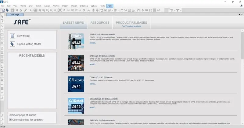
- Open SAFE 2020.

- Select New Model.
- Now, New dialogue box will open named model Initialization.
- Select Units and Codes as per your project.
- we have selected Indian codes and units as Metric SI.

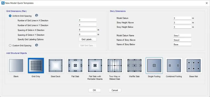
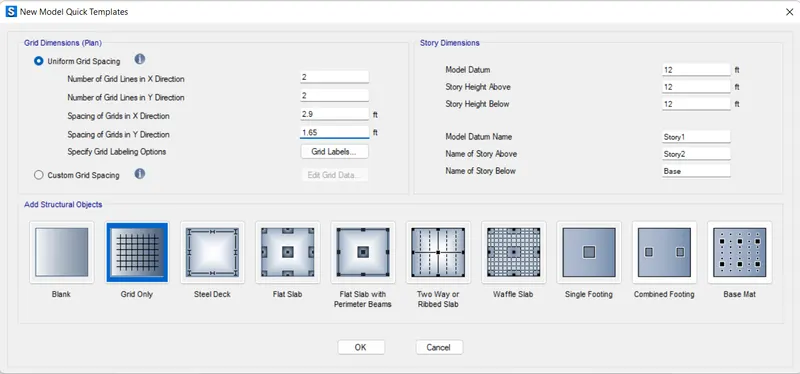
- Now select the uniform grid spacing.
- Select Single Footing.
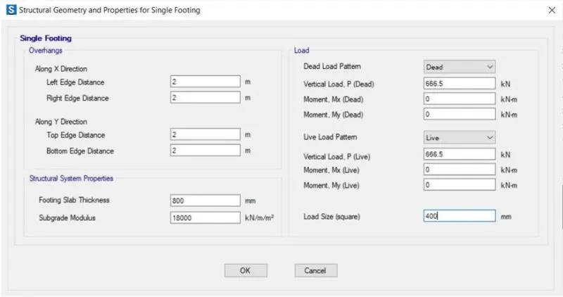
- In single footing, Insert the dead loads and live loads.
- Calculations are as per following.
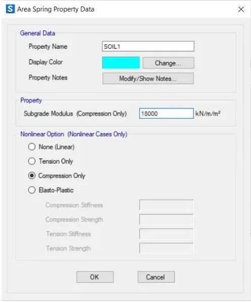
Subgrade Modulas = FOS*SBC / Max. Settlement
= ( 3*150 ) / 0.05
= 9000 KN/m^3.
The compression axial load for load combination (1.5DL + 1.5LL) is 2000KN.
Unactored Load = 2000 / 1.5
= 1333.3 KN
Dead load Breakup = 1333.3 / 2
= 666.5 KN
Live load Breakup = 1333.3 / 2
= 666.5 KN
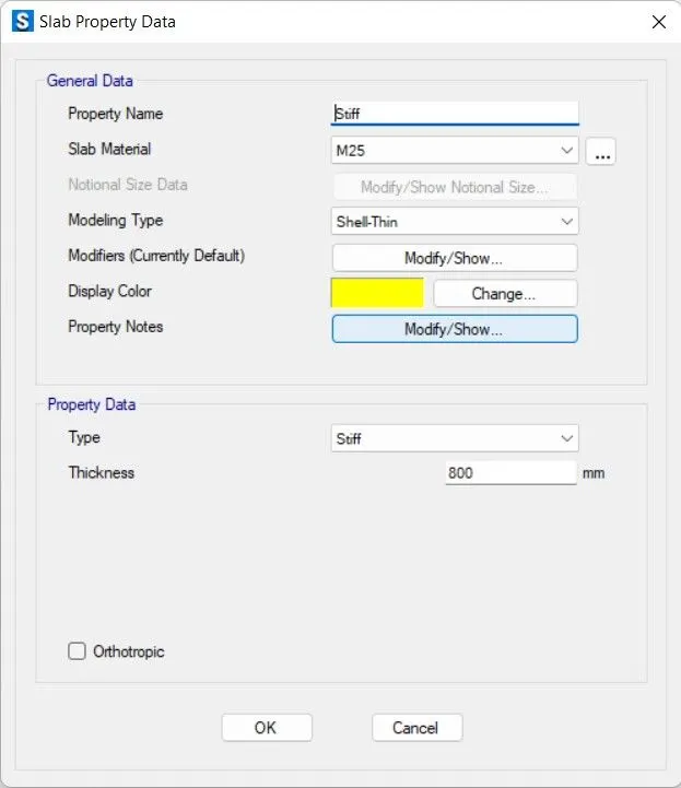
So, Footing Thickness is 800mm.
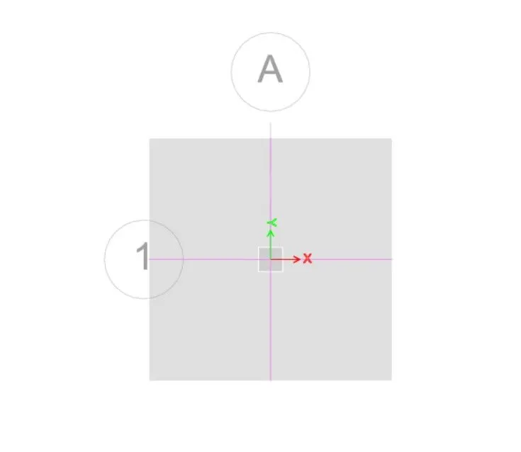
- So single Footing is successfully added.
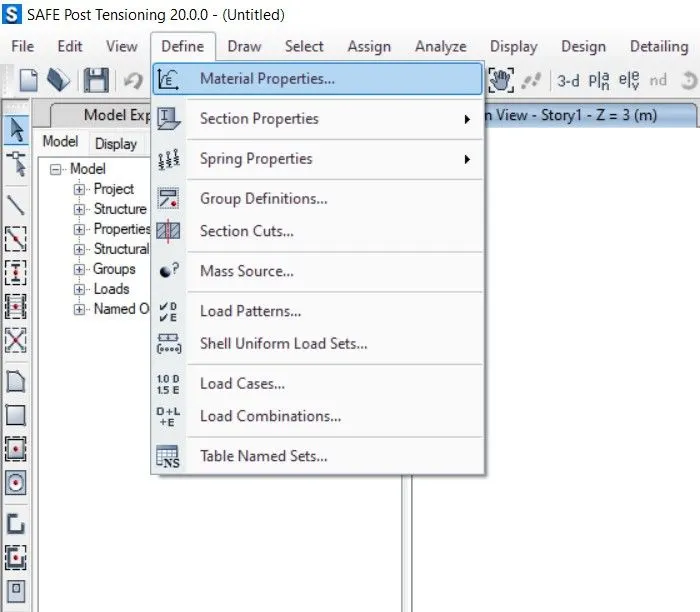
- Select Material properties under define tab.
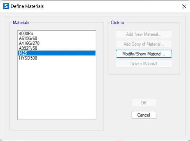
- New dialogue box will appear named Define Materials.
- Select Add new Material from the window.
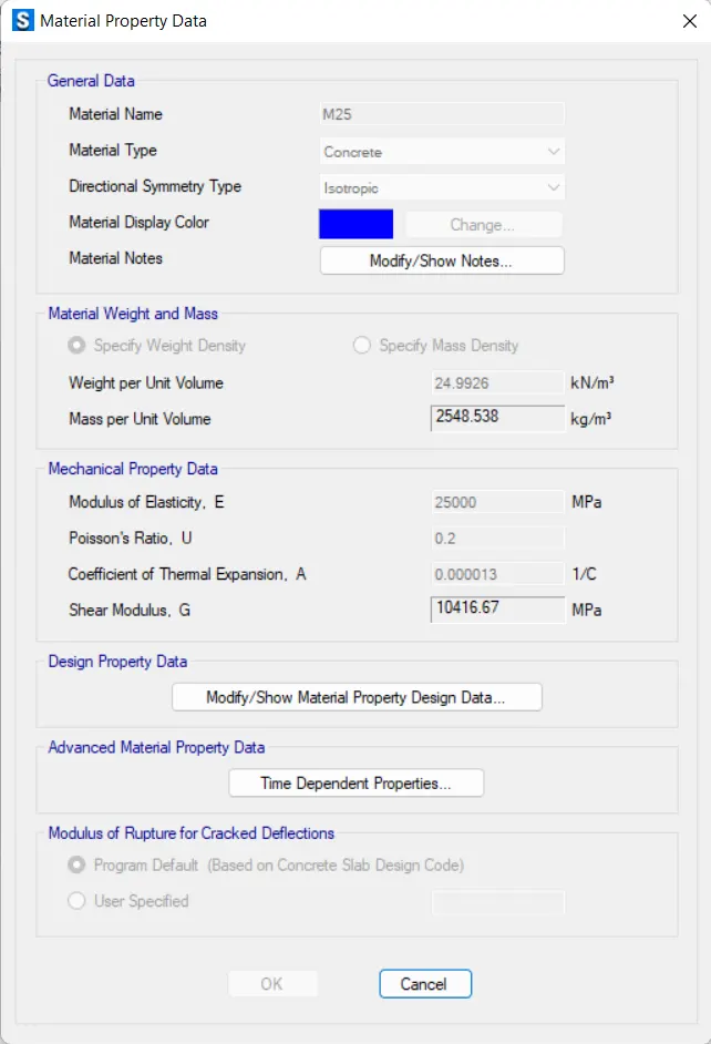
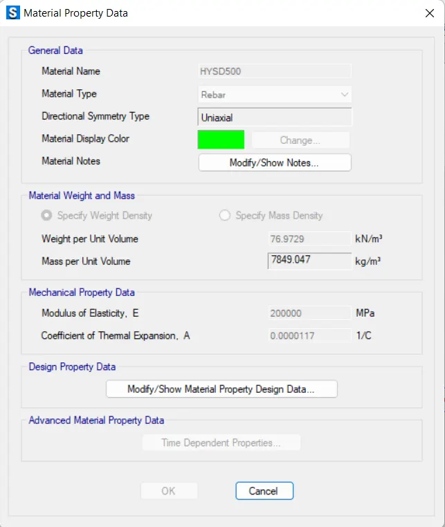
- Define the materials of concrete M25 Grade and longitudinal reinforcement as 500 Grade.
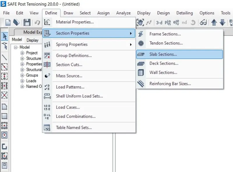
- Now select Section Properties under Define Tab.
- Select Slab Sections.
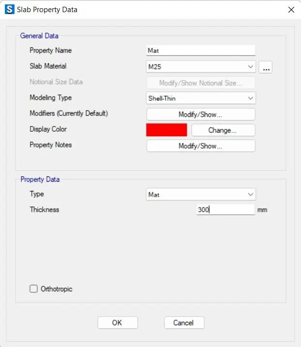
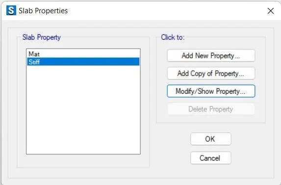
- Select Add new properties in Slab Properties.
- Define properties for footing.
- Define properties for Mat.
- Define Footing for Stiff.
- Define Load Patterrns.
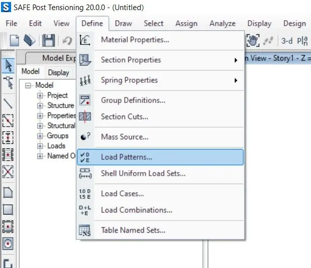
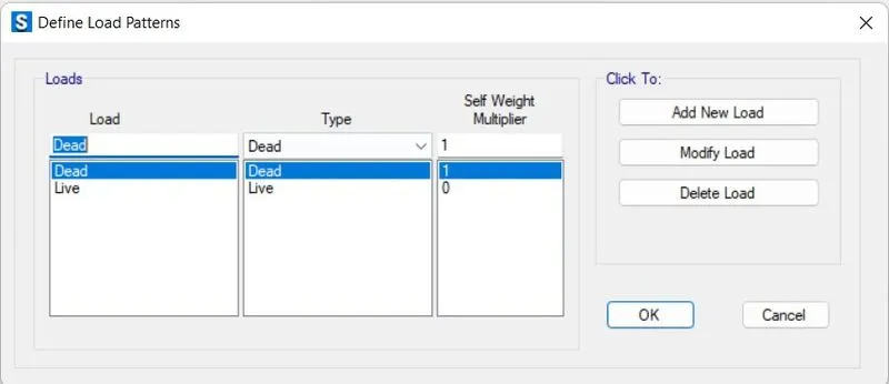
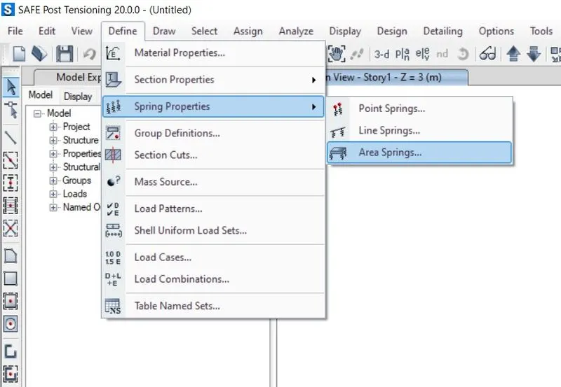
- Define Soil Subgrade Modulas / Area spring Property Data.
- Assign Point Load.
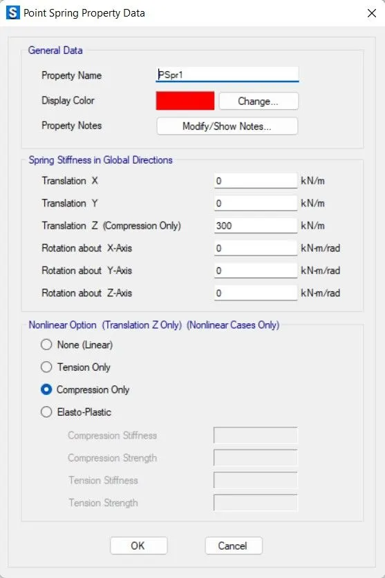
- Assign Point Loads.
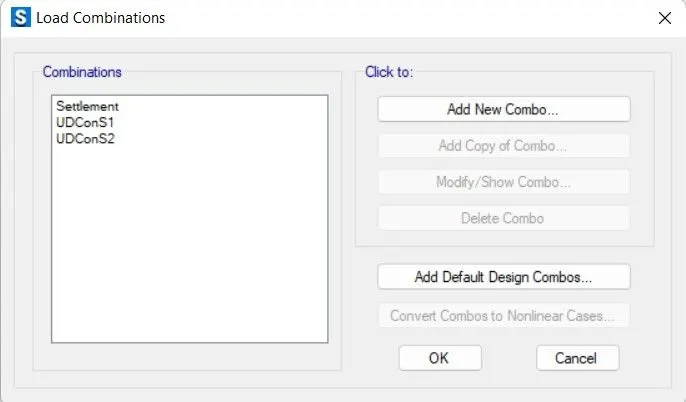
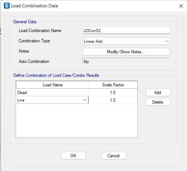
- Check Design Preferences.
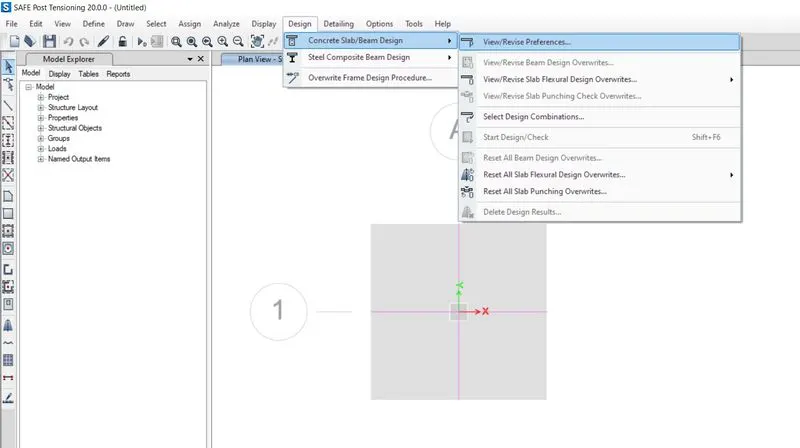
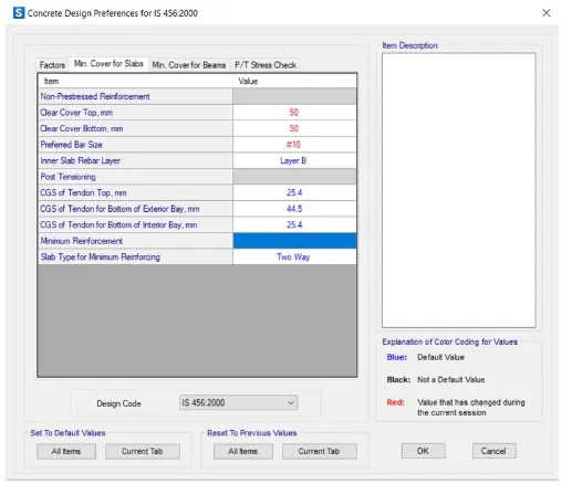
- Analyse the model using analyse option then click on check model the modelled structure is verified without errors and warnings.

- The model is alalyzed Successfully.
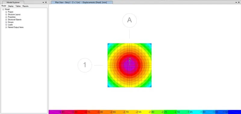
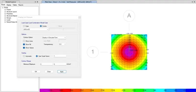
Safe Bearing Capacity :-
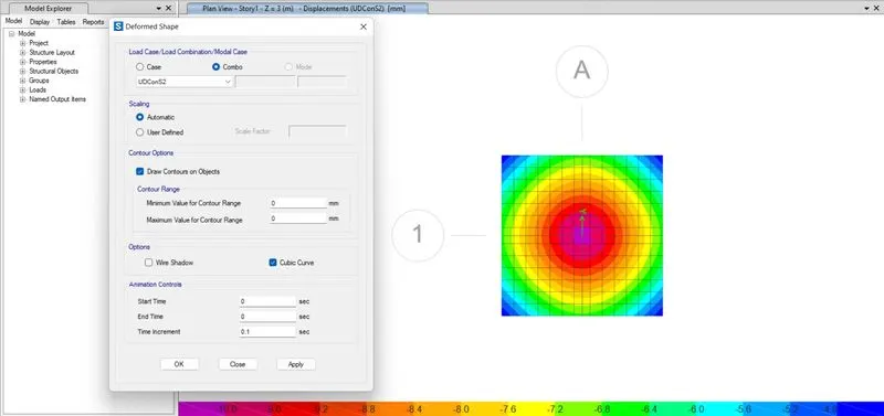
Deformed Shapes :-
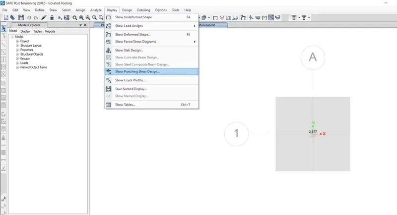
Two way Shear Check :-
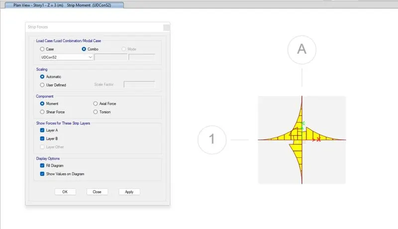
Bending Moment :-
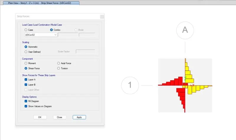
Shear Force :-
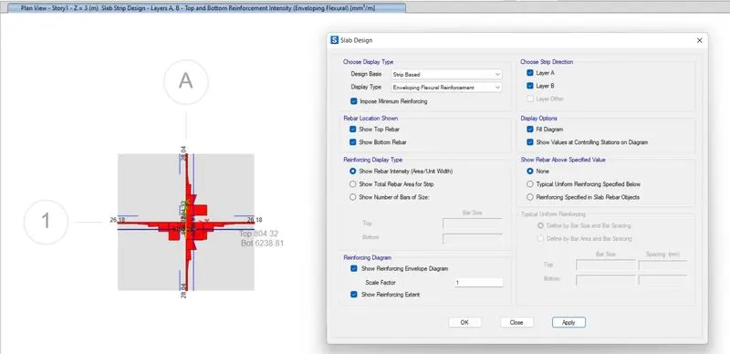
Flexural Reinfoecement Design foe Footing Slab :-
Result :-
- Created a model of the isolated footing provided in week 11 challenge on SAFE and analyzed and designed it to verify the size, depth and steel provided as per calculations.
2. A column of size 600x600 carrying an unfactored gravity load (DL+LL) of 1175 KN is to be supported on pile cap, which ultimately transfers load to the piles underneath. Piles of 16 metres length and 500 mm diameter are to be used. Each pile has a load carrying capacity of 200 KN. Model, analyse and design the pile cap on SAFE to evaluate the following:
- Pile group to be used
- Depth of pile cap
- Longitudinal steel on top and bottom face in both directions
Note: Participants must refer to IS 2911 (part 2) and SP 34 for 2nd challenge.
Introduction :-
- Pile foundation, a kind of deep foundation, is actually a slender column or long cylinder made of materials such as concrete or steel which are used to support the structure and transfer the load at desired depth either by end bearing or skin friction.
- Pile foundations are usually used for large structures and in situations where the soil at shallow depth is not suitable to resist excessive settlement, resist uplift, etc.
Aim :-
-
To model, analyse and design the pile cap on SAFE to evaluate Pile group to be used ,Depth of pile cap, Longitudinal steel on top and bottom face in both directions.
Procedure :-
Given.
Column size = 600 X 600mm
Factored load = 1175 KN
Pile length = 16 m
Pile Diameter = 500 mm
Load carrying capacity = 200 KN
Calculations.
Number of Piles = 1175 / 200
= 6 Piles
Spring Constant = E*A / L
= 25000* 196375 / 16000
= 306835 N/mm.
Edge spacing is taken as 200 or 300 mm.
- Open SAFE 2020.
- Select New Model.
- Now, New dialogue box will open named model Initialization.
- Select Units and Codes as per your project.
- we have selected Indian codes and units as Metric SI.
- Now select the uniform grid spacing.
- Select Single Footing.
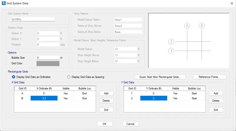
- Coordinates was defined next.
- Grid in X and Y direction ar e taken as 3.2 and 2 m respectively.
- Select Material properties under define tab.
- New dialogue box will appear named Define Materials.
- Select Add new Material from the window.
- Define the materials of concrete M25 Grade and longitudinal reinforcement as 500 Grade.
- Now select Section Properties under Define Tab.
- Select Slab Sections.
- Select Add new properties in Slab Properties.
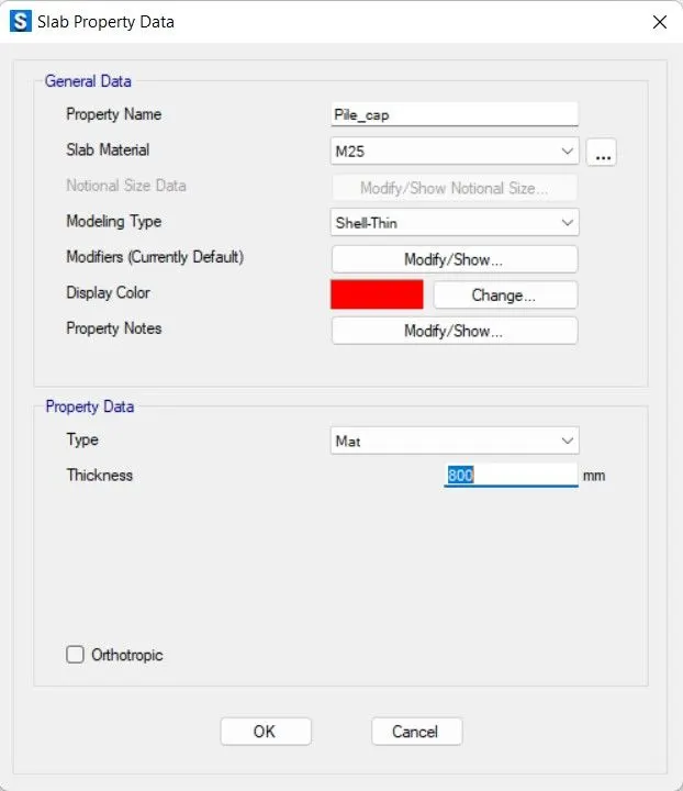
- Define properties named as Pile Cap.
- Define Column for Stiff.
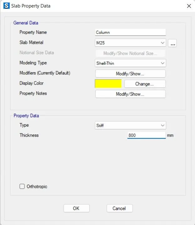
- Define Pile for Mat.
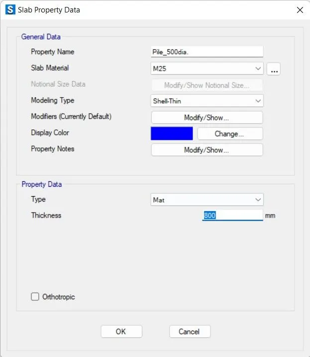
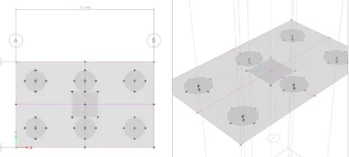
- Draw the slab from Quick draw Slabs.
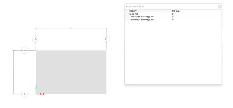
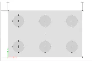
- Add piles at the Points.
- Modify edge distance to 0.2m.
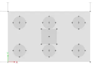
- Create a column of 600X600mm.
- Draw the cloumn in the center.
- Spring were added.
- Define spring Property data.
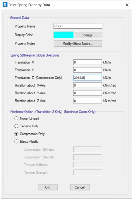
- Select Pile -> Assign -> Support Data -> Point Springs.
- Spring Constant is taken from above calculation.
- Dead load and Live Loads are 587.5 KN.
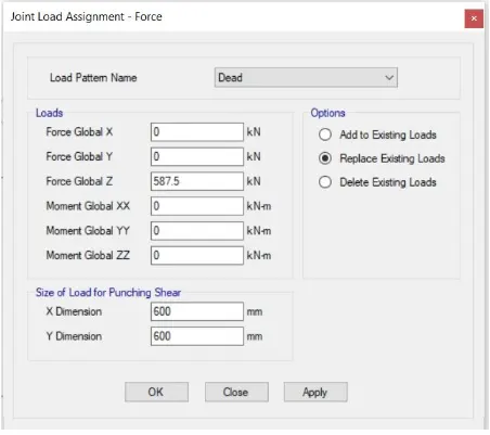
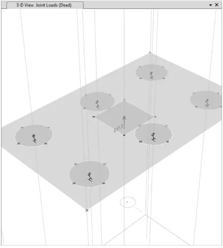
- Load Case combination was defined Next.
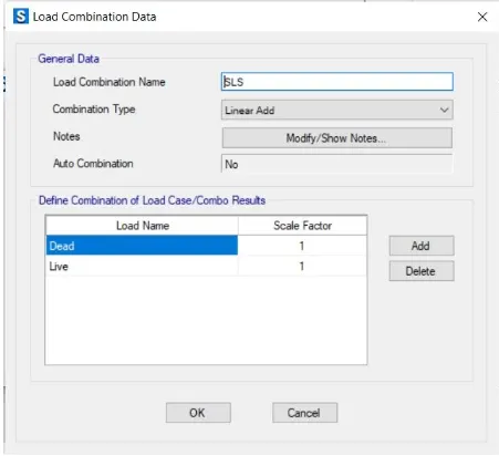
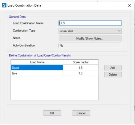
- Analyse the model using analyse option then click on check model the modelled structure is verified without errors and warnings.
- The model is alalyzed Successfully.
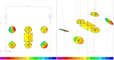
- Maximum displacements are found safe.
- All the punching shear values ar less than 1.
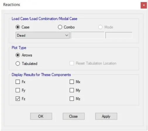
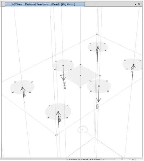
- JOint reaction diagram, as all the reaction force are according to limit.
- Reinforcement details are added next.
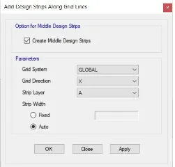
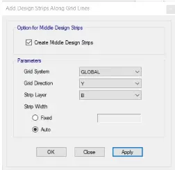
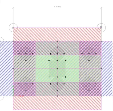
- Run analysis again.
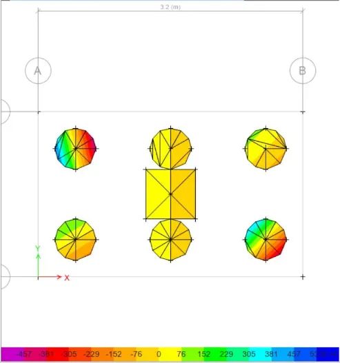
Reinforcement Slab Design :-
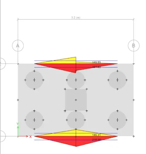
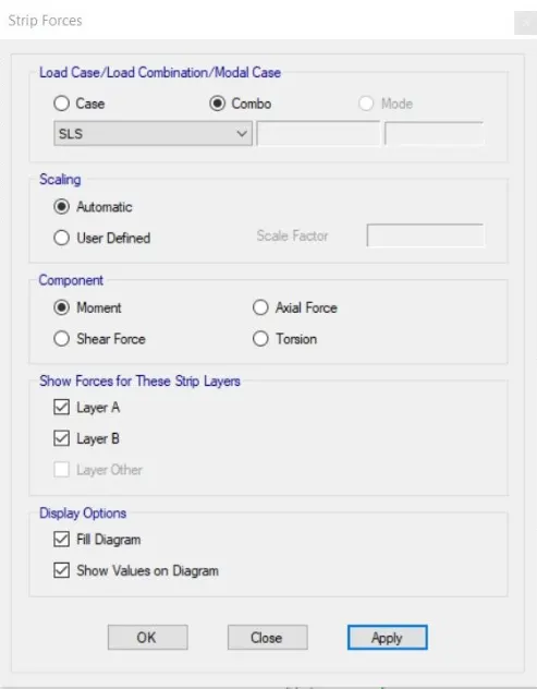
Bending Moment :-
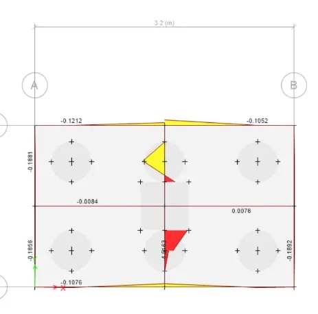
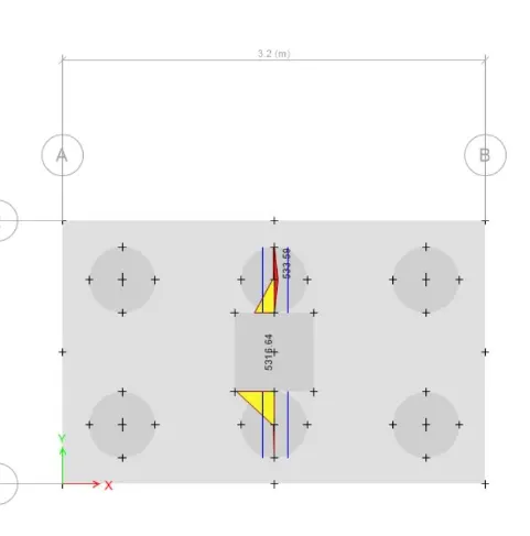
Shear Force :-
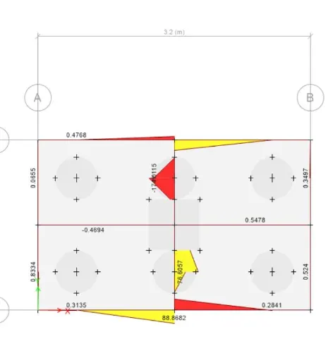
Result :-
- Created a model, analysed and designed the pile cap on SAFE to evaluate Pile group to be used, Depth of pile cap, Longitudinal steel on top and bottom face in both directions.