Foundation Design using SAFE
1)ANS
AIM:
The Isolated footing provided in week 11 challenge on Safe.
Analyze and design it to verify the size, depth and Steel provided as per calculations.
PRODUCE:
STEP-1:
- Frist open the CSI SAFE Software 20
- Next select the New model
- Next model intialization
- Select the Initialzation option
- Select the click ok

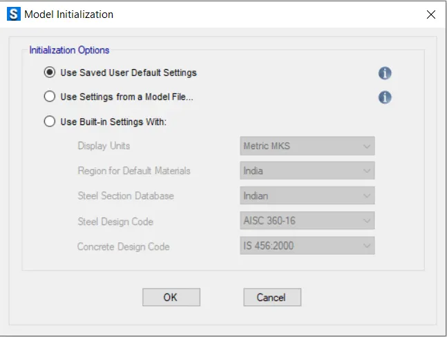
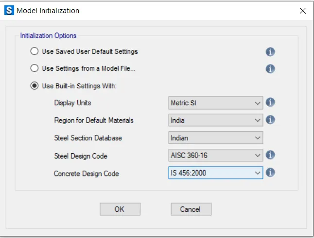
STEP - 2:
- Next select the New model Quick Templates
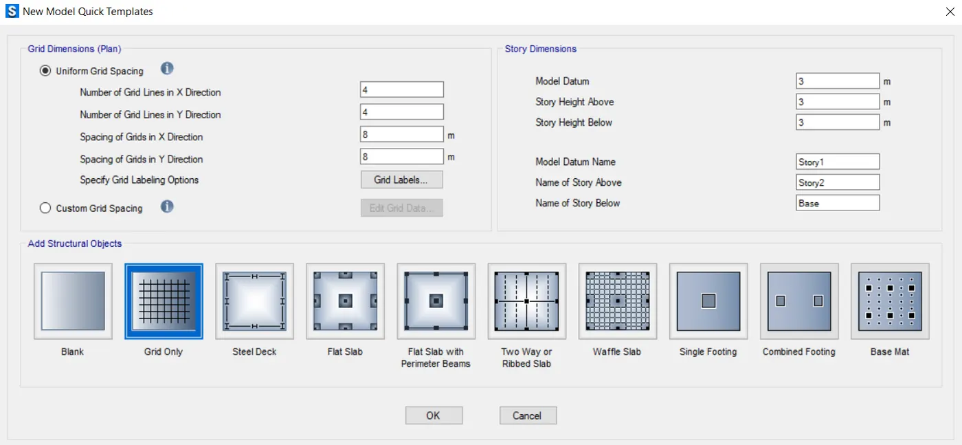
- Next select the Single Footing
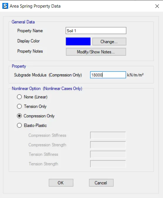
- Subgrade modulas = FOS * SBC / Max Settlement
= (3*150)/0.05
= 9000KN/M^3.
The Compression axial load for load conbination (1.5 Deal Load + 1.5 Live Load) is 2000KN.
Unfactored load = 2000/1.5
1333.3KN
Deal Load Breakup = 1333.3/2
666.5 KN
Live Load Breakup = 1333.3/2
= 666.5KN
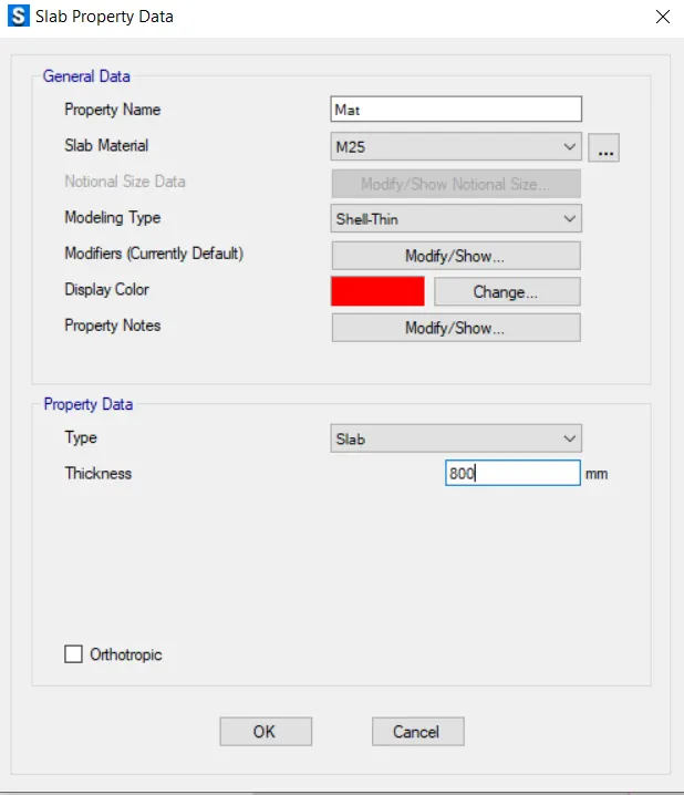
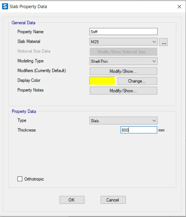
So Footing Thickness is 8000MM.
- Next Structural Geometry and properties for Single footing
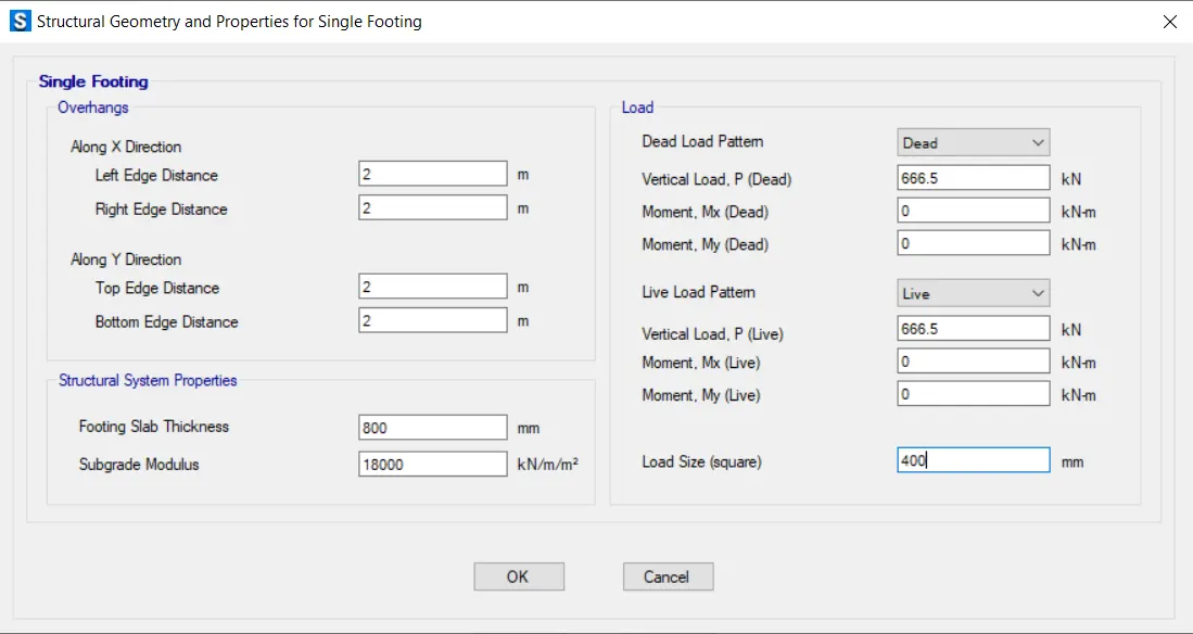
- So Single footing added
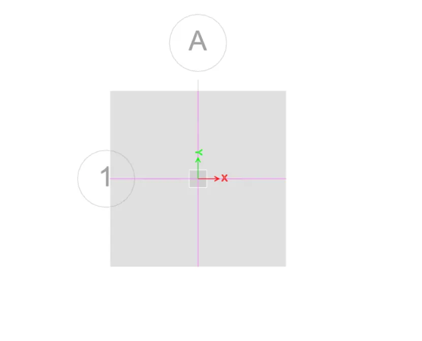
STEP - 3 :
- Next the Select the Material Properties
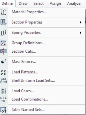
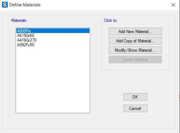
- So Define Materials and Click to added the New material
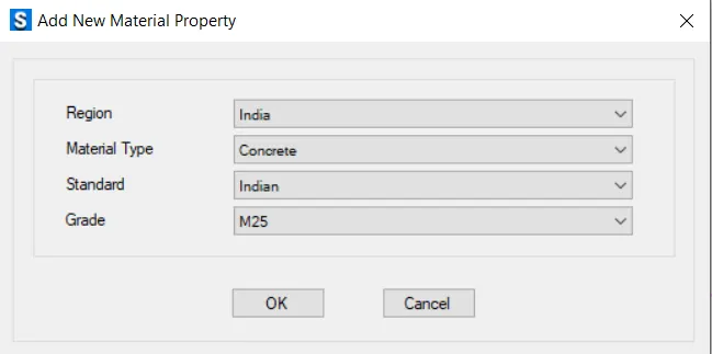
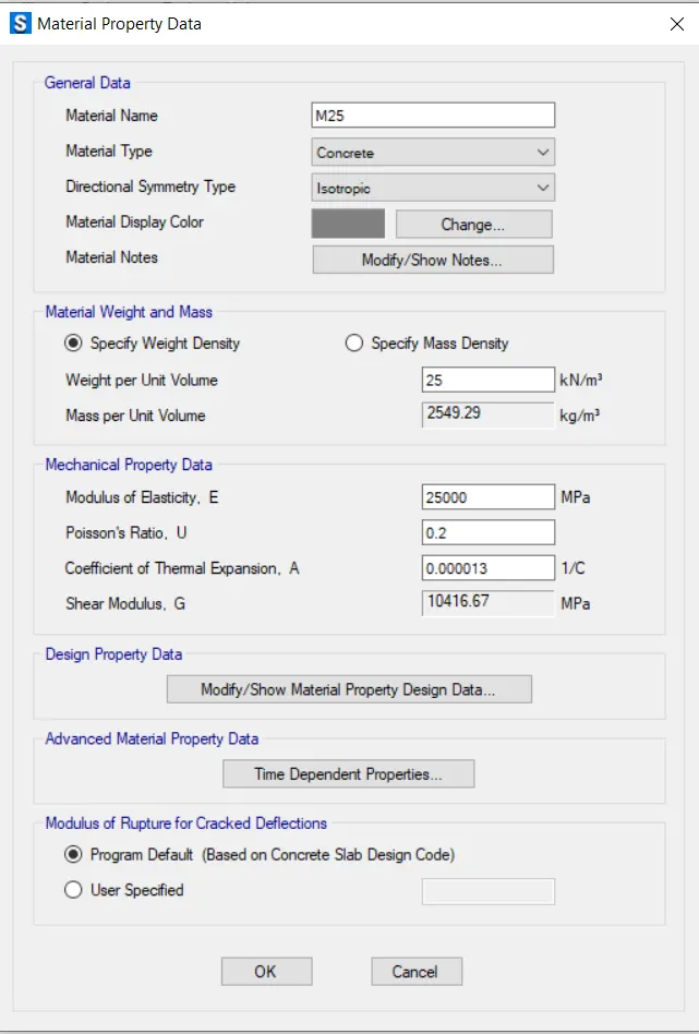
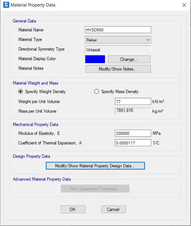
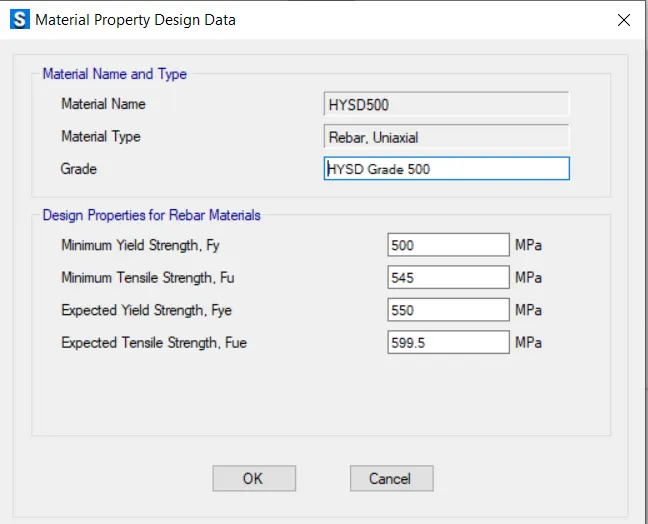
- Add New Material property Fck 500, M25

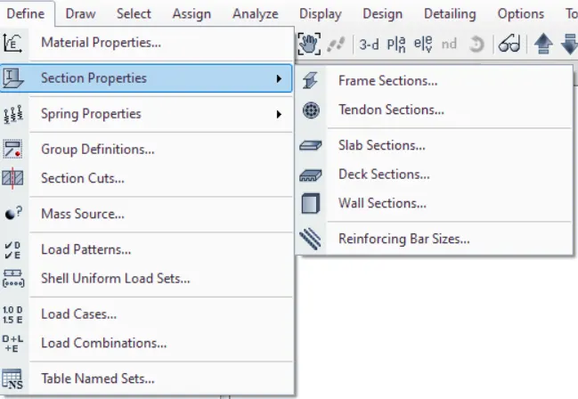
- Next select the Section propeties
- Select the Slab sections
- Next the Add new property
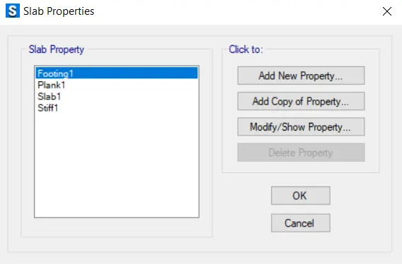
- Define the MAT and Stiff
STEP - 4 :
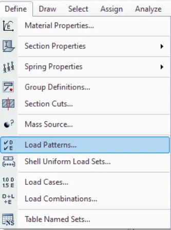
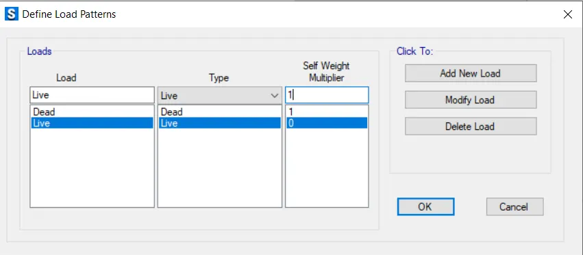
- Next Define Load patterns
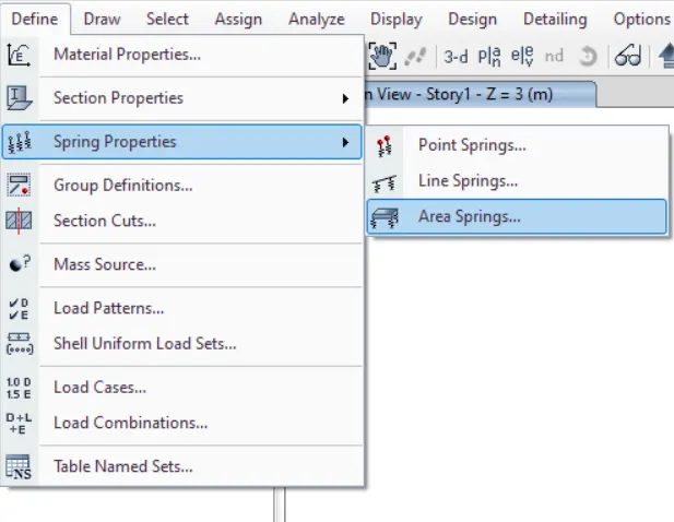
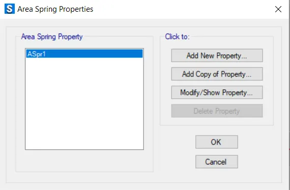
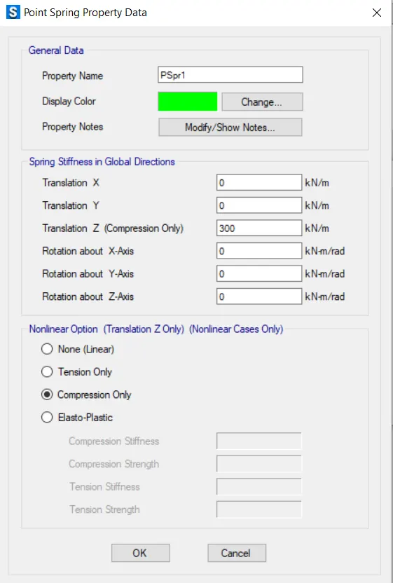
- Next Define the Soil subgreade modula/ Area spring property Data.
- Assiged Point Load
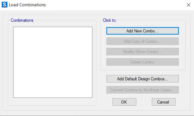
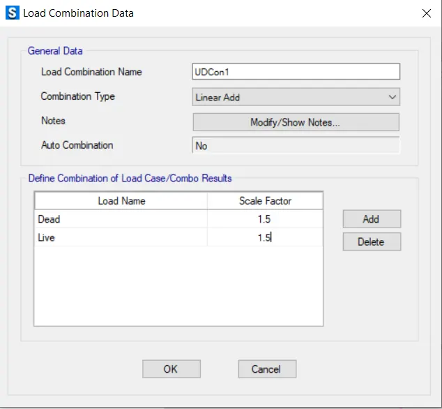
- Assiged Load Combinations
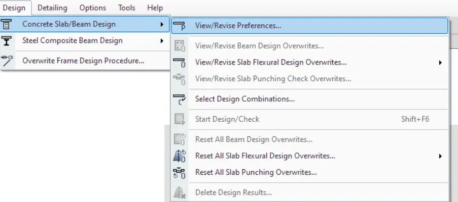
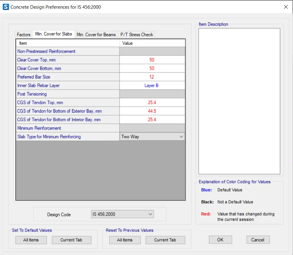
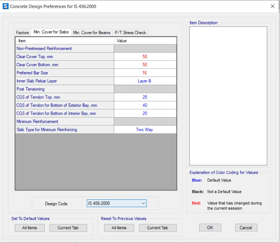
- Check Design Preferences
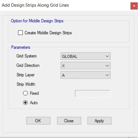
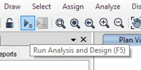
- Analyse the model using analyse option then click on check model the modelled structure is verified without errors and warnings.
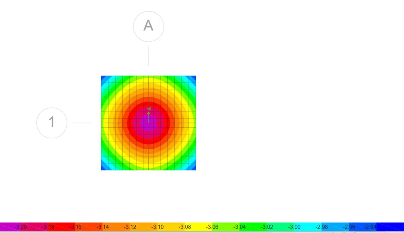
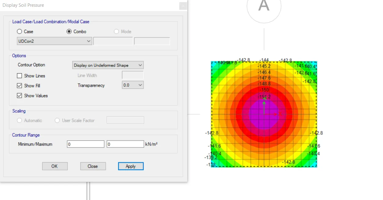
Safe Bearing Capacity:
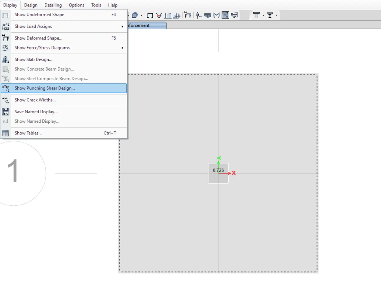
Two way shear check:
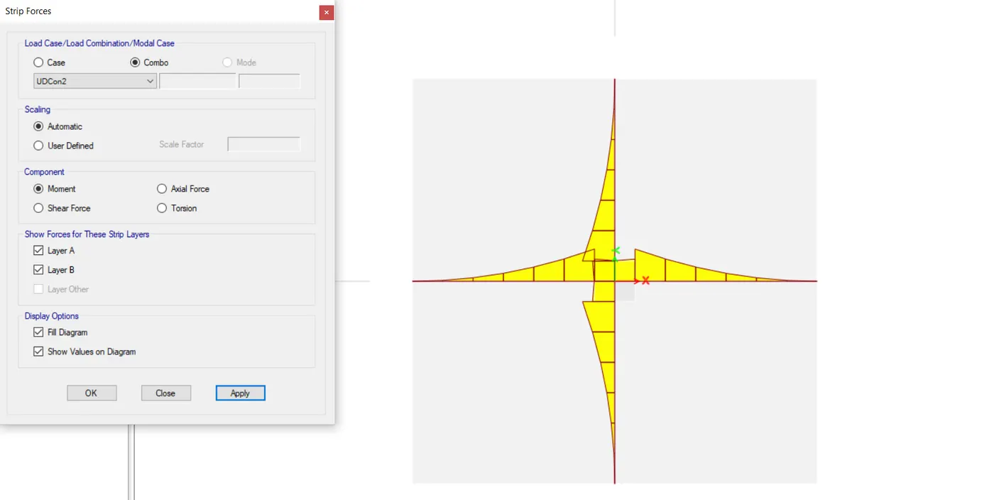
Beading Moment:
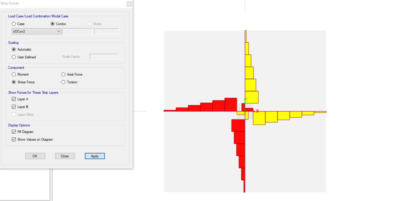
Shear Force:
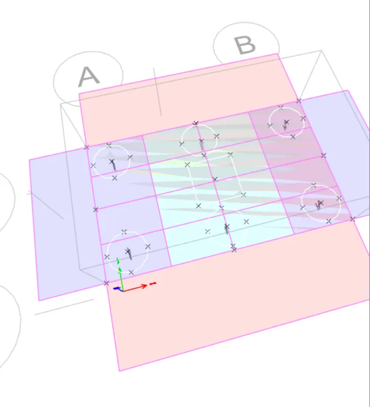
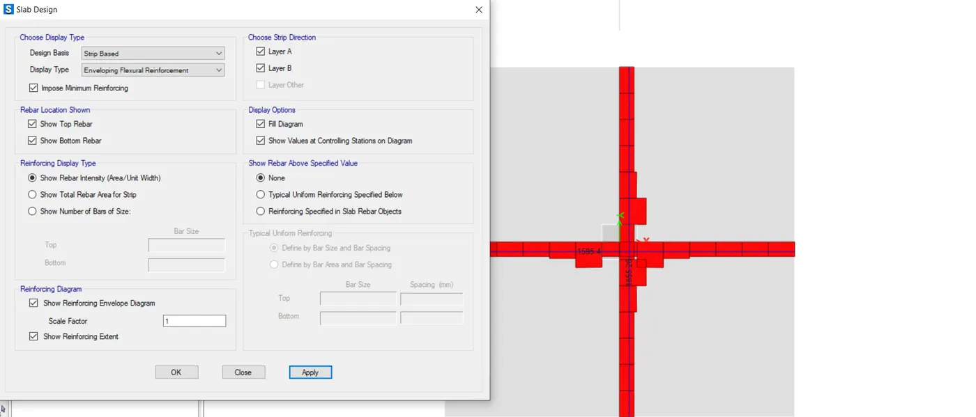
Flexural Reinforecement Design For Footing Slab:
2)ANS
AIM:
The Analyse and Design the Pile cap on SAFE to evaluate pile group to be used Depth of pille cap, Longitudinal steel on top and bottom face in both directions.
PROCEDURE:
Given Data
Column size = 600 X 600mm
Factored load = 1175KN
Pile length = 16m
Load carrying capacity = 200KN
Calculations.
Number of piles = 1175/200
= 6piles
Spring constant = E*A/L
= 25000*196375/16000
= 306835 N/mm
Edge spacing is taken as 200 or 300 mm
STEP-1:
- Frist open the CSI SAFE Software 20
- Next select the New model
- Next model intialization
- Select the Initialzation option
- Select the click ok
STEP - 2:
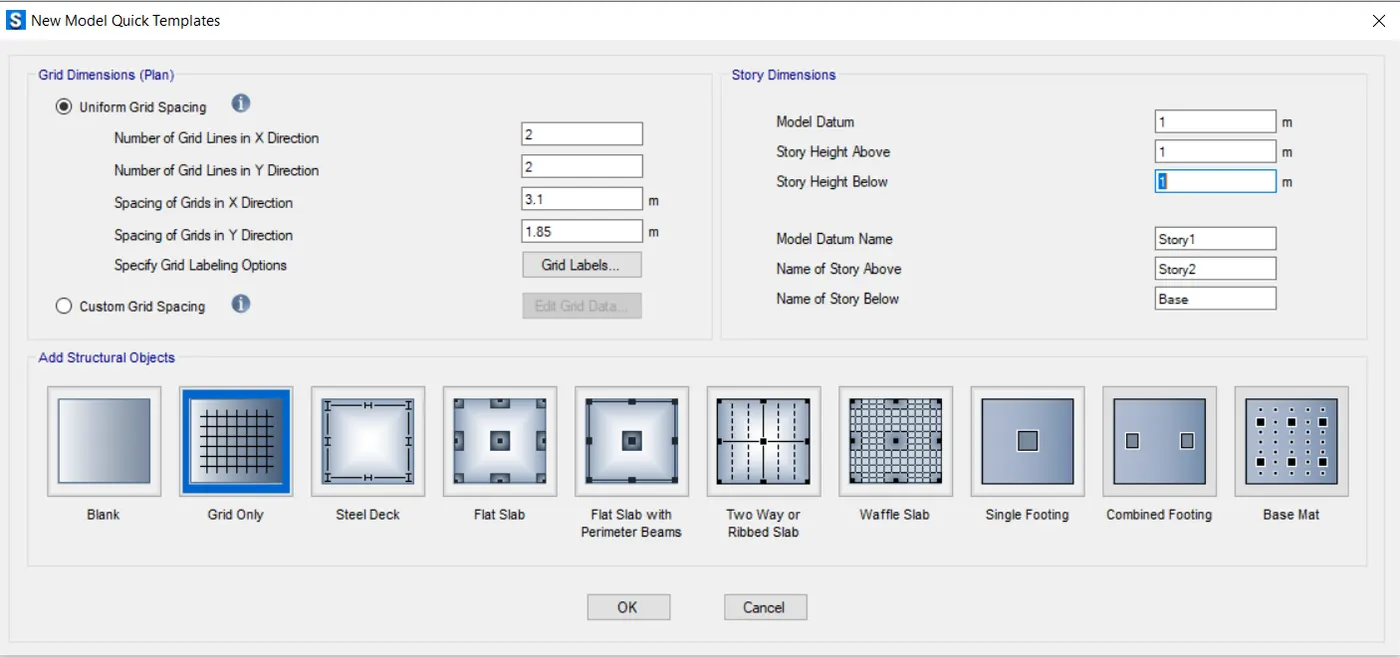
- Now select the uniform grid spacing.
- Select single footing.
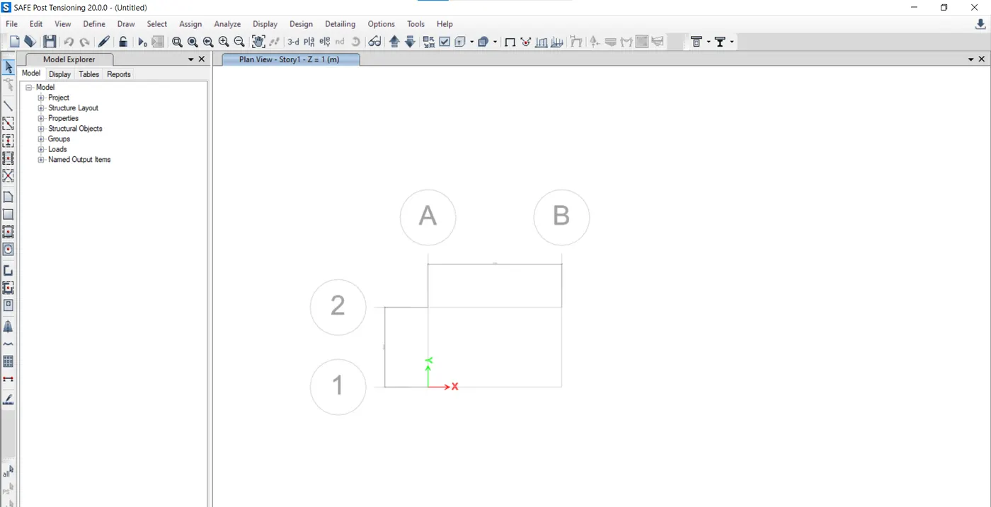
- Corrdinates was define next
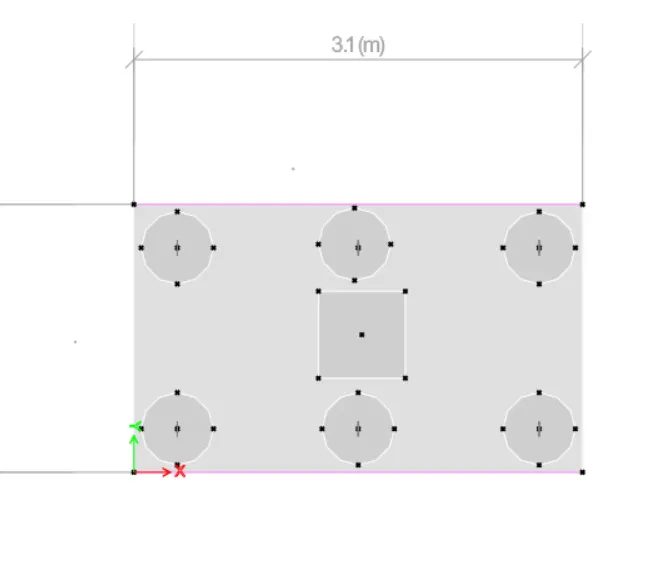
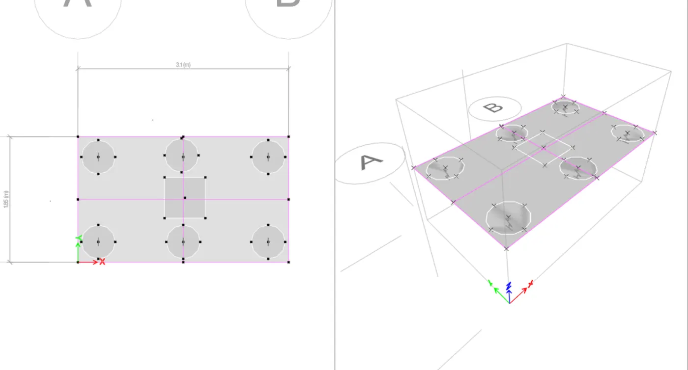
- Grid in X and Y direction or taken as 3.2 and 2m respetively.
STEP - 3:
- Now we have to assign the
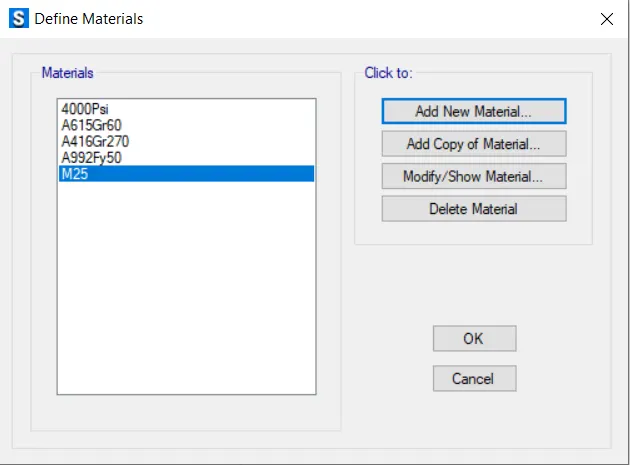
- Material properties Define -Material propeties
- Click on add new materials
- Once you click add new material the following parameters
- Material type - concrete
- M 25
- Simialarly add the Rebar properties
- HYSD Grade 500
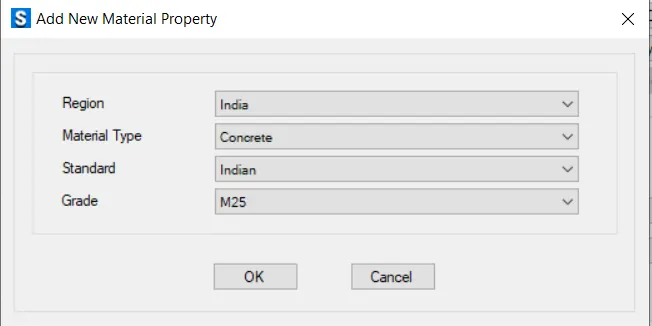
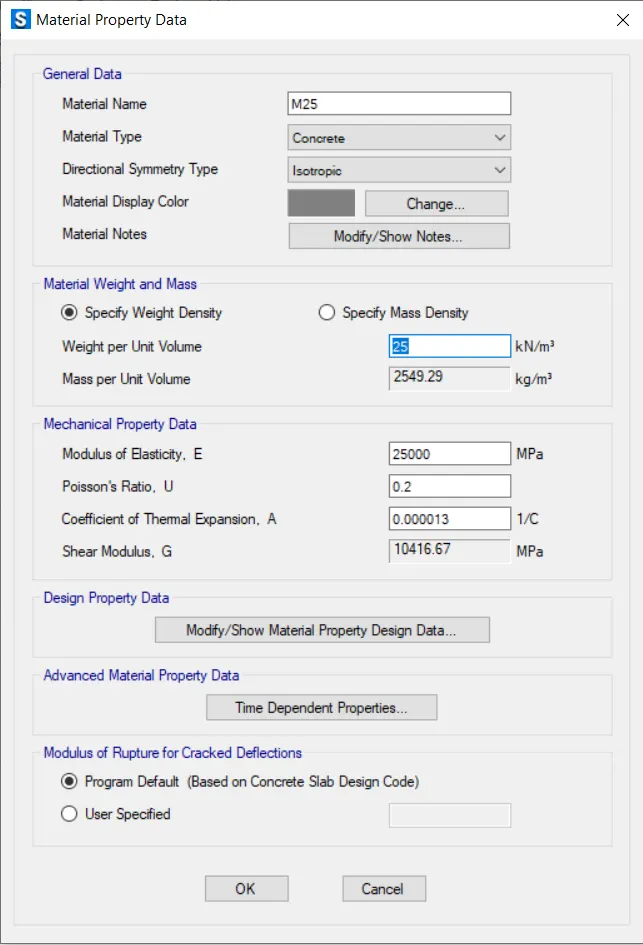
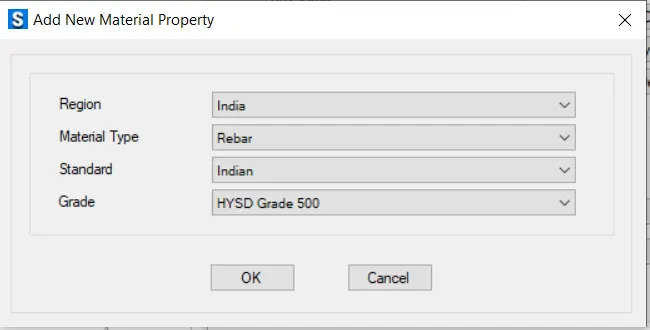
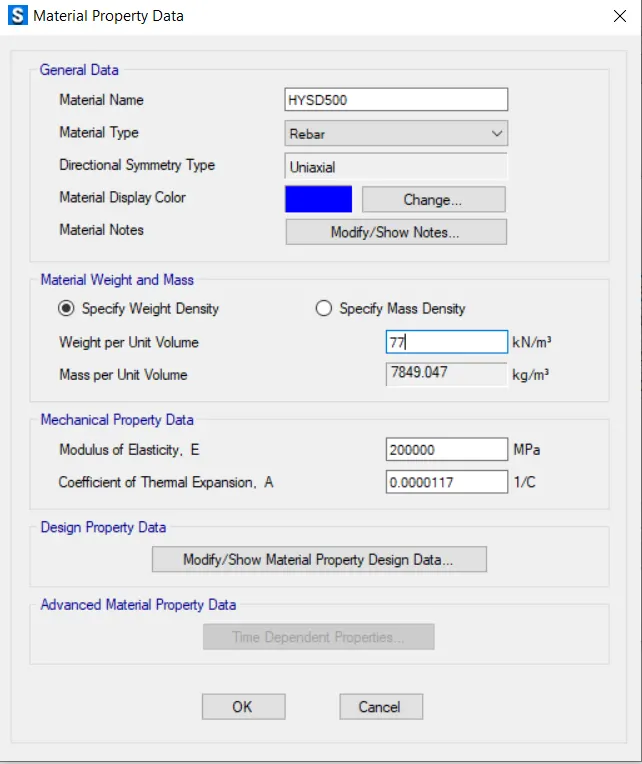
STEP - 4:
- Now we have to define slab properties
- In pile cap we have to define 3 Slab properties
- Footing
- For column
- For pile cap
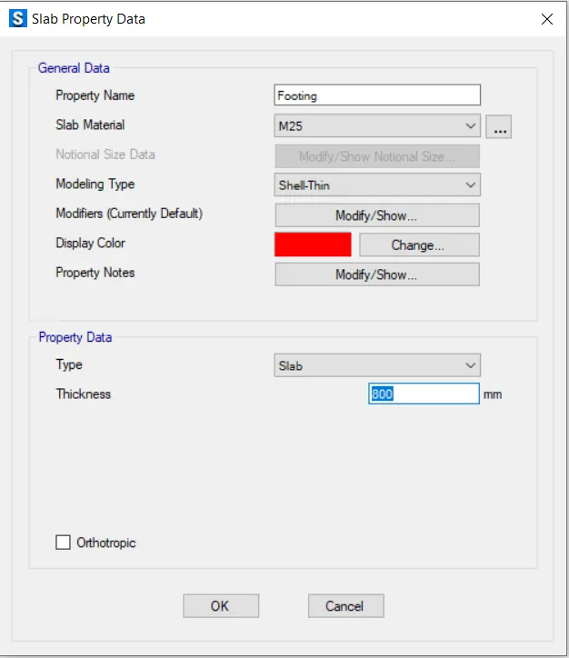
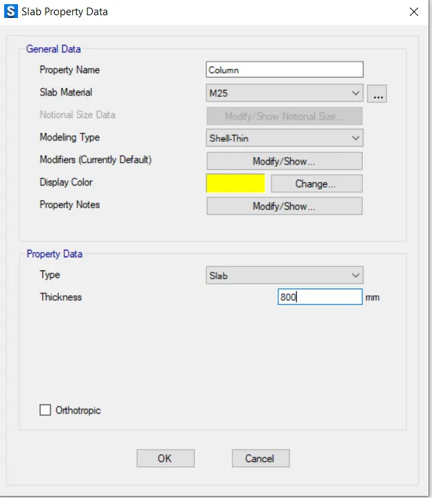
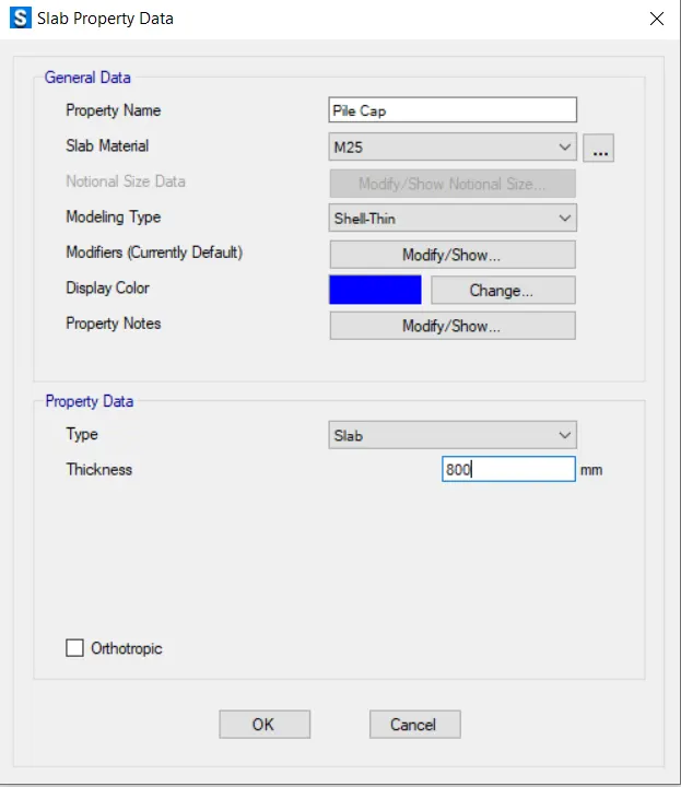
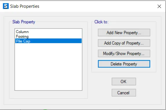
STEP - 5:
- Once slab properties are defined
- Now we have to start the modeling
- Select Quick draw slab option
- Draw the slab select footing as property
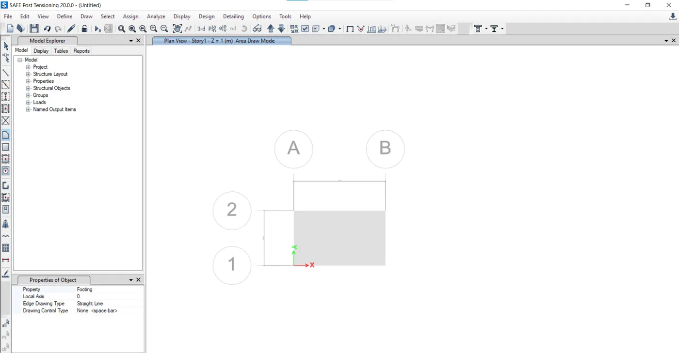
STEP - 6:
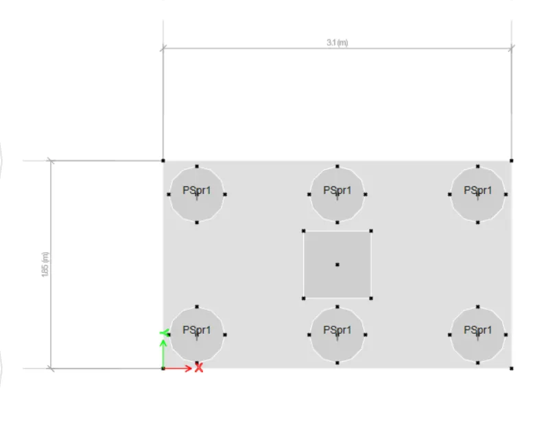
- Now we have to Mark the position of pile cap
- For the we have to add the points
- Draw-Draw reference points
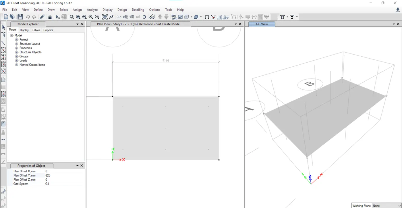
STEP - 7:
- Add Piles at the point
- Modify the edge distance to 0.3m
- Now we have to add column slab
- Click on Quick draw area / point
- Select the property
- and Draw the column
- Similarly draw the pile caps
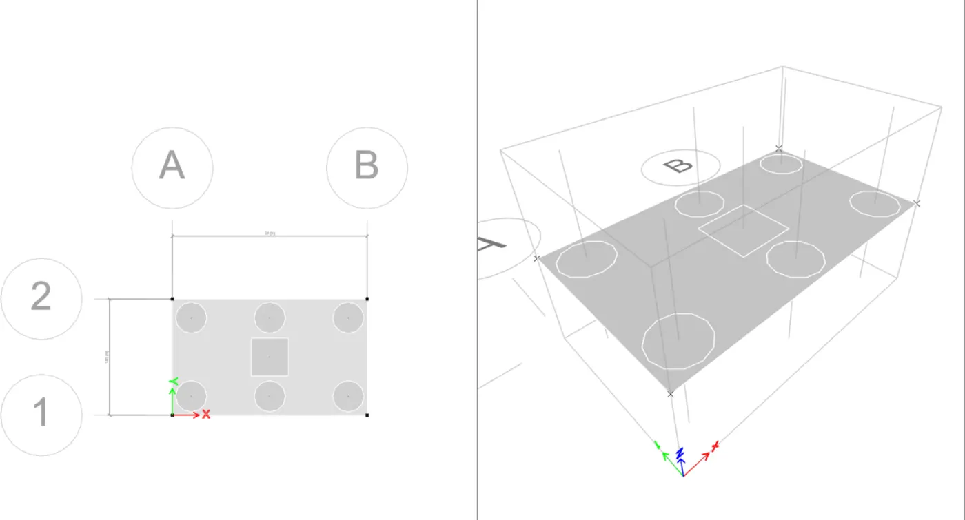
STEP - 8:
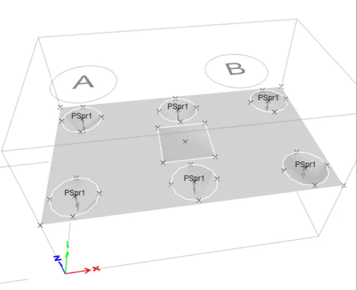
- New we have to add springs to the pile because it behaves like a spring
- Cilck on Assign - Support data-point spring
- Spring constant from above calculation is take as
- Add spring constant - 306795 kn/m
- Select -compression only
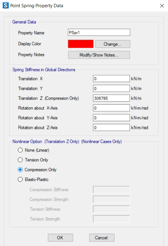
STEP - 9:
- Click on okay
- Spring constant has been assigned
STEP - 10:
- Now we have to add the loads
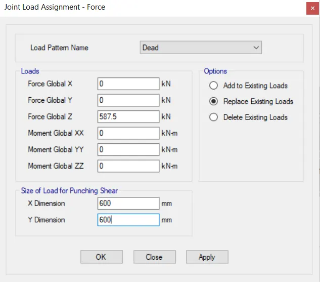
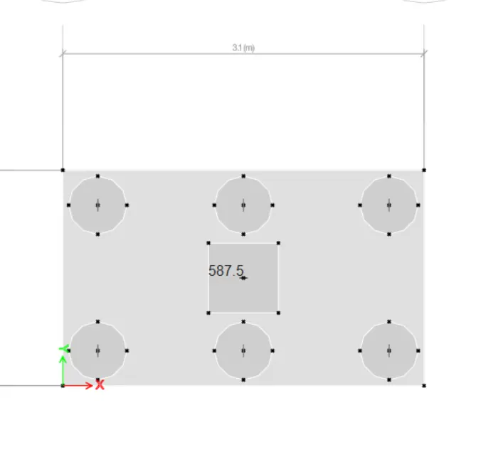
- Go to Assign joint loads force
- Assign 587.5KN dead load and 587.5KN Live load
- Load case combination was defined next
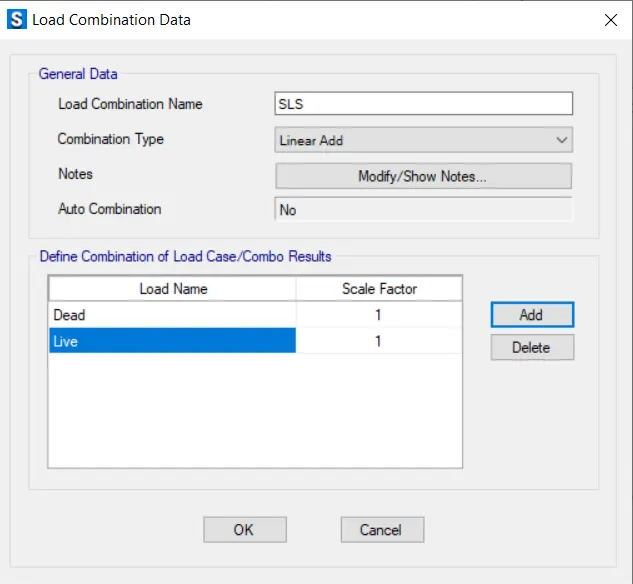
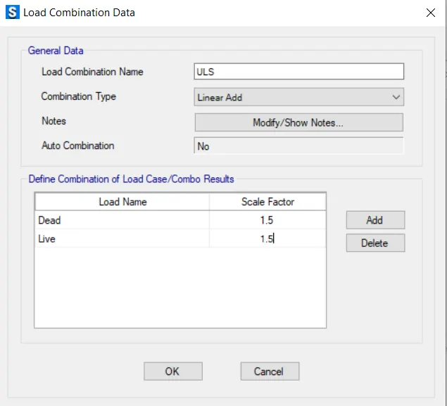
- Analysis the model using analysis option then click on check model the modelled structure is verified without errors and warnings.

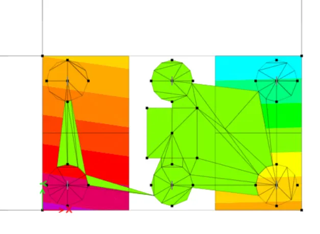
- Maximum displacement are safe.
- All the ounching shear values or less than 1.
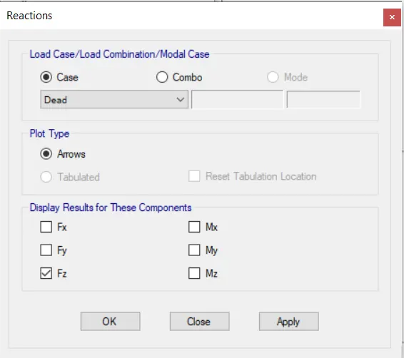
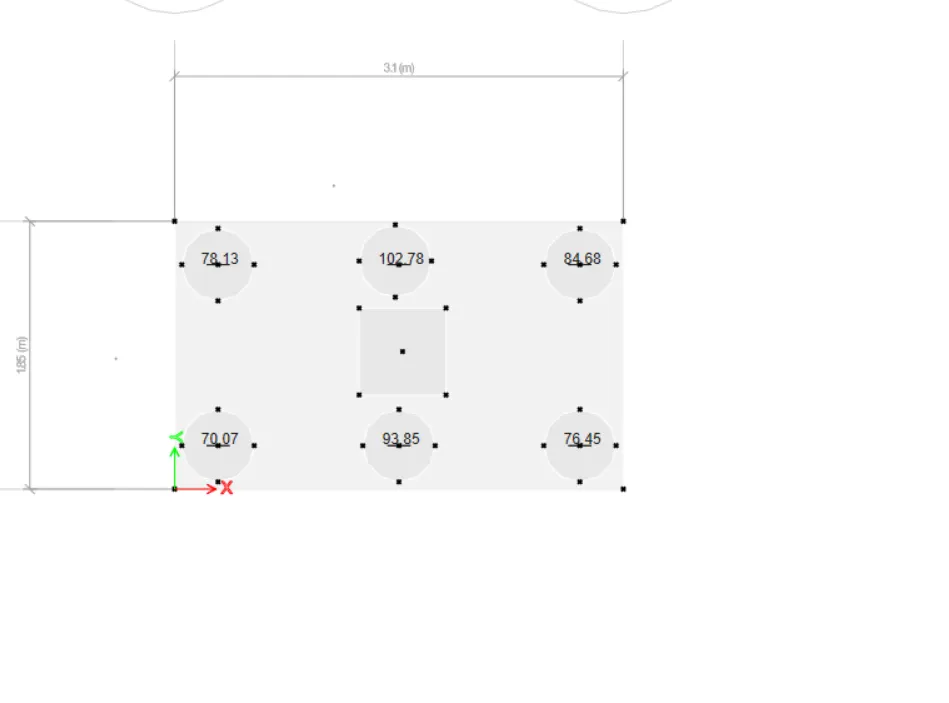
- Joint reaction diagram, as all the reaction force are accoring to limit.
- Reinforecement details are added next.