Foundation Design using SAFE
ISOLATED FOOTING
The details of the Isolated Footing be,
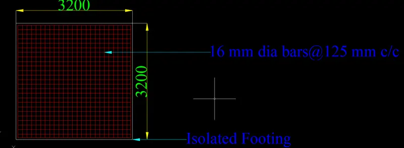
Isolated Footing Size=3.2 m X 3.2 m
Column Size=400 mm X 400mm
Factored Load=2000 KN
Unfactored Load=2000/1.5=1333.33 KN
fck=25 N/sq mm
fy=415 N/sq mm
Safe Soil Bearing Capacity=150 KN/sq m
=>Dead Load=1333.33/2=666.66 KN
=>Live Load=1333.33/2=666.66 KN
Subgrade Modulus of Soil=Safe Bearing Capacity X Ultimate Factor/Settlement=150 X 3/0.05=9000 KN/ cu m
Initially,to design an Isolated Footing using SAFE software,after opening the software,we go to New Model option.
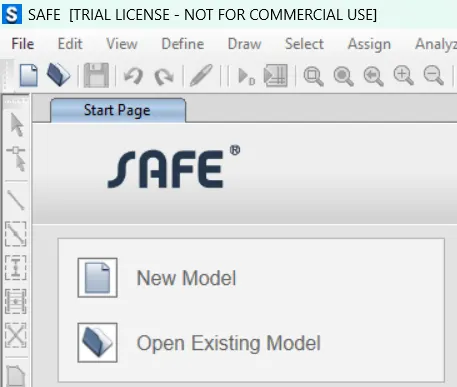
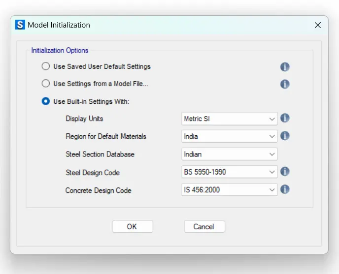
Where then we initialize the new model with the Model Initialization Tab as below.
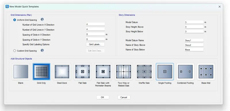
We then select the Single Footing template in New Model Quick Templates Tab.
We then give the respective loadings and the dimensions of the footing as well as the column too.
We even enter the subgrade modulus of the soil.
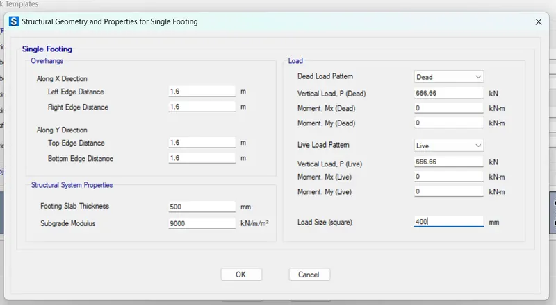
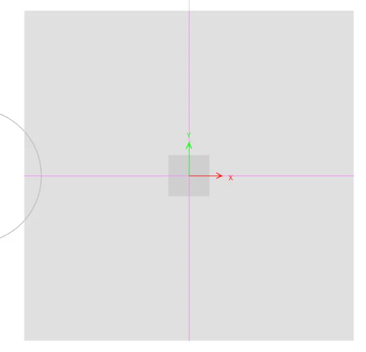
Then automatically an Isolated Footing is formed.
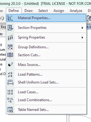
Then we define the new materials to be used for the footing.For that we go to Define Tab>Material Properties...
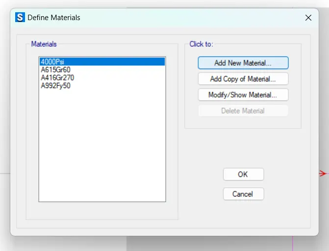
We then click on the Add New Material... similar to that of the ETABS software.
Where we create the materials i.e.,M25 and Fe415 as shown.
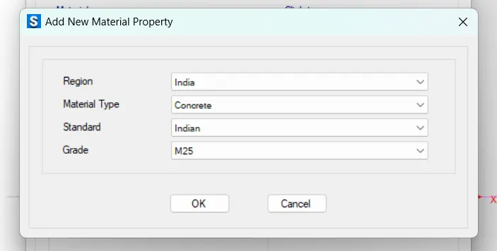
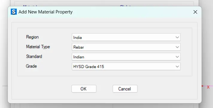
After the definition of the materials,we have to verify the materials assigned to the Footing where by default few will be added to those but we have change as per our requirement.
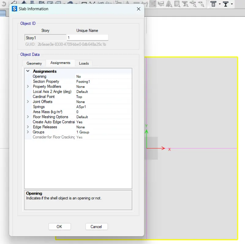
From the above,we can find that Footing 1 is assigned to the Isolated Footing where we change it as per our requirement.
To do that,we go to Define Tab>Section Properties>Slab Sections...
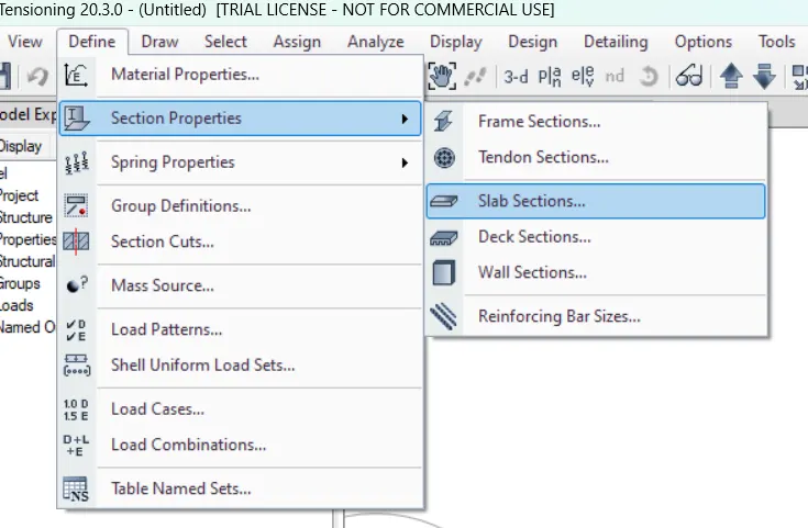
So instead of the creation of the new property we do change the already assigned property.
We then select the Footing 1 option where we then change as shown.
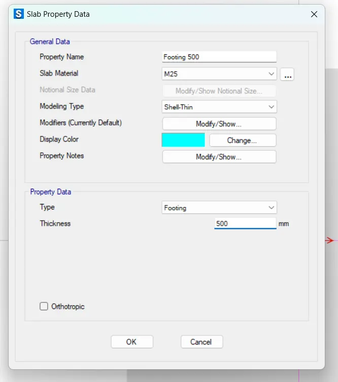
In the same manner we do even verify for the area under the column.
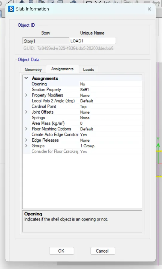
And we do modify the already assigned slab property.
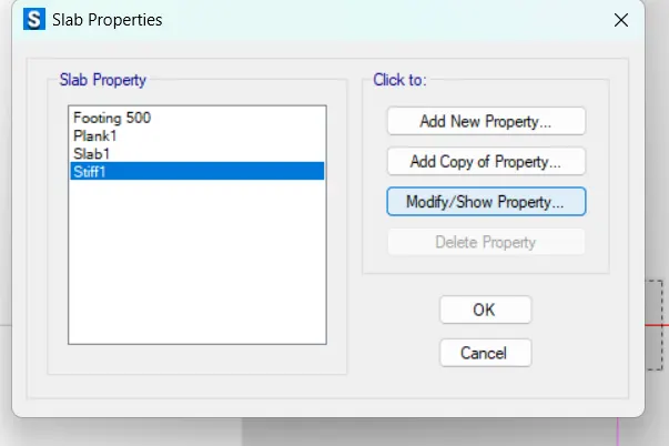
The we select the option of Stiff 1 and go to Modify/Show Property...
Then we modify as per the requirement.
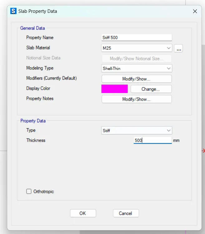
And again verify wheather it's updated or not.
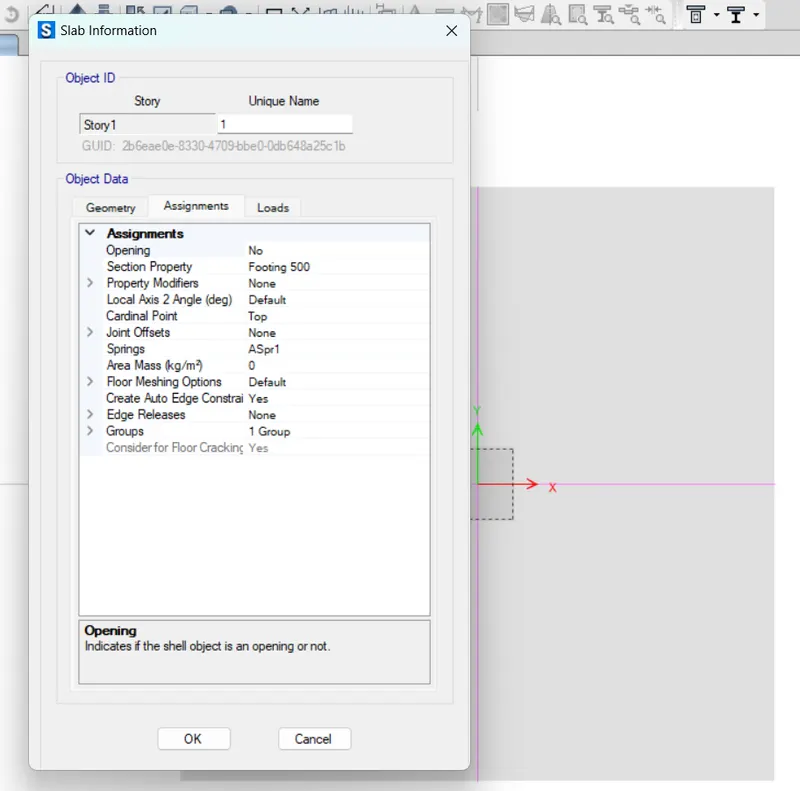
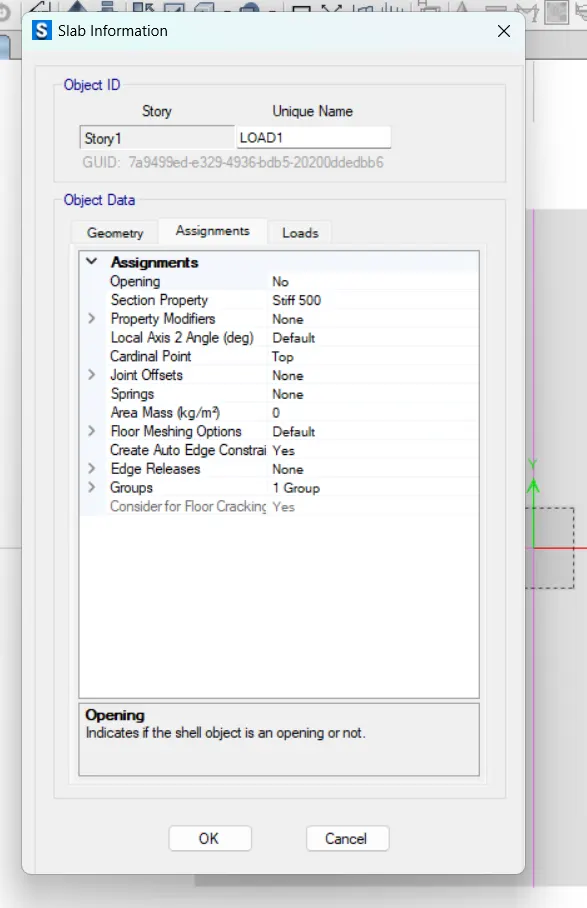
Anyway,the loads are already being assigned where we check wheather the loads are assigned or not.
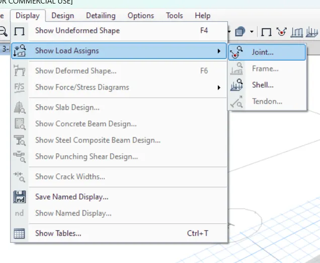
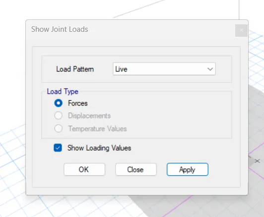
We then go to Display Tab>Show Load Assigns>Joint...
Then we select the Load Pattern and click on Apply.
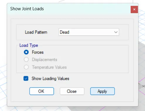
Where we check both the type of loads i.e.,Dead and Live Load.
And the selected loads will be dispalyed on the screen at the point.
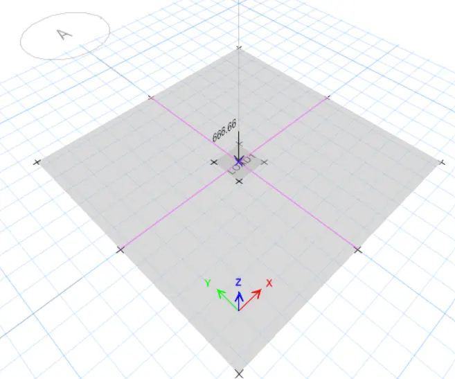
After the checking of the application of the loads,we run the analysis.
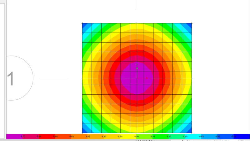
Settlement
Where the settlement of the foundation at different points is shown.
Here,we can find the settlement is at maximum of around 9 mm but we had limited it to 50 mm,so it's safe as per the settlement.
Punching Shear
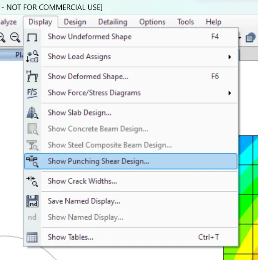
We then check for the Punching Shear,where we go to Display Tab>Show Punching Shear Design...
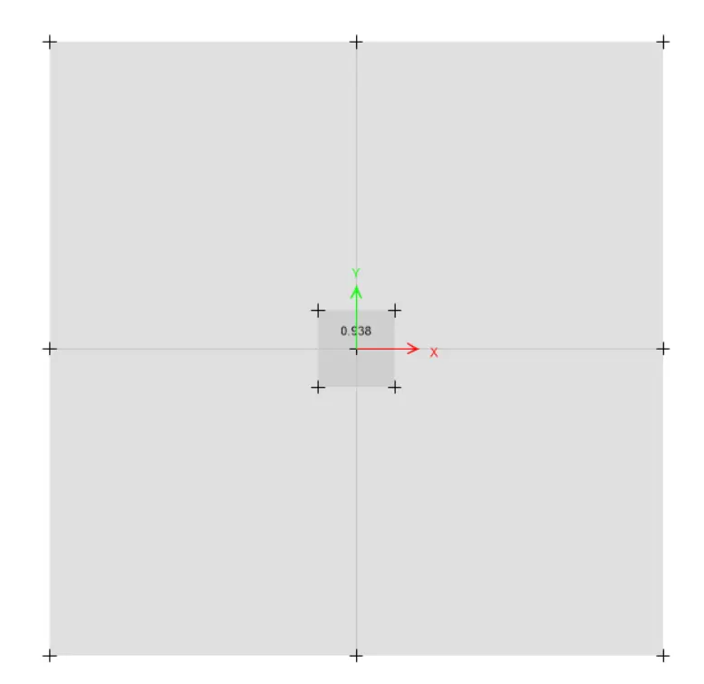
Where we can find it's value as 0.938<1,so it's safe as per the Punching Shear.
Reinforcement
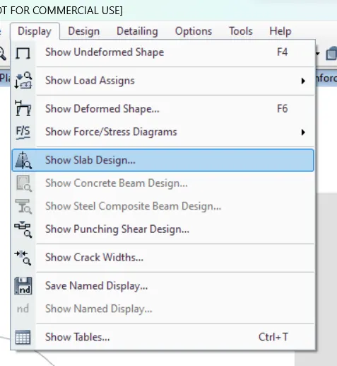
We have to check the reinforcement,where we go to Display Tab>Show Slab Design...
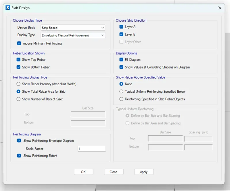
We then select the required details in the Slab Design Tab.
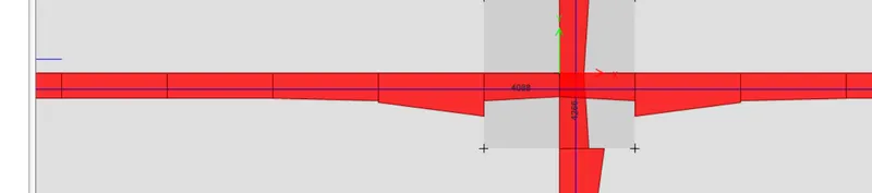
Where we get the reinforcement values in the both directions.
Where we find the provided reinforcement of 5425.825 sq mm which is greater than the values as per the SAFE software in both the directions.
We provide 16 mm dia bars@125 mm c/c.
PILE FOUNDATION
The details of the Pile Foundation be,
Column Size=600 mm X 600 mm
Unfactored Load=1175 KN
Pile Length=16 m
Pile Diameter=500 mm
Pile Capacity=200 KN
=>Dead Load=587.5 KN
=>Live Load=587.5 KN
Point Spring Modulus=A X E/L=(3.14 X 250 X 250 ) X 25000/16000=306640.625 N/mm=306640.625 KN/m
No. of Piles=Unfactored Load with the addition of Self Wt./Pile Capacity=1175 X 1.1/200=6.46=>7=>8 Piles
We use the even no. of piles for the symmetry purpose.
c/c Distance b/w Piles=3 X d=3 X 500=1500 mm
Edge Distance=d=500 mm
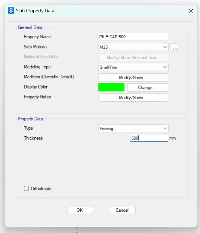
Pile Cap Depth=500 mm
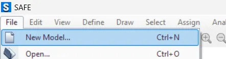
Initially,to design the Pile Foundation,after going to the SAFE software,we go to File Tab>New Model...
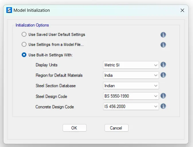
Where we initialize the model using the Model Initialization Tab with the relevant details.
Where we then select the Blank Template in the New Model Quick Templates Tab.
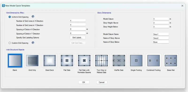
Then we go with the definition of the materials.
Where we go to Define Tab>Material Properties...
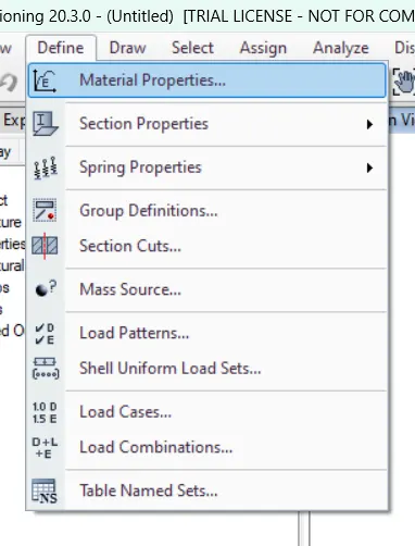
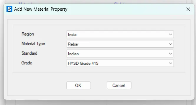
We then click on the Add New Material... in the Define Materials Tab.
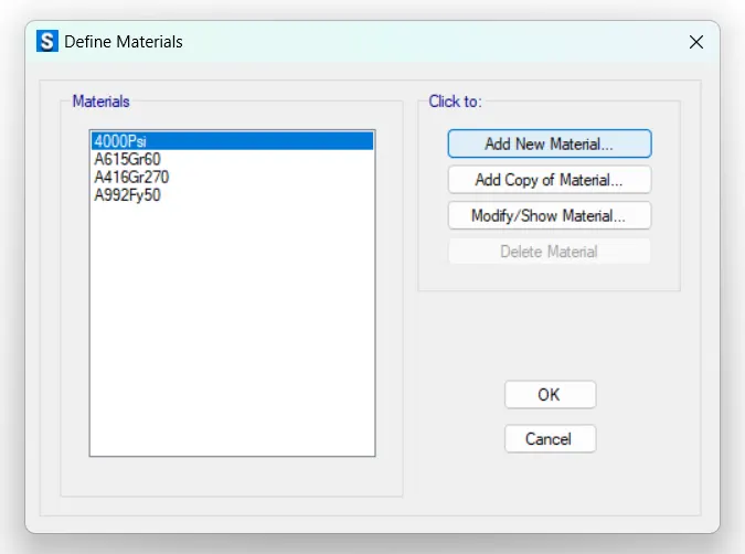
Where we create the required materials as shown.
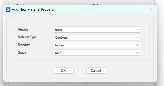
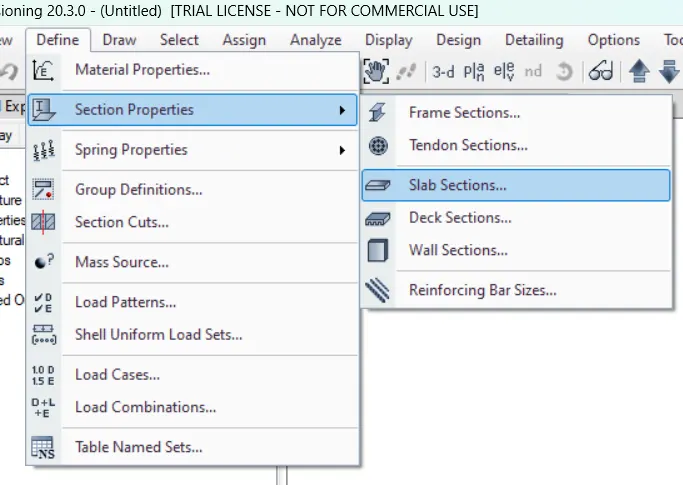
After the definition of the materials we have to define the sections.
Where we go to Define Tab>Section Properties>Slab Sections...
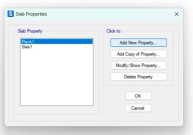
Where we continue with the clicking of Add New Property... in the Slab Properties Tab.
We then create the required slabs as shown.
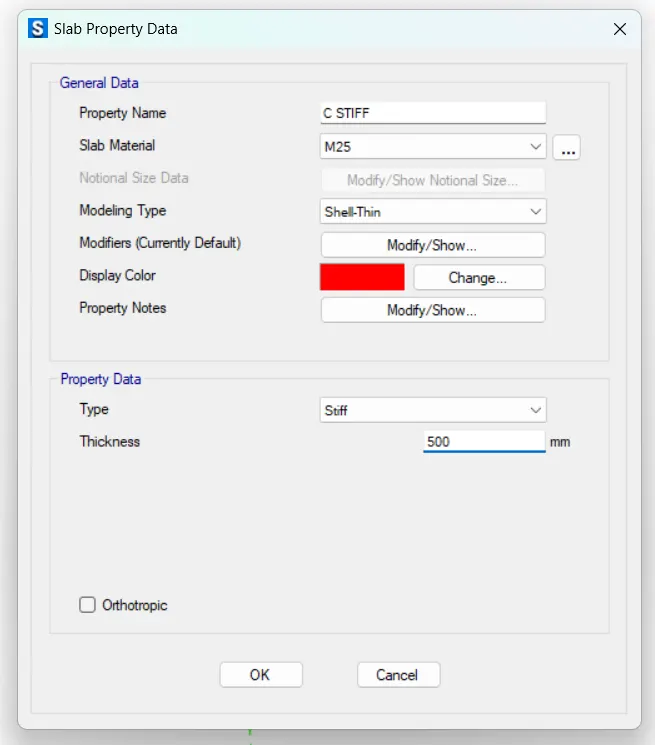
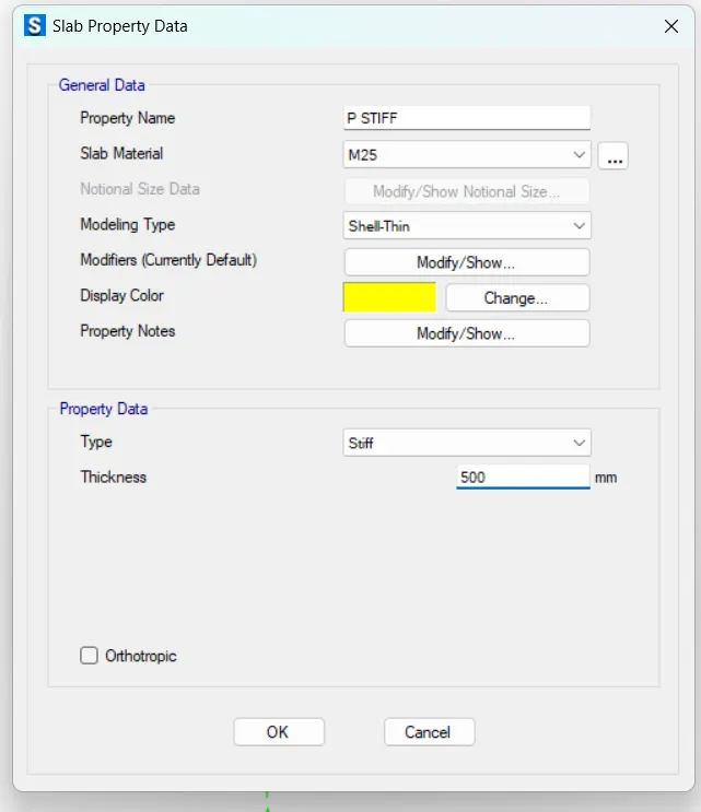
The most important thing to be done in the designing of the Pile Foundation is the definition of the springs.
Where to do that we go to Define Tab>Spring Properties>Point Springs...
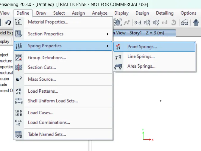
We then create a spring.
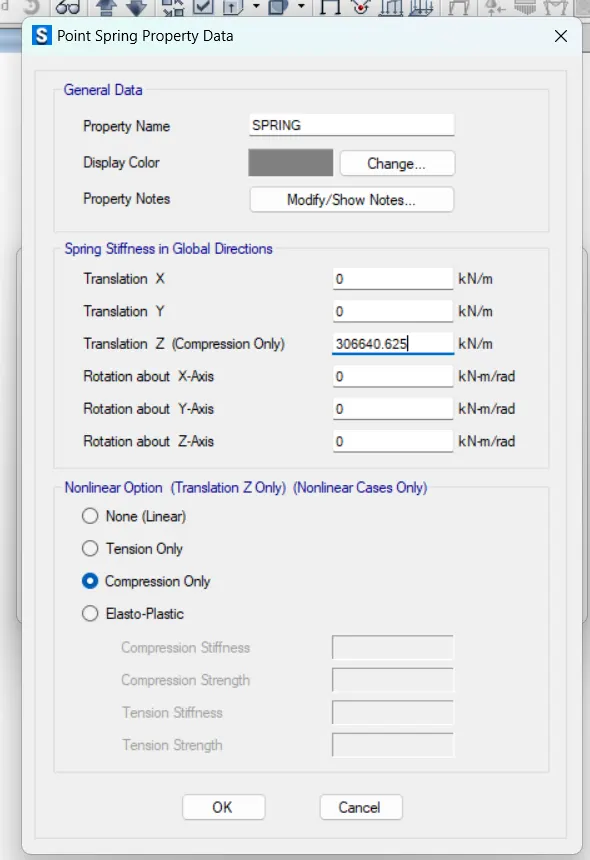
Then we continue with the creation of the loads.
For which we go to Define Tab>Load Patterns...
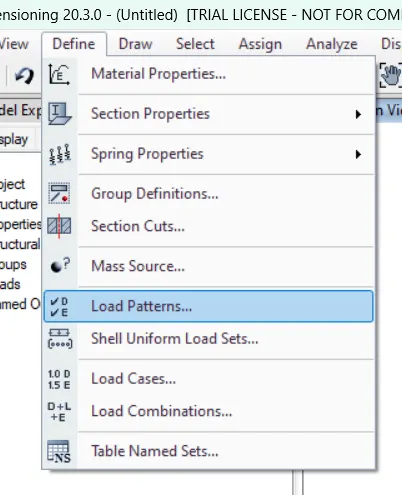
We add the Dead Load and Live Load in Define Load Patterns Tab.
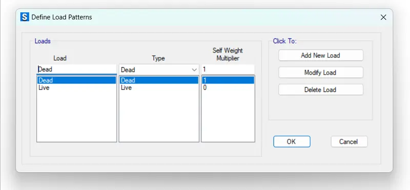
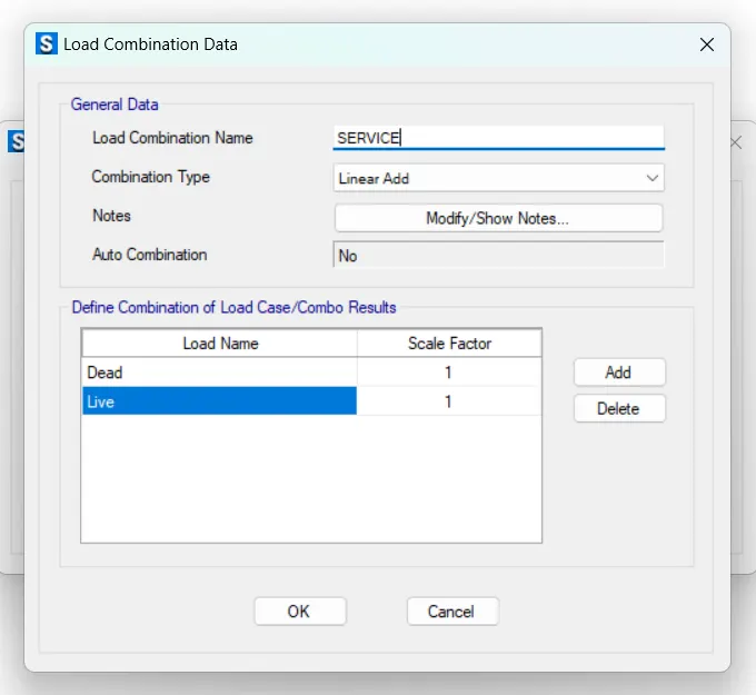
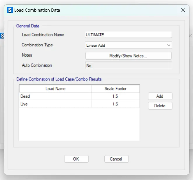
We then set the combinations for the loads created,for which we go to Define Tab>Load Combinations...
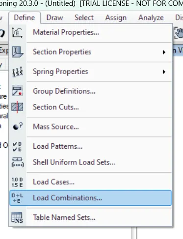
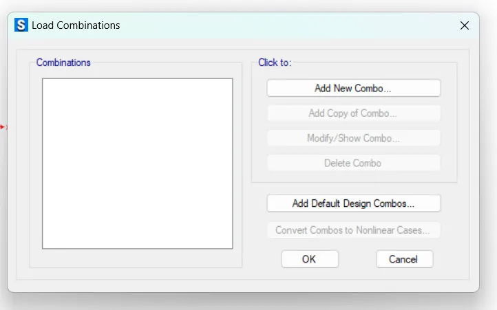
We then add 2 new combinations as shown.
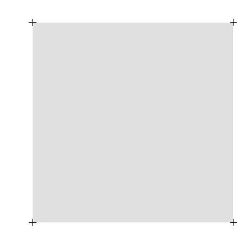
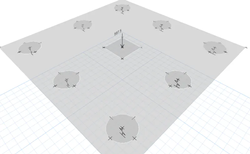
After this,we draw the Pile Cap.
We then assign the points for the pile and column positions.
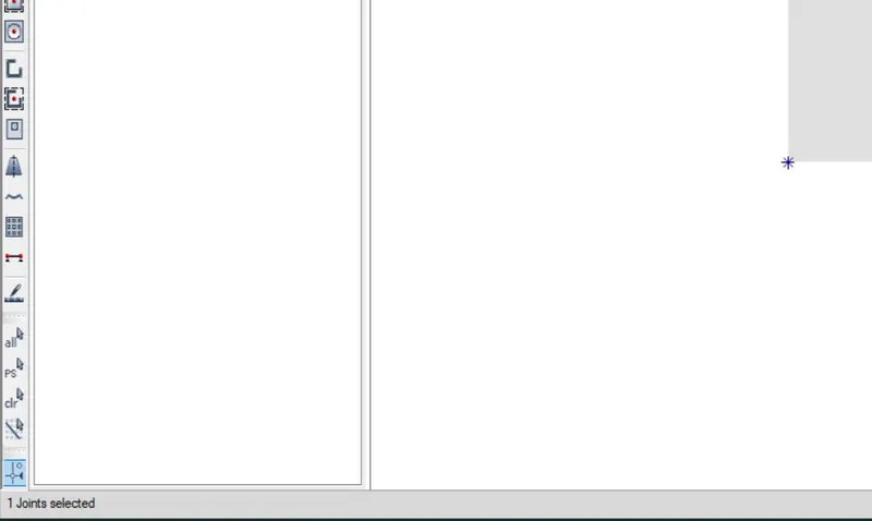
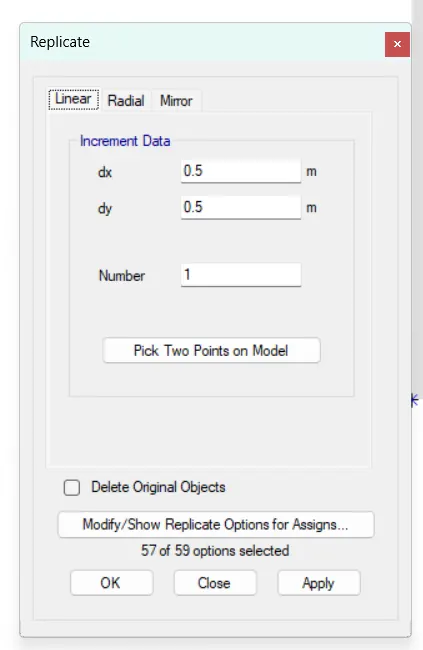
Where we use the Replicate option to do this.
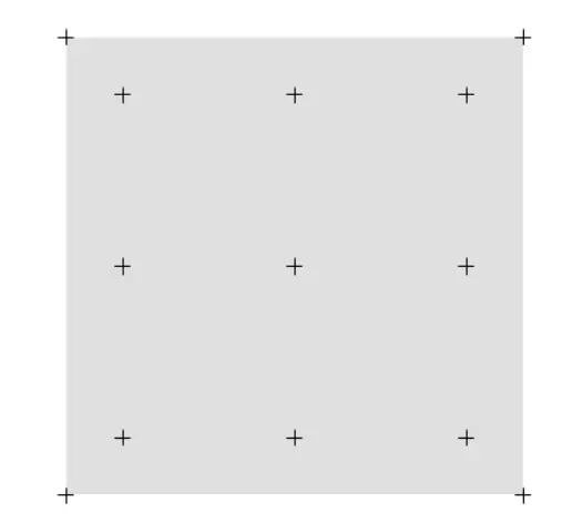
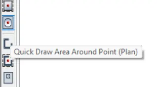
After the creation of the points we have create the areas for the column and piles,we use the option of Quick Draw Area Around Point(Plan).
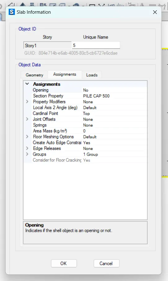
We even verify wheather the slab is of required property or not.
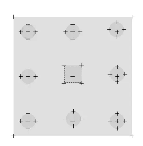
Where we then assign the springs to the piles.
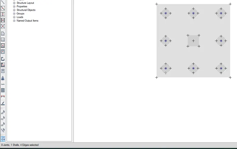
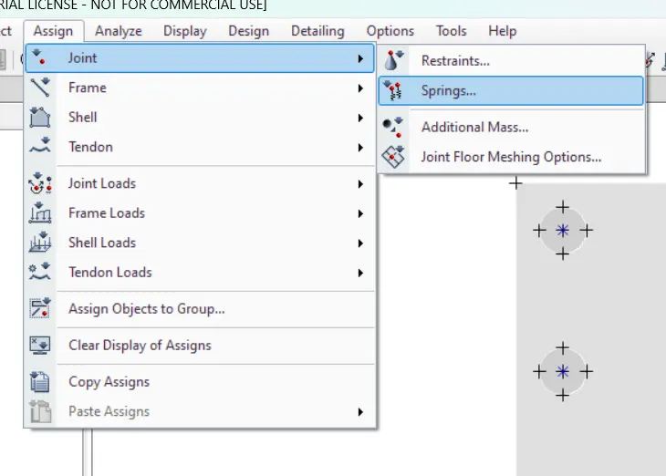
Where after the selection of the points,we go to Assign Tab>Joint>Springs...
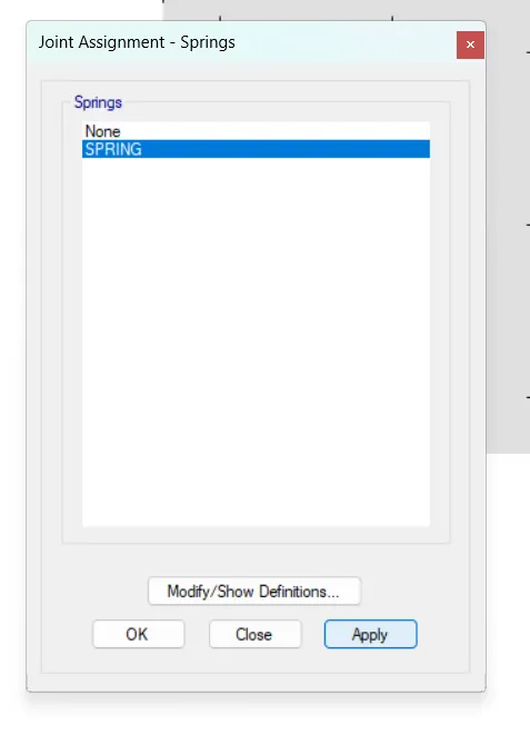
And select the created spring.
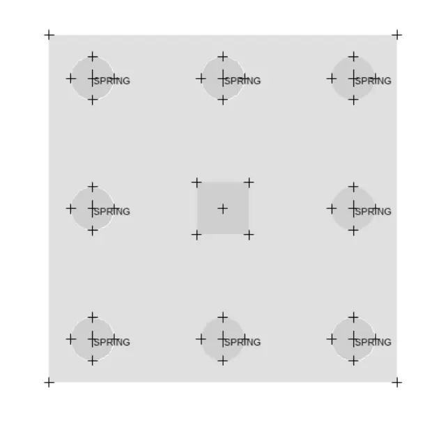
We then assign the loads to the column.
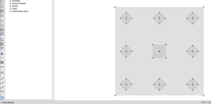
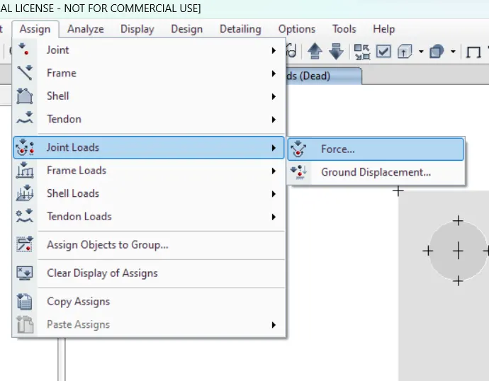
Where after the selection of the point,we go to Assign Tab>Joint Loads>Force...
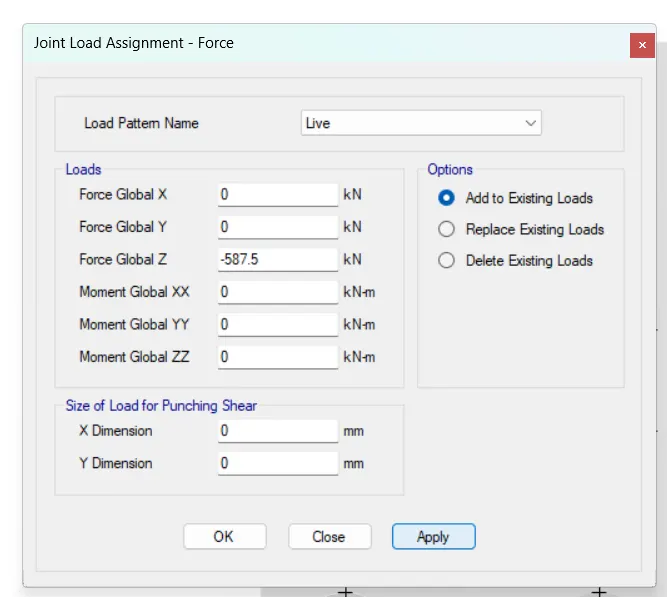
Where we give the required value for the load for different types.
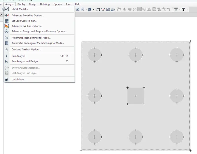
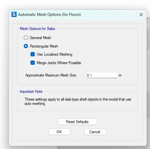
We then go with an important step i.e., set up of a mesh for the equal distribution of load.
For which we go to Analyze Tab>Automatic Mesh Settings for Floors...
We then analyze the model.
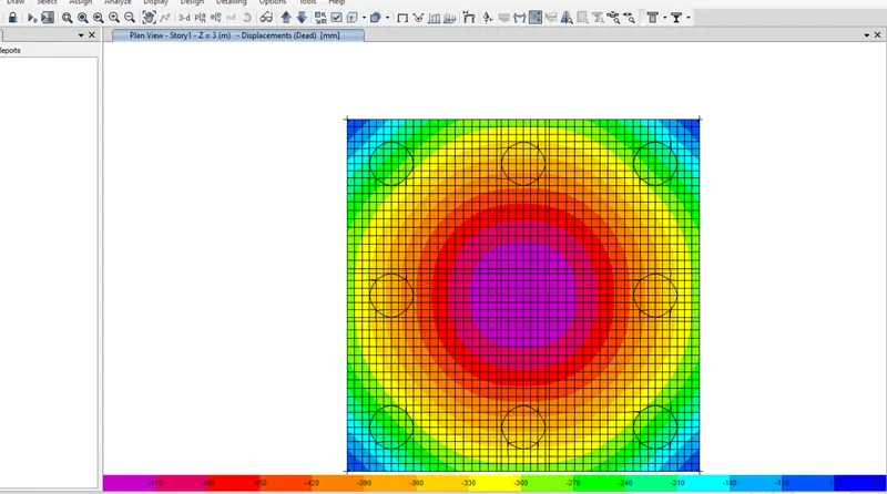
Settlement
The settlement we get is within the limit.
Punching Shear
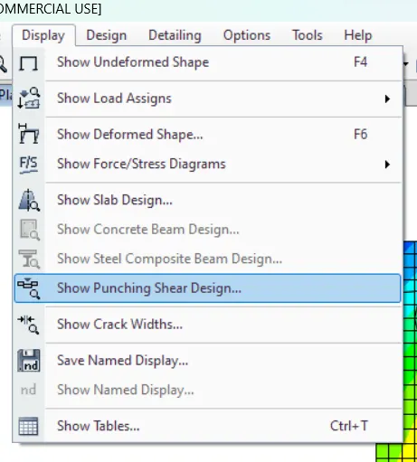
We then check for the Punching Shear,for which we go to Display Tab>Show Punching Shear Design...
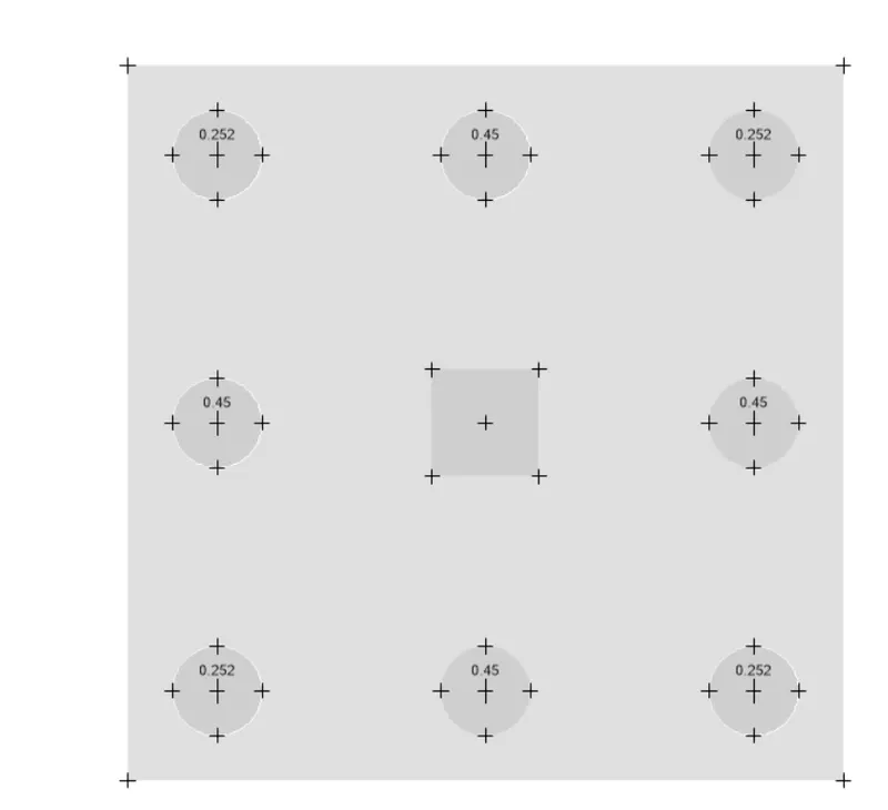
Where we can find the values within the limit of 1.
Individual Pile Load
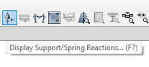
We then check for the load taken by each pile,where we go to Display Support/Spring Reactions...
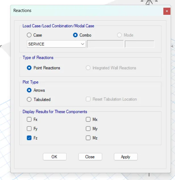
Then we select the load and check the values.
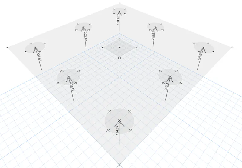
Where the load taken by individual pile is also good as per the consideration.
Reinforcement
Before getting the load,we have to draw the design strips,where we go to Draw Design Strips.
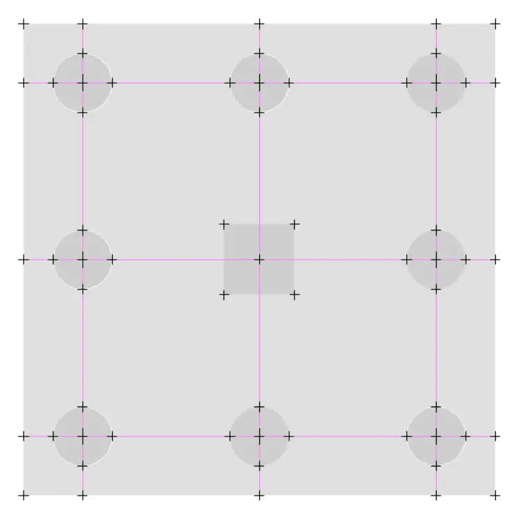
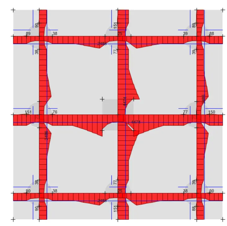
Basing upon the value from the SAFE software,we design the reinforcement.
We choose the higher value for the Bottom Reinforcement.
4474 sq mm/(3.14 X 8 X 8)=22.26=>23 bars
4000/23=173.91 mm
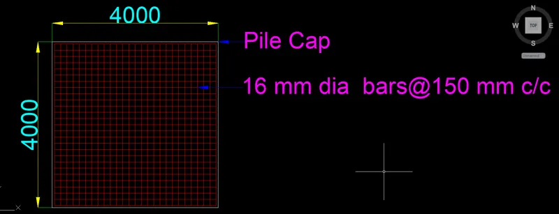
So,we provide 16 mm bars@150 mm c/c.