Foundation Design using SAFE
AIM
Model the isolated footing provided in week 11 challenge on SAFE. Analyze and design it to verify the size, depth and steel provided as per calculations.
INTRODUCTION
Here we are analyzing the footing modeled in challenge 11
The footing is analyzed using ‘Safe’
CSI SAFE (Slab Analysis by the Finite Element Method) is the best tool for designing concrete slabs and foundations by the Computer and Structures
PROCEDURE
Required data
Square footing of column size 400x400
Compression axial load for the load combination of(1.5 DL+1.5 LL) is 2000 KN
The safe soil bearing capacity is 150 KN/mm^2 at a depth of 2 m below E.G.L
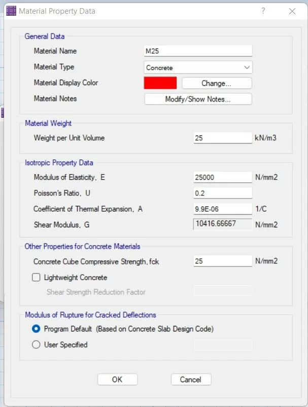
Assume M25 concrete grade
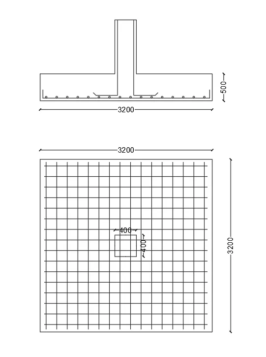
Unfactored load=2000/1.5=1333.3 kn.
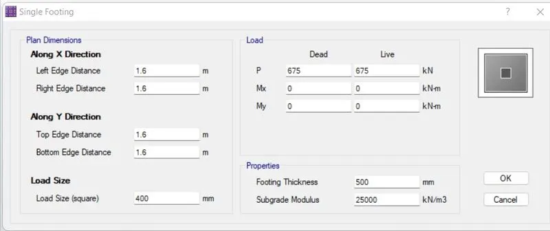
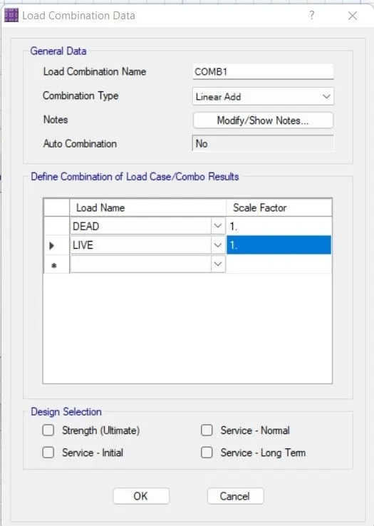
dead load Breakup=1333.3/2=666.7KN=675 KN
Live load breakup= 1333.3/2=666.7KN =675 KN
Subgrade Modulus of Soil =(Safe Bearing CapacityXFactor to Safety /maximum settlement)
Maximum settlement allowed=50mm
So, We have =150X3/0.05=9000Kn/m^3
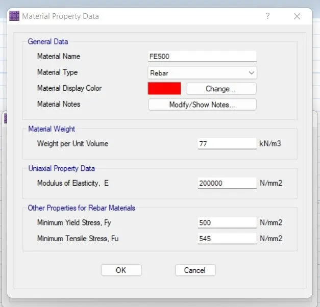
Rebar yield strength(Fy)=500N/mm^2
Rebar ultimate strength=575N/mm^2
Modulus of Elasticity of M25 concrete=25000 N/mm^2
Step 1:Open ‘Safe’
Select new model
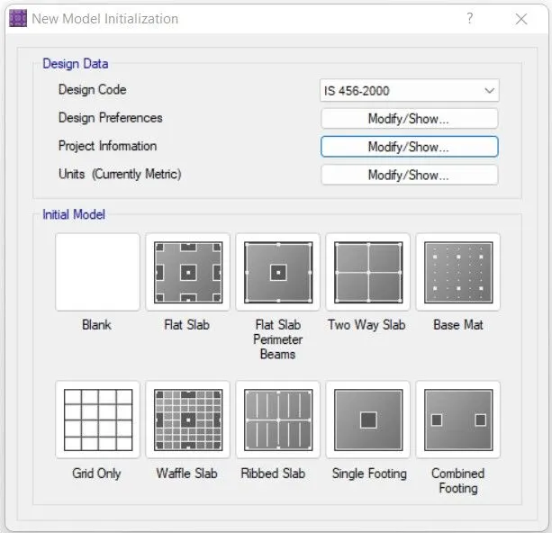
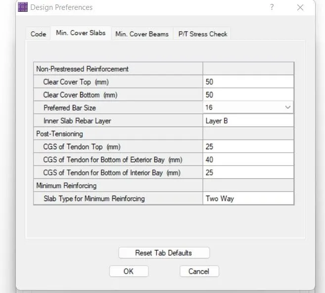
Step 2:Select single footing
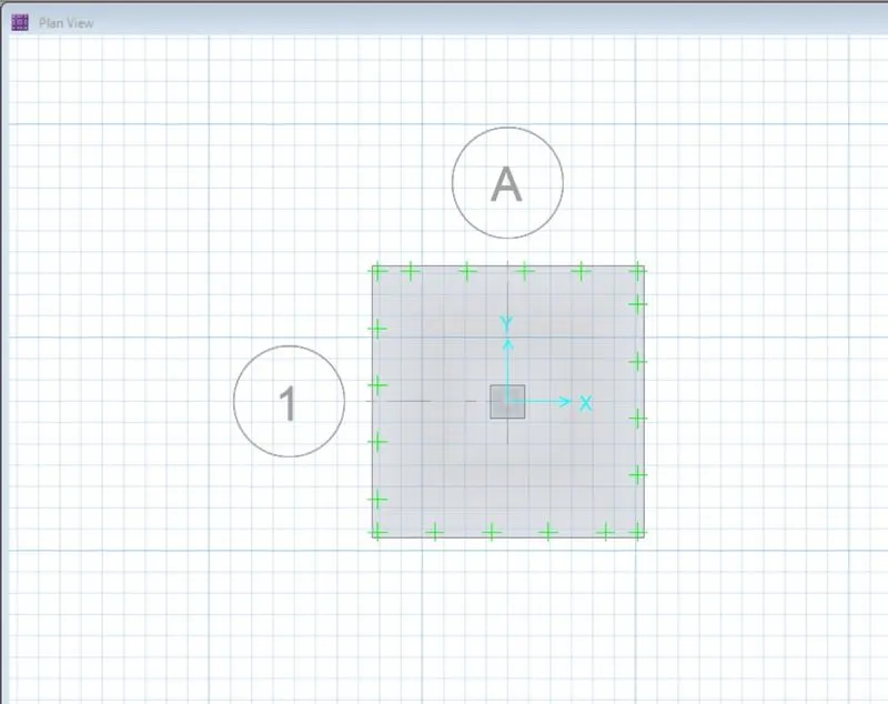
Step 3:Add materials
M25 and FE500
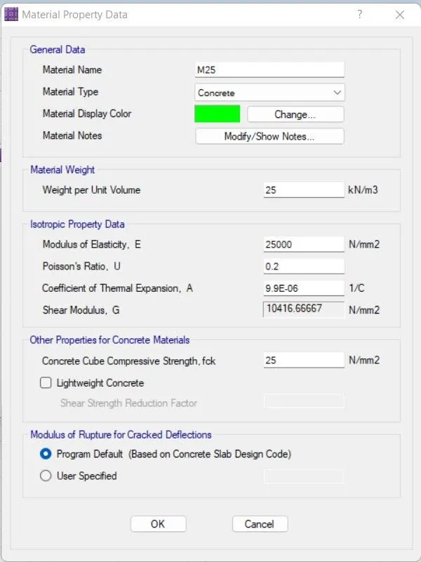
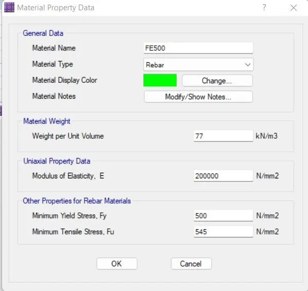
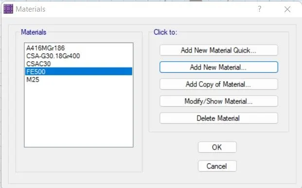
Step 4:Add slab properties
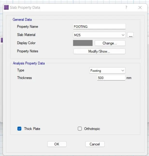
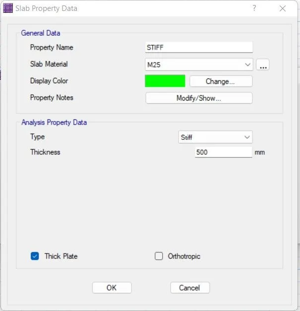
Step 5:Add soil properties
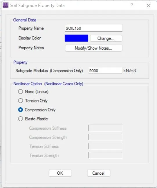
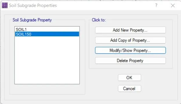
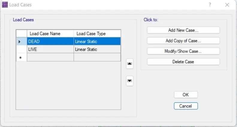
Step 6:Add load cases
Step 7:Add load combinations
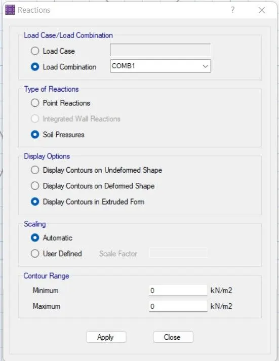
Step 8:Run the analysis
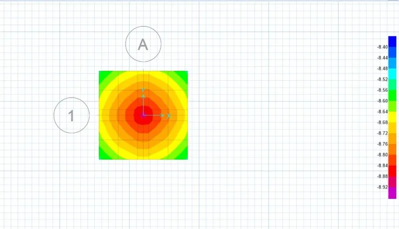
RESULT
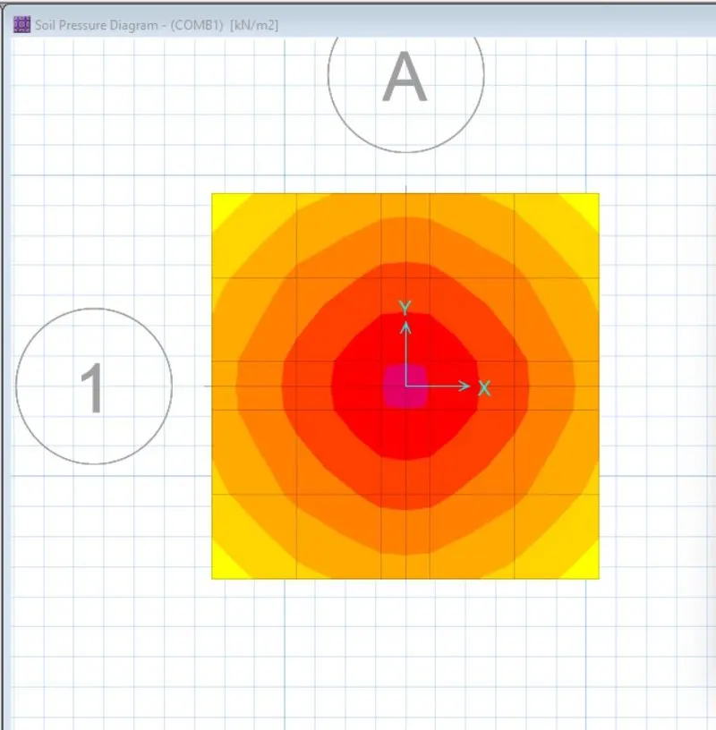
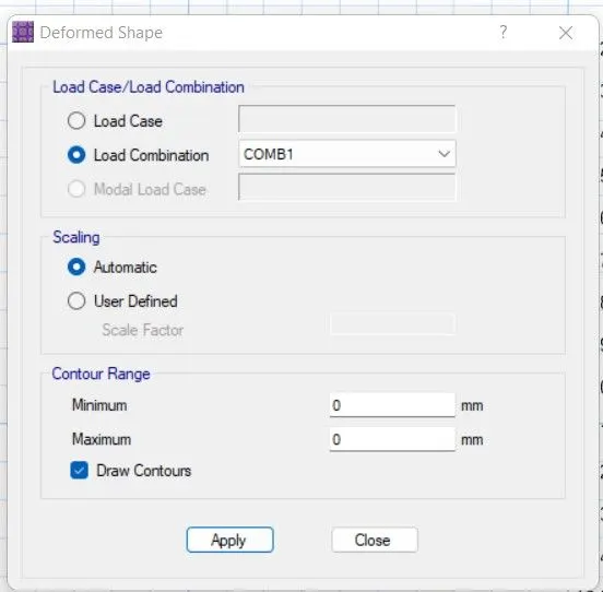
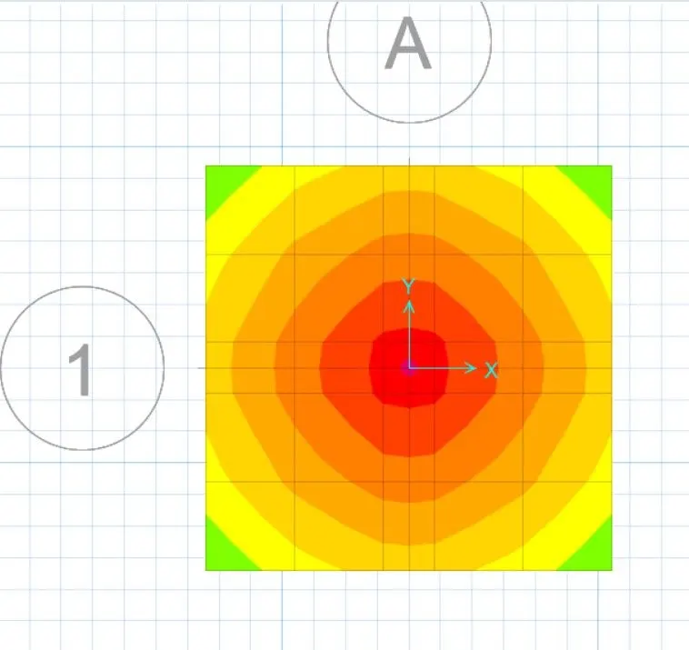
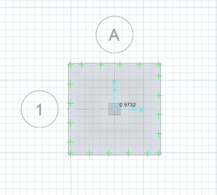
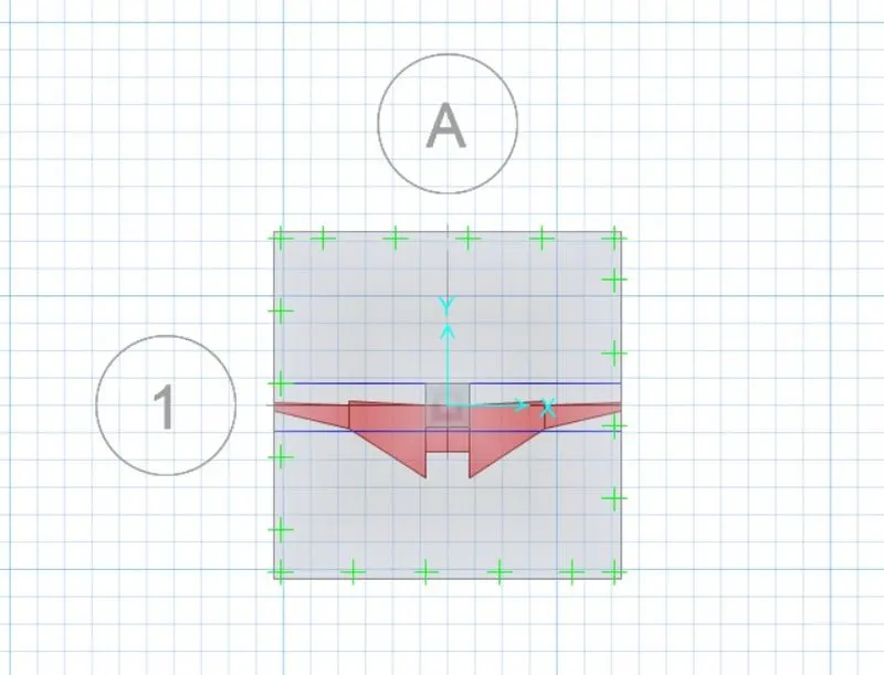
All the check is done, satisified and it is safe
AIM
A column of size 600x600 carrying an unfactored gravity load (DL+LL) of 1175 KN is to be supported on the pile cap, which ultimately transfers load to the piles underneath. Piles of 16 meters length and 500 mm diameter are to be used. Each pile has a load carrying capacity of 200 KN. Model, analyze and design the pile cap on SAFE to evaluate the following:
- Pile group to be used
- Depth of pile cap
- Longitudinal steel on top and bottom face in both directions
INTRODUCTION
The footing is analyzed using ‘Safe’
CSI SAFE (Slab Analysis by the Finite Element Method) is the best tool for designing concrete slabs and foundations by the Computer and Structures
Codes reffered IS 456-2000,IS 2911 (part 2) and SP 34
PROCEDURE
Required Data
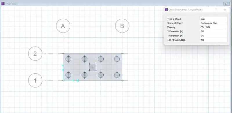
Column size= 600 x 600 sq.m
Unfactored Gravity load = 1175 KN
Length of the pile to be used = 16 meters
Diameter of one pile = 500 mm
Pile Bearing Capacity = 200KN
Unfactored load=1175 KN
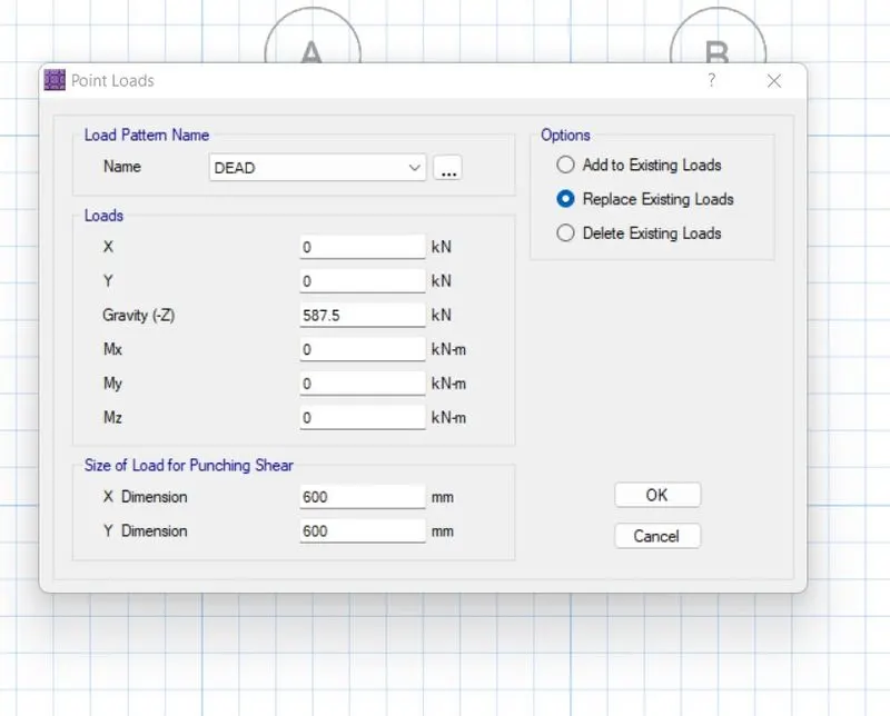
Dead load Breakup=1175/2=587.5 KN
Live load Breakup=1175/2=587.5 KN
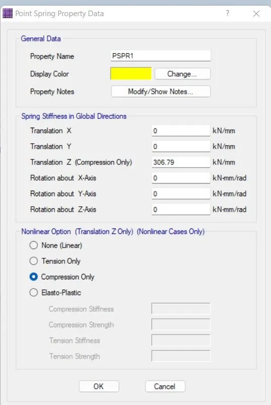
Point Spring of Pile= A *E /L=
area of one pile=(πxd^2)/4=(π*500^2)/4=196349.5 mm^2
E=5000 * Fck^0.5=5000*25^0.5=25000N/mm2
L=16000
Point Spring of Pile= A*E /L=196349.5X25000/16000=306796 N/mm
Rebar yield strength(Fy)=500 N/mm^2
Rebar ultimate strength=575 N/mm^2
Elastic modulus of M25 concrete= 25000 N/mm^2
Number of piles required= Unfactored load with self weight addition/individual pile
capacity
=1175*1.1/200=6.5
consider 8 piles for symmetric placement of piles under pile cap
Considering C/C distance between piles= 3 * pile diameter=3*500=1500mm
Edge distance from pile center= 1 * pile diameter=1*500=500mm.
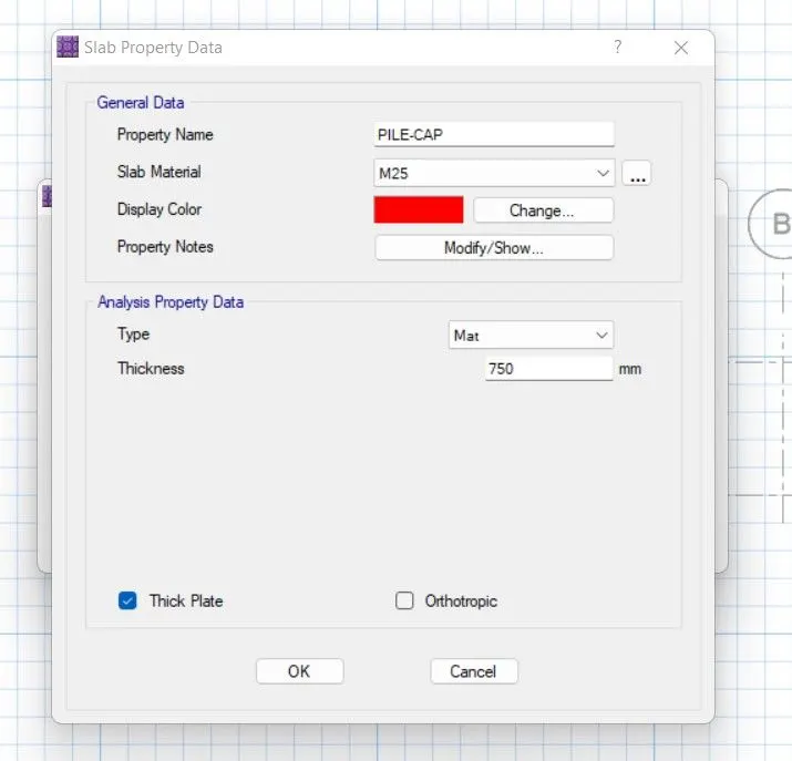
Assume pile cap depth=500mm.
Step 1:Open safe
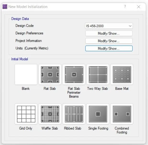
Step 2: Select grid only
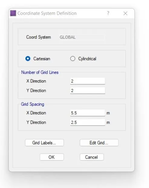
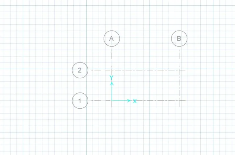
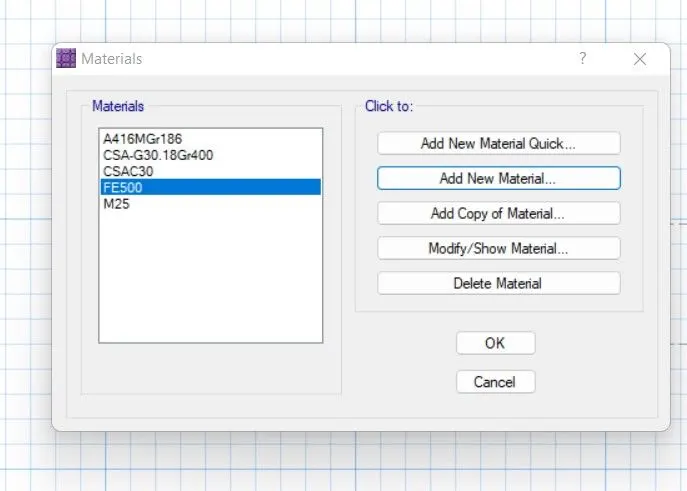
Step 3:Add materials
M25 and FE500
Step 4:Add slab properties
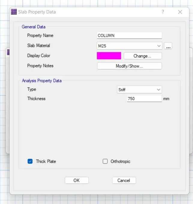
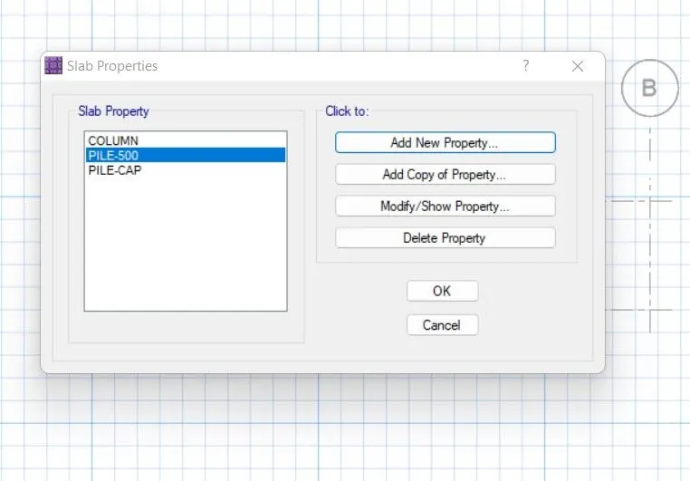
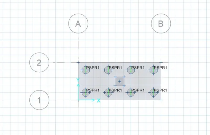
Step 5:Draw the pile cap
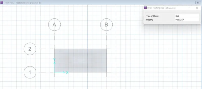
Step 6:Draw the points
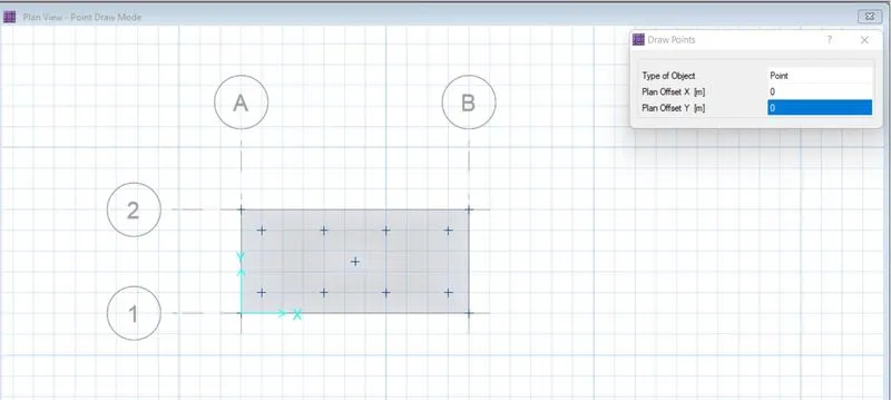
Step 7:Draw the pile
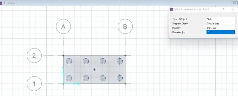
Step 8:Draw column.
Step 9:Assign point pring
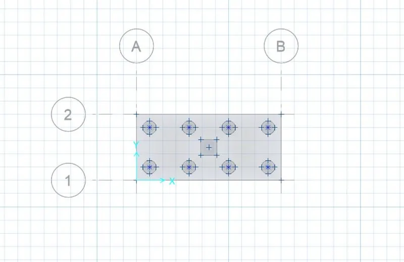
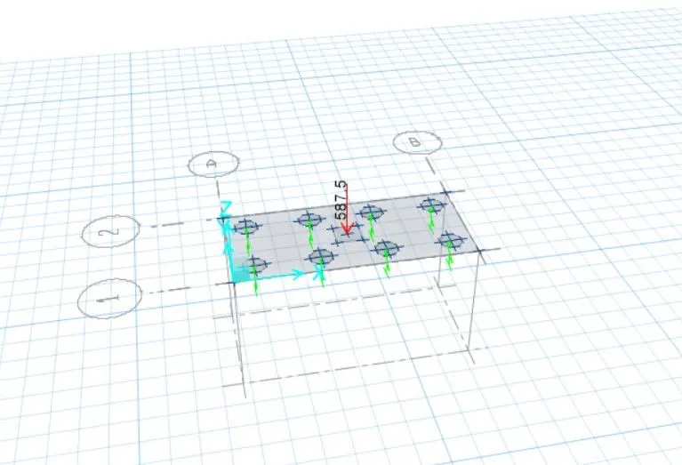
Step 10:Assign point load to the column
Step 11:Run analysis
RESULTS
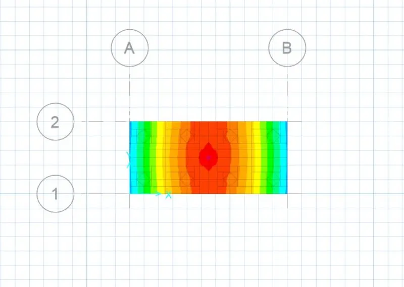
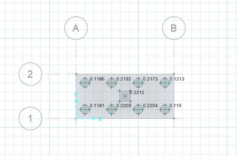
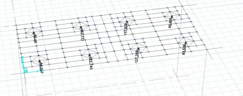
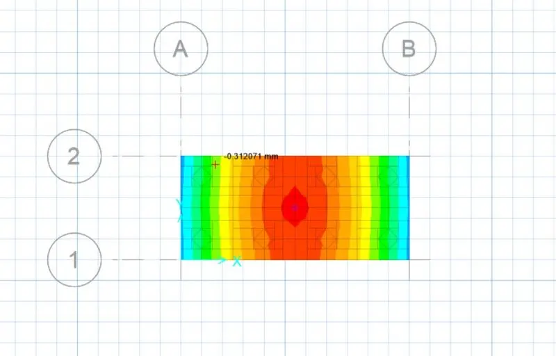
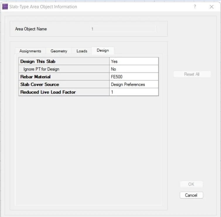
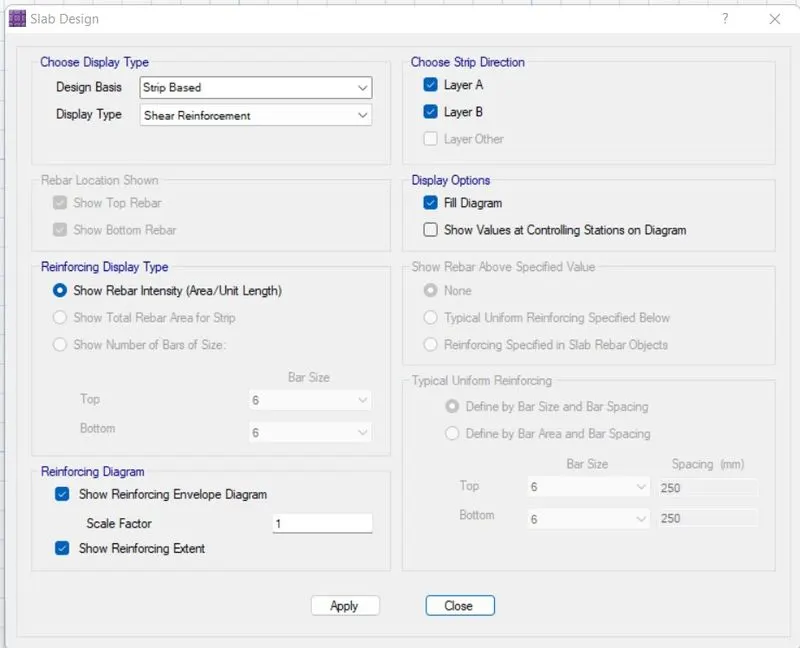
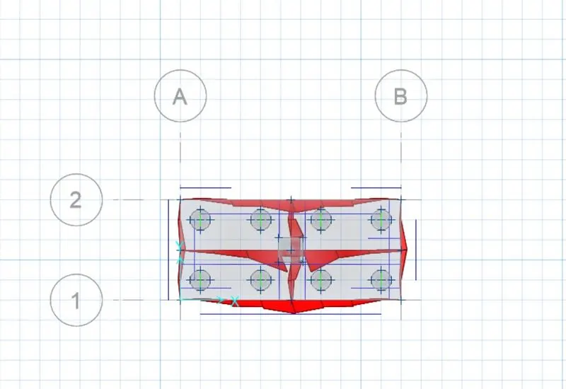
All the check is done, satisified and it is safe