Flow over an airfoil
AIM:- To determine the drag force and lift force for a NACA0017 airfoil at different angle of attack(A.O.A)
OBJECTIVE:- Model the flow over a NACA0017 airfoil and,
For the angle of attack 0,2,4,6,8,10 compare the lift and the drag forces.
THEORY:-
An airfoil is a surface designed to obtain a desirable reaction from the air through which it moves. Thus, we can say that any part of the aircraft which converts air resistance into a force useful for flight is an airfoil. The blades of a propeller are so designed that when they rotate, their shape and position cause a higher pressure to be built up behind them than in front of them so that they will pull the aircraft forward. The model of a wing gives an excellent example of streamlines around airfoil.
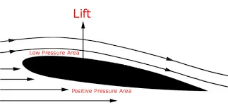
Although the top surface of the conventional wing profile has greater curvature than the lower surface, the principal thing is the larger density of streamlines above the wing. The larger density of streamlines means the greater velocity of air.
The role of the wing is to generate lift
- Lift is perpendicular to the incoming flow
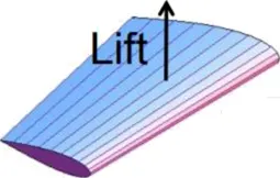
Lift creation can be described in two ways:
- Pressure differential: The air pressure on the bottom surface of the wing is higher than the air pressure of the top This pressure difference creates a net force upwards
- Newton’s third law: The wing pushes air As a consequence, the air itself pushes the wing upwards.
Either way, the laws of conservation apply: mass, momentum and energy.
LIFT:-
Lift, or downforce as it’s known in the motor racing world, is the force generated perpendicular to the direction of travel for an object moving through a fluid [gas or liquid]. The same effect occurs when a fluid moves over a stationary object, such as an airfoil in a wind tunnel. Airfoils are the most efficient shapes found so far that can generate lift while at the same time minimizing drag.
DRAG:-
Drag is an unavoidable consequence of an object moving through a fluid. Drag is the force generated parallel and in opposition to the direction of travel for an object moving through a fluid.
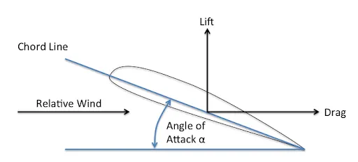
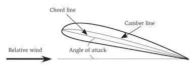
In fluid dynamics angle of attack (AOA) is the angle between a reference line on a body (often the chord line of an airfoil) and the vector representing the relative motion between the body and the fluid through which it is moving . It is an angle between the body's reference line and the oncoming flow.
FORCE AND COEFFICIENT:-
The dimension less lift coefficient and drag coefficient are defined as: Lift Force (FLI = CL . A . q
Drag Force (FDI = CD . A . q
Where,
L = dimension less lift coefficient
D = dimension less drag coefficient
A = reference area of an airfoil or wing
q = 1/2 rho V2 = free stream fluid dynamic pressure from Bernoulli's equation:
Where,
rho = free stream fluid density V = free stream fluid speed
PROCEDURE:-
Ckick on new part then go to insert then curve then with the help of browse button select the text data file which contains the data for the airfol and click ok.
A curve will be generated. Then select the plane click on curve and then click on convert entity button from the toolbar and make a line at the open ends to make it a closed geometry. We will get the sketch of the airfoil now.
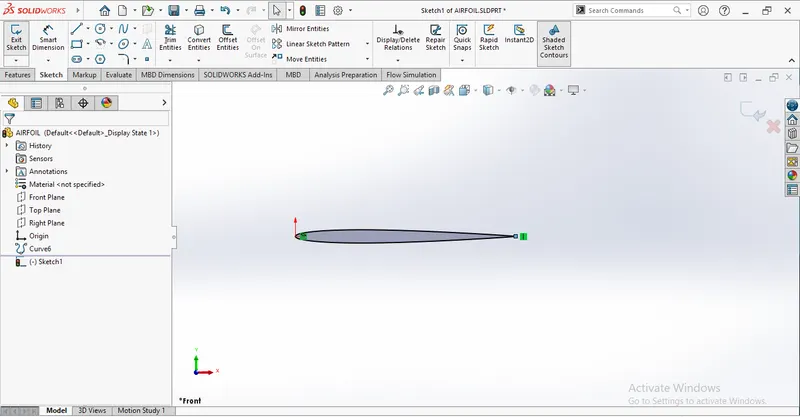
Now we can change the angle of attack by clicking on rotate entity then selecting the curve and the line drawn at the end and selecting origin as the point for changing the angle, then we can give angle whhich we want as 0,2,4,6,8,10 in different cases.
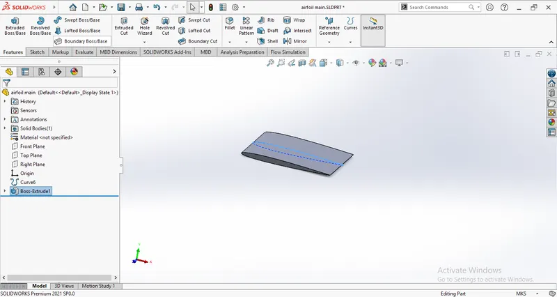
Select the curve sketch and extrude it using the midplane to 1m.
FLOW SIMULATION:-
Click on wizard and name the project as airfoil analysis and click next and select tthe following options.
Analysis type- external
Total analysis time=5s
Output step time=1s
Fluid=air
Flow type= laminar and turbulent
Wall condition= Adiabatic
Velocity in X direction=600m/s
Finish.
Now, right click on computational domain select the 2D simulation.
Adjust the domain in such a way that the length and height of the domain at inflow should be 5 times the chord length and distanceat outflow should be 10-15 times the chord lengthh.
Right click on goals and provide-
Global goal= Force(X), Force(Y), Friction force(X), Friction force(Y) and
Surface goal= Force(X) reffered as drag force and Force(Y) reffered as lift force [Bt selecting the surface].
Insert the cutplots for velocity and pressure contours.
Click on Run.
RESULTS:-
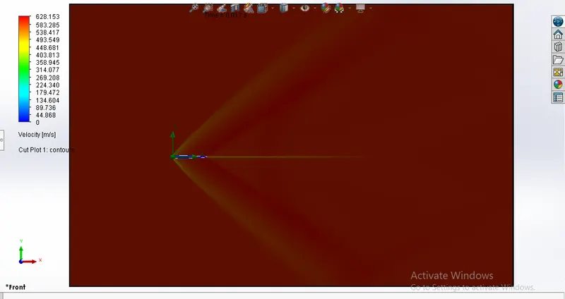
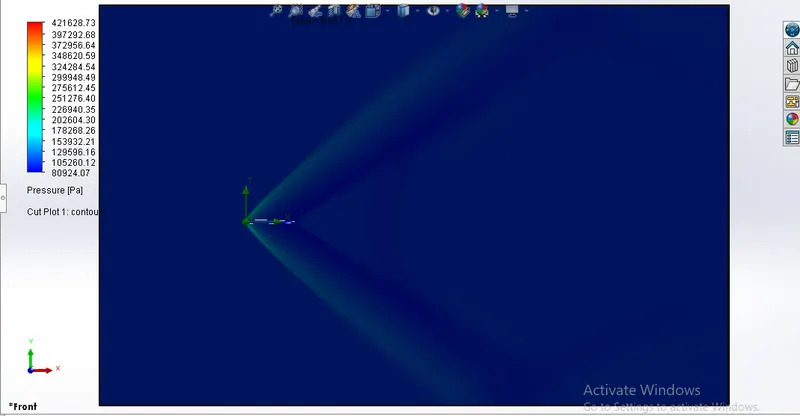
For angel of attack 0 degree-
Velocity contour
Pressure contour
Drag Force and Lift Force

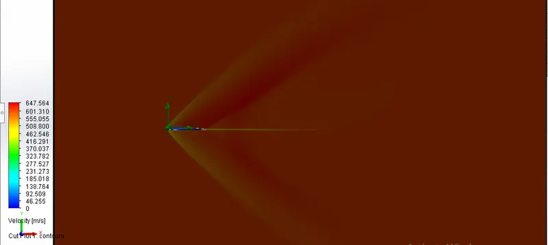
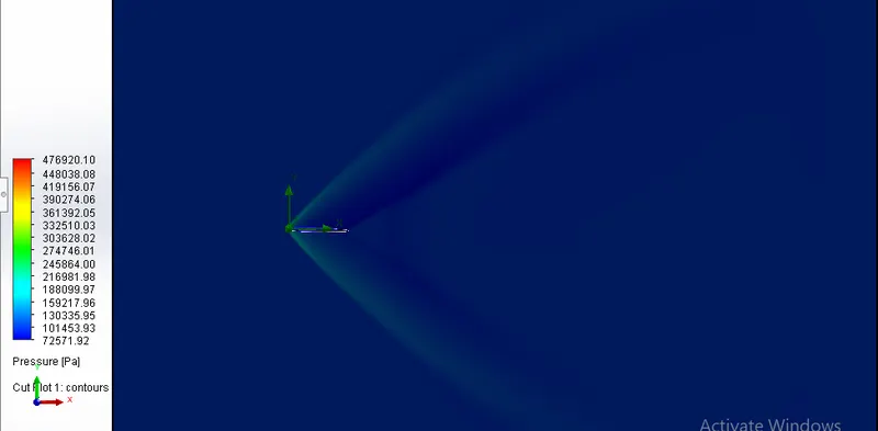
For angle of attack 2 degree:
Velocity contour
Pressure contour
Drag force and Lift force:

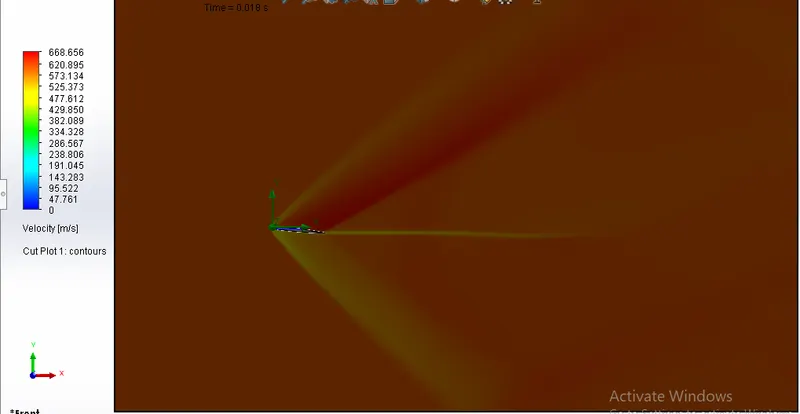
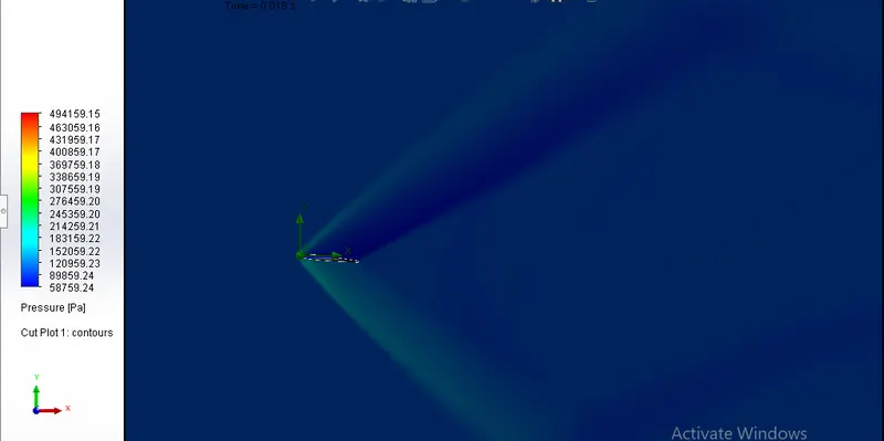
FOR ANGLE OF ATTACK 4 DEGREE:
Velocity Contour
Pressure contour
Drag Force and Lift Force

FOR ANGLE OF ATTACK 6 DEGREE:
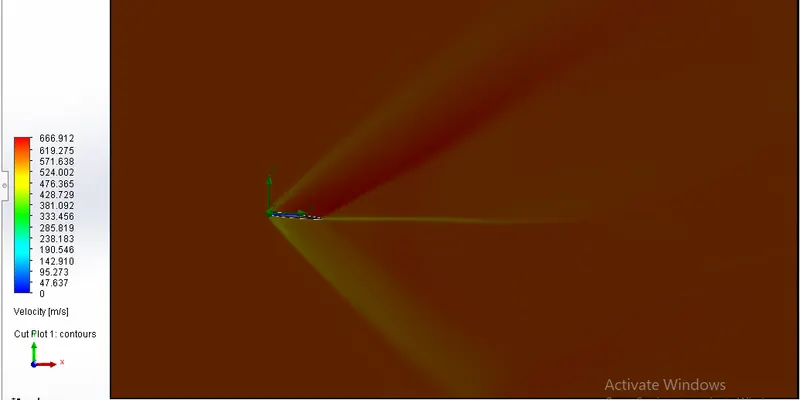
Velocity Contour:
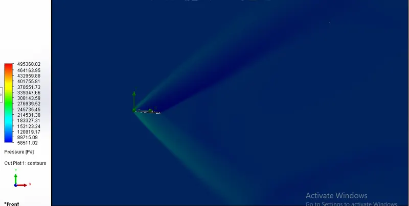
Pressure Contour:
Drag Force and Lift Force:

FOR ANGLE OF ATTACK 8 DEGREE:
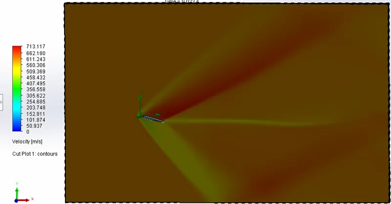
Velocity contour:
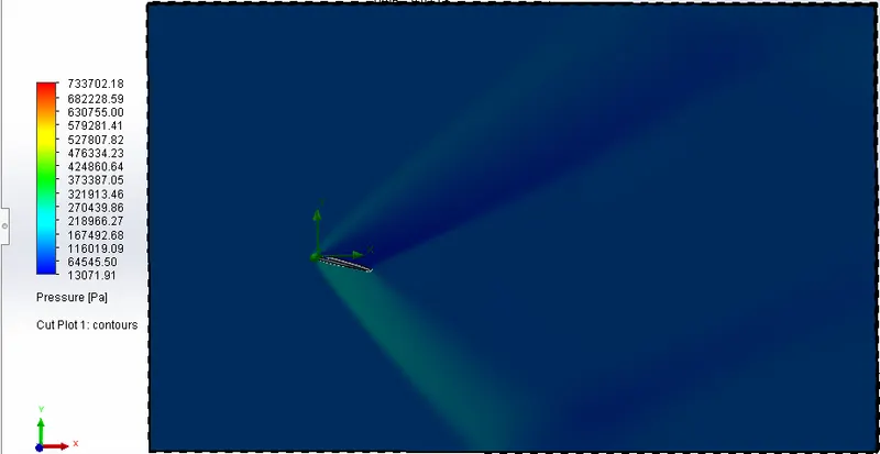
Pressure contour:
Drag Force and Lift Force:

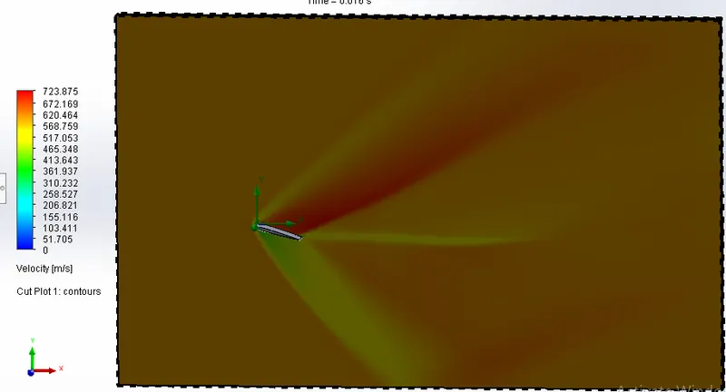
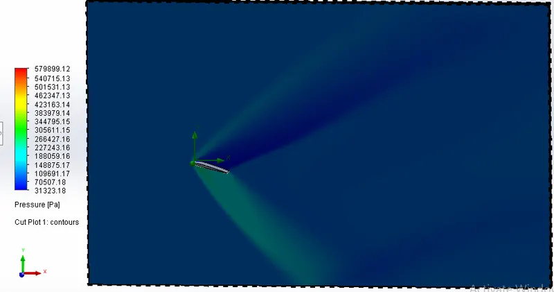
FOR ANGLE OF ATTACK 10 DEGREE:
Velocity Contour:
Pressure Contour:
Drag Force and Lift Force:

CONCLUSION:
The average drag force and lift force by analysing the airfoil with different angle of attacks 0,2,4,6,8,10 can be seen as follows:
AVERAGE DRAG FORCE:-
| ANGLE OF ATTACK | AVG. DRAG FORCE(N) |
| 0 | 1531.313 |
| 2 | 1667.213 |
| 4 | 2728.214 |
| 6 | 2724.564 |
| 8 | 8197.054 |
| 10 | 10952.370 |
AVERAGE LIFT FORCE:-
| ANGLE OF ATTACK | AVG. LIFT FORECE(N) |
| 0 | 5.740 |
| 2 | 4093.663 |
| 4 | 12029.460 |
| 6 | 12025.832 |
| 8 | 27470.235 |
| 10 | 31583.241 |
On the basis of these tables we can conclude that-
1. On increasing the angle of attack the drag and lift force increases.
2. The stall angle can not be achieved because the lift force is increasing when it will become constant as we keep on increasing the AOA then we will get our stall angle and the max lift force.
3. We can see that after AOA 8 the max velocity of air inreased at a slow rate as it was increasing rapidly from 0 to 8.
4. By observing the maximum pressure we can see that it increases when tha angle of attack increases but at AOA 10 the max pressure at the airfoil decreases.
5. As the angle of attack increases the velocity distribution on upper and lower surface of airfoil also changes.
6. As the AOA increases the we can see that a pressure region is created under the surface of airfoil which further helps in increassung the lift force of the airfoil.