Flow over a cylinder
AIM:- To perform external flow simuation over a cylinder with different velocities corresponding to their Reynolds number.
OBJECTIVE:- 1. Calculate Reynolds number for different inlet velocities
2. Perform external flow simulation on cylinder with different inlet velocities corresponding to their reynolds number
3. Obtain velocity and pressure conyours.
4. Compare the results and make conclusion.
THEORY:-
Computational Fluid Dynamics (CFD) is the simulation of fluids engineering systems using modelling (mathematical physical problem formulation) and numerical methods (discretization methods, solvers, numerical parameters, and grid generation etc.)
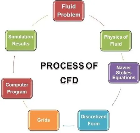
To solve a fluid problem first we should know the physical properties of the fluid by using fluid mechanics. Then we can use mathematical equations to describe these physical properties. this is Navier stock equation and it is also known as the governing equation of CFD. As this equation is analytical we can understand it and solve them on a peice of paper. But if we want to solve this on computer we have to translate it to discritisized form. THese translators are known as finite element or finite eleent analysis.
As per the increase in the technology and advancement there is so much of importance of CFD method which can be described as follows:
1. The most important thing is it is cheaper in cost.
2. It takes a short time to solve the problems.
3. It can be used by any scale industry.
4. It is safe to use rather then the physical experiments.
Now as for this challenge our main focus is on Reynolds number.
REYNOLDS NUMBER:
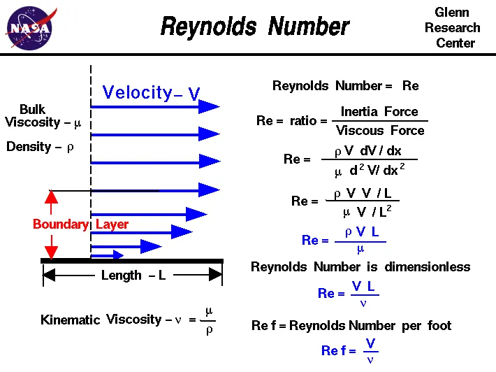
The reynolds number is the ratio of inertial forces to viscous forces within a fluid which is subjected to relative internal movement due to different fluid velocities. It is an important dimensionless quantity in fluid mechanics used to help predict flow patterns in different fluid flow situations.
The reynolds number is denited by (Re) and is defined as D
Re= ρuD/μ where ,
ρ is density of fluid (kg/m3)
u is the flow speed (m/s)
D is diameter of tube (m)
μ is dynamic viscosity of the fluid .
CALCULATION:
The calculations which have to be done for the is project is as folllows-
Reynolds number can be calculated by putting the value of air as
ρ=1.225kg/m3
D= 0.05m
μ= 1.81*10-5kg/ms
For case 1, Speed of flow (u)=10m/s ,
then , Re= 33840
For case 2 , Speed of flow (u) = 12m/s,
then, Re = 40607
For case 3, Speed of flow (u) = 14m/s,
then, Re = 47375
For case 4 , Speed of flow (u) = 20m/s,
then , Re= 67679
Now simulation time can be calculated as :
For case 1
Time= 1/10=0.1s
Simulation time = 2*time=0.1*2=0.2s
Step time= simulation time/10=0.2/10=0.02s
smilarly we have
For case 2
simulation time=0.16s and,
Step time = 0.001
For case 3
Simulation time= 0.14
Step time = 0.001
For case 4
Simulation time = 0.1
Step time= 0.01
All values by considering computational domain length as 1m.
PROCEDURE:
Create a circle in front plane of 0.05m diameter and 0.05 then extrude it to a length of 0.05m and then save the profile.
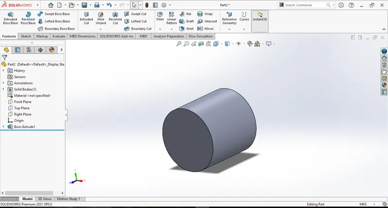
Afeter saving the profile click on the Flow simulation option.
Then click on wizrd and give the rpoject neame as Flow over cylinder and click next and select the folllowing options:
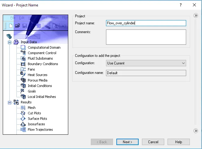
First we will not change anything fron the units we will use them as default. Now,
Analysis type- External
Fluid type - Air
Wall conditio- Adiabatic
Roughness- 0 micrometer
Velocity in X direction 10m,12m,14m,20m for 1,2,3,4 cases respectively
Then Finish.
After this a computational domain will be created where the simulation will be performed.
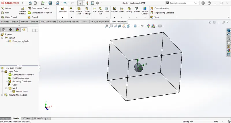
Now we can see the basic mesh by right clicking on the mesh button and then selecting show basic mesh.
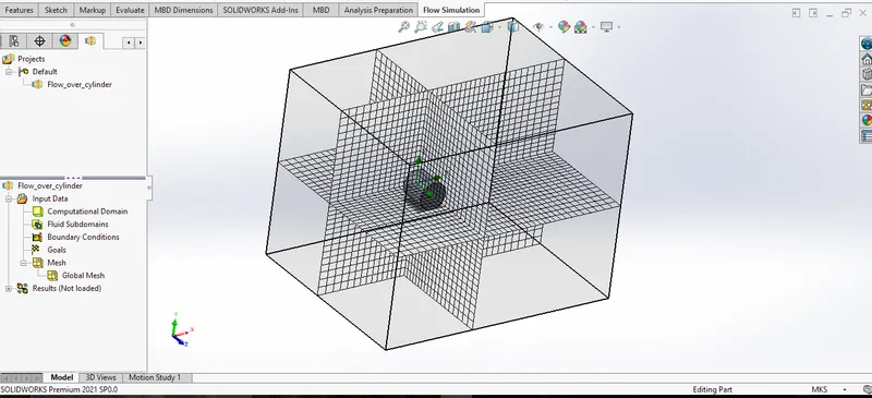
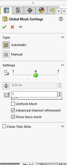
As the mesh looks fine so to have more accurate results we can change the mesh setting to 4 and select the advanced channel refinement ny selecting edit definition on global mesh.
Add two cut plots with XY planes for velocity and pressure contours and click on run to get the results.
Cut plot 1 is for velocity contour and Cut plot 2 is for the pressure contour.
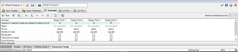
Now we will conduct a new parametric study by right clicking on flow over cylinder and slecting input parameters as the inlet velocity and output parameters as the cut plots and then will go to the scenario and copy paste the first data three times so that we can change the inlet velocities in that data as 10m/s , 12m/s, 14m/s, 20m/s as a factor of increasing the reynolds number by 20%, 40%, and 100%.
Then we click on run to get the results.
RESULTS:
Case 1: Inlet flow velocity=10m/s
VELOCITY CONTOUR
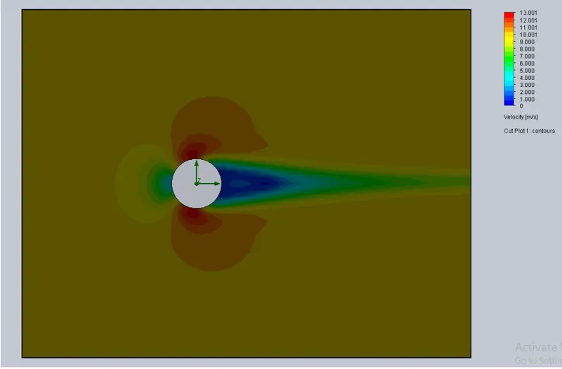
Here min=0m/s and max= 13.001m/s
PRESSURE CONTOUR
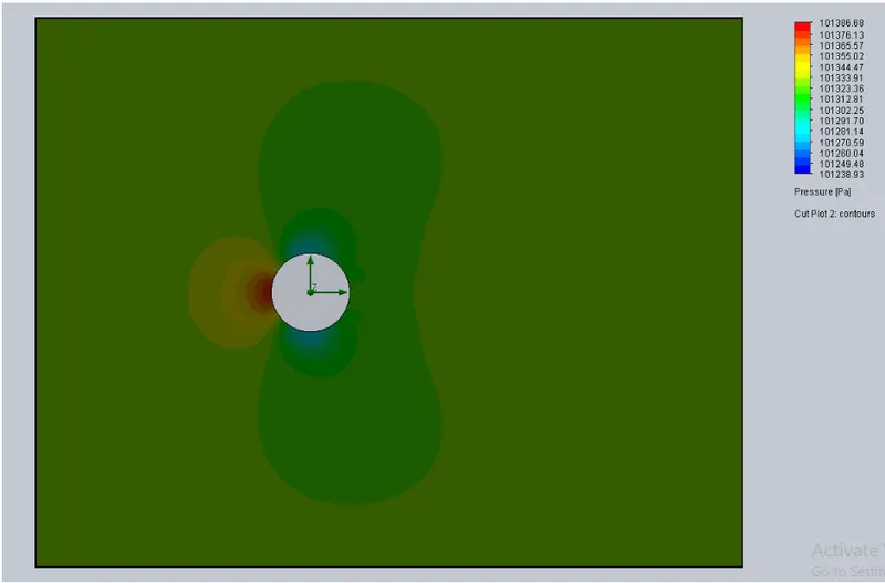
Min= 101238.93pa , Max=101386.69Pa
VELOCITY ANIMATION
PRESSURE ANIMATION
CASE 2 INLET FLOW VELOCITY=12m/s Reynolds number increased by 20%
VELOCITY CONTOUR
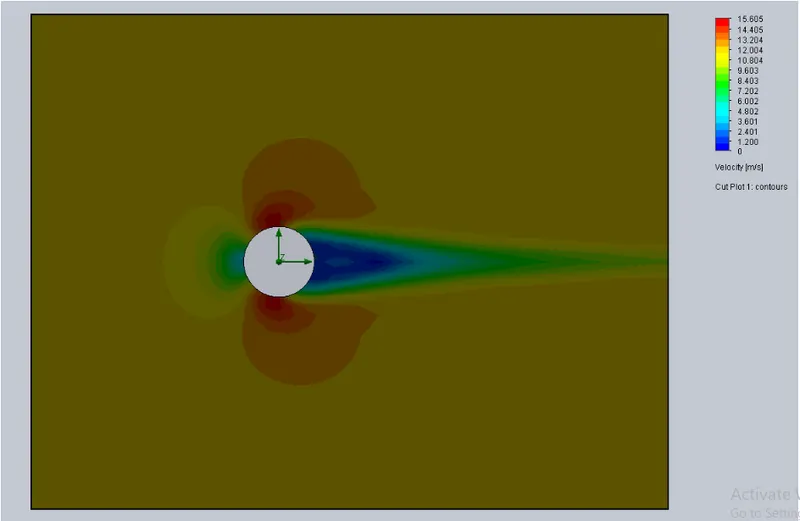
Here min=0m/s and max= 15.505m/s
PRESSURE CONTOUR
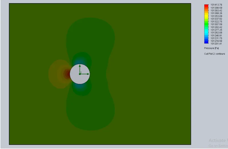
Here min=101201.41 Pa and max=101413.76 Pa
VELOCITY ANIMATION
PRESSURE ANIMATION
CASE 3 INLET FLOW VELOCITY=14m/s, Reynolds number increased by 40%
VELOCITY CONTOUR
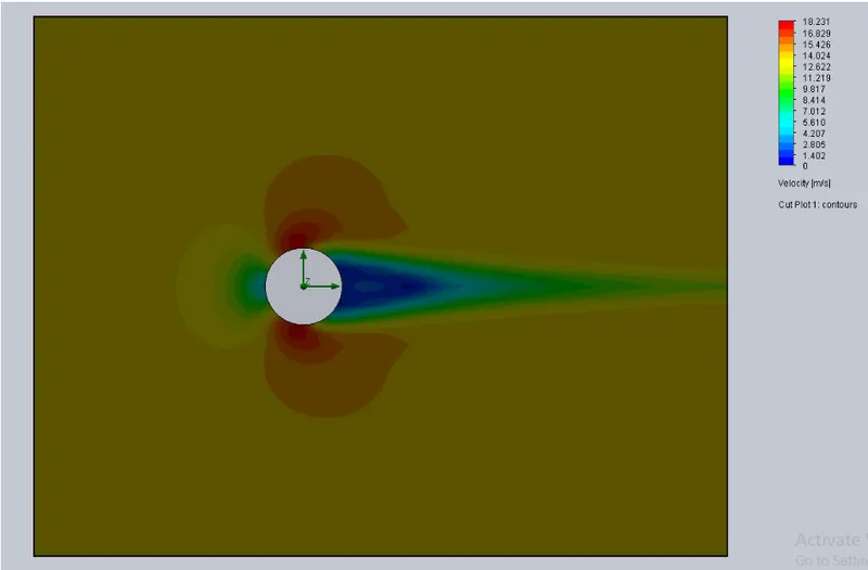
Here min=0m/s and max= 18.231m/s
PRESSURE CONTOUR
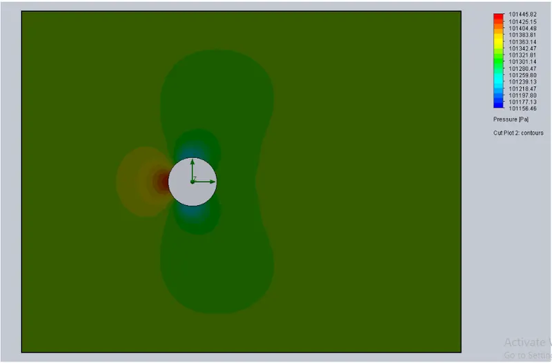
Here min=101156.46Pa and max=101445.82Pa
VELOCITY ANIMATION
PRESSURE ANIMATION
CASE 4 INLET FLOW VELOCITY=20m/s, Reynolds number increased ny 100%
VELOCITY CONTOUR
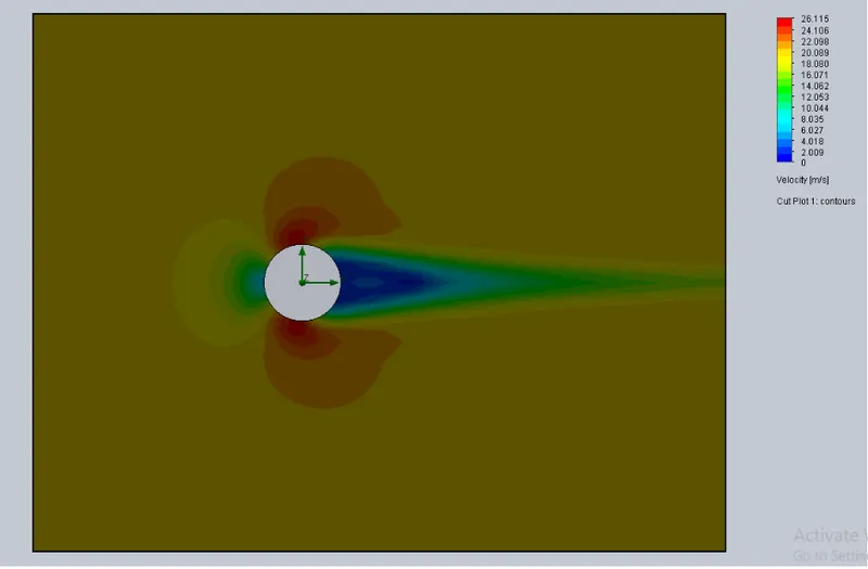
Here min=0m/s and max=26.115m/s
PRESSURE CONTOUR
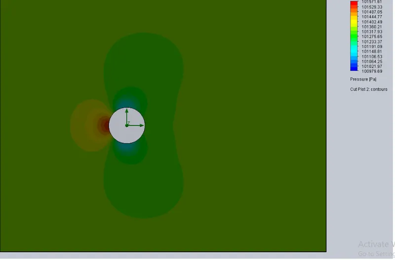
Here min=100979.69Pa and max=101571.61Pa
VELOCITY ANIMATION
PRESSURE ANIMATION
OBSERVATION TABLES:
For velocity-
| Inlet velocity | 10m/s | 12m/s | 14m/s | 20m/s |
| Min velocity | 0.497 | 0.546 | 0.656 | 0.939 |
| Max velocity | 12.676 | 15.221 | 17.772 | 25.427 |
For Pressure-
| Inlet velocity | 10m/s | 12m/s | 14m/s | 20m/s |
| Min pressure | 101276.00 | 101254.53 | 101229.07 | 101129.11 |
| Max pressure | 101379.52 | 101403.50 | 101431.86 | 101543.08 |
CONCLUSION:
1. For each reynold number the maximum velocity can be seen on the leading face of cylinder and minimum can be seen at back of cylinder
2. At the front end of the cylinder the maximum value of pressure is obtained.
3. When the reynolds number increase, velocity also increases.
4. We can say that from this simulation analysis we can analyse the maximum and minimum regions of velocity and pressure over the cylinder wih different inlet velocities and Higher the Reynolds number Higher the velocity and pressure across the geometry.