Centrifugal pump design and analysis
AIM: Perform a flow simulation on centrifugal pump and obtain relationship between pressure ratio and mass flow rate.
OBJECTIVES: Obtain a performence diagram.
Obtain relationship between pressure ratio and mass flow rate.
We should know that -
Pressure ratio= Outlet total pressure/Inlet total pressure.
THEORY:
A Centrifugal Pump is a mechanical device which is designed to move a fluid by means of the transfer of rotational energy from one or more driven rotors, called impellers. The action of impeller incereases the fluid's velocity and pressure and also directs it towards the pump outlet.
The rotational energy comes from an engine or electric motor. They are a sub class of dynamic axisymmetric work absorbing turbomachinery.
The fluid enters the pump impeller along or near to a rotating axis and is accelerated by the impeeller, flowing radially outward into a diffuser or volute chamber.
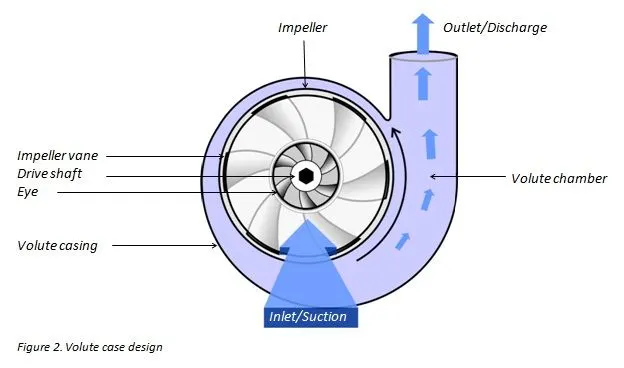
An impeller is a rotating component equipped with blades and vanes used in centrifugal pumps which allows mechanical power to be converted into pump output power.
PROCEDURE:
First we have to design a centrifugal pump so that we can have simulation analysis o it .
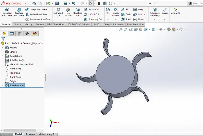
create a circle using the front plane of radius 0.02m and take another of 0.04m. using the arc tool make the blade of impeller and then by choosing the circular pattern make it count to 5 and then extrude the drawing using mid plane to a height of 0.015m.
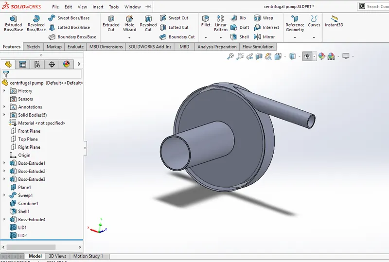
Now we have to make the outer casing for this impeller by clicking on the plane and drawing circle of radius about 0.045m and then extruding it through midplane . The most important thing to take care here is that we have to uncheck the MERGE RESULTS icon while extruding .
Then make the intake port of length about 0.07m and also make the outlet port and make sure the same thing MERGE RESULTS is being turned off.
After completing the model we have to combine it going to direct editing and selecting the parts so that whole geometry can be joined properly.
For the flow simulation we have to create an area which just touches the blade inside the geometry and that is the most important part of this challenge.
Now we can save the model and can go to the flow simulation part.
FLOW SIMULATION:
After creating lids at the both ends of inlet and outlet ports go to Wizard and select the following option-
Name of project- Centrifugal pump analysis
Flow type- Internal
Rotation- Local region averaging
Fluid - Water
For rest default options are selected.
Now a computational domain is created over the geometry.
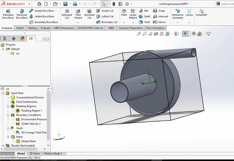
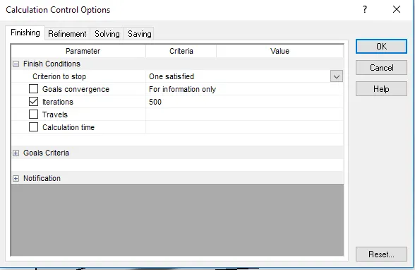
Click on iput data and fo to calculation control option and unselect all options and instead of iterations and make its value 500.
Insert rotating region as the boss extrude 4 and make the vale to 1000rad/s.
Now insert the boundary conditions - Inlet port as the enviromental pressure and outlet opening as outlet velocity as 10m/s.
Insert surface goals -Total average pressure at inlet and outlet and mass flow rate.
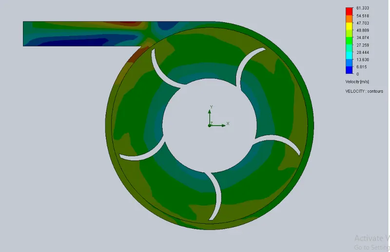
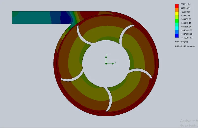
Cut plots- Top plane for velocity and pressure.
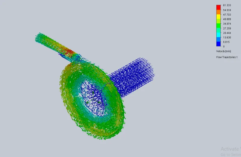
Flow trajectories- select inlet and outlet as boundaries for velocity and pressure.
First runn the BASELINE SIMULATION.
RESULTS FOR BASELINE SIMULATION:
Pressure trajectories:
Velocity trajectories:
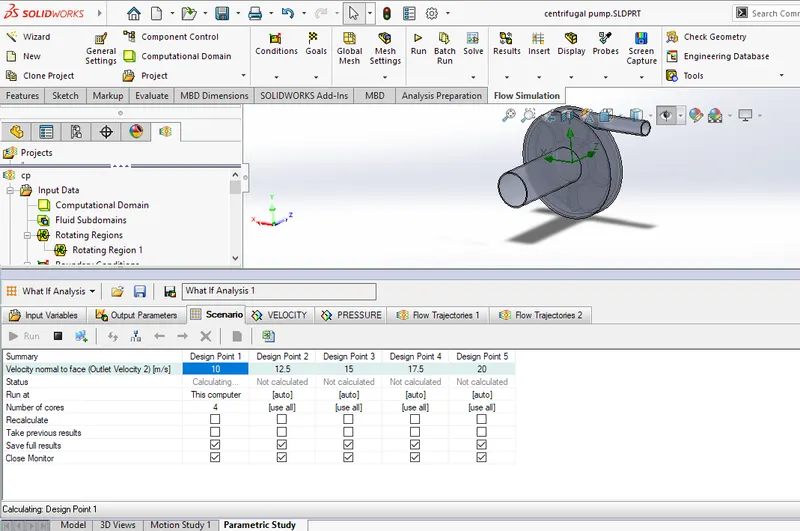
PARAMETRIC STUDY:
Iput parameter - inlet flow velocity,
Output parameter - All goals and cutplots
Scenario- Inlet flow velocity, total 5 ranging from 10m/s to 20m/s.
Click on Run.
RESULTS:
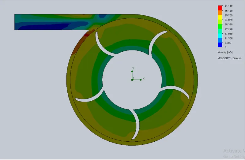
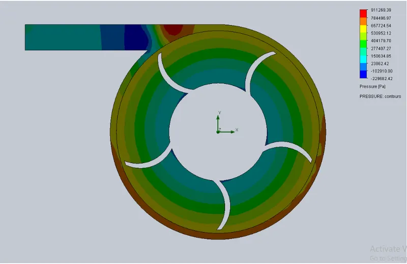
When velocity is 10m/s-
Velocity contour:-
Pressure contour:
Velocity Trajectory:
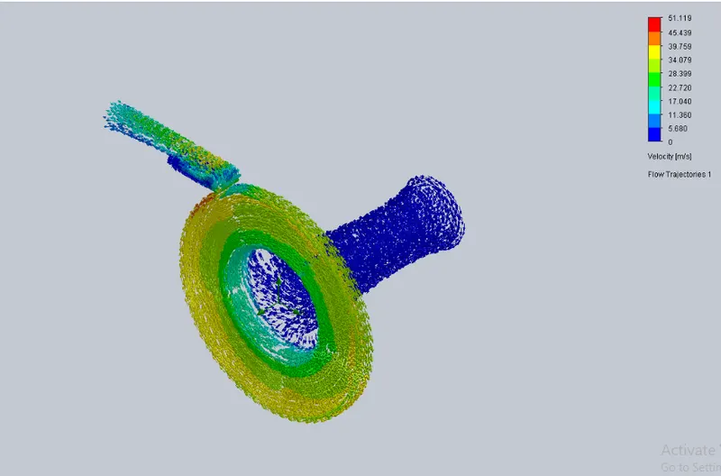
Pressure Trajectory:
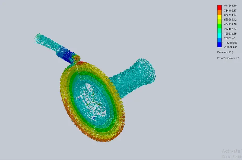
When velocity is 12.5m/s-
Velocity Contour:
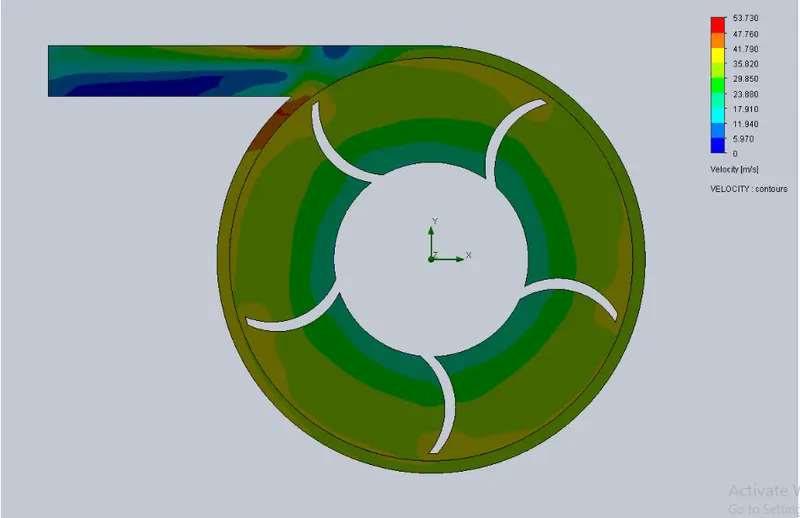
Pressure Contour:
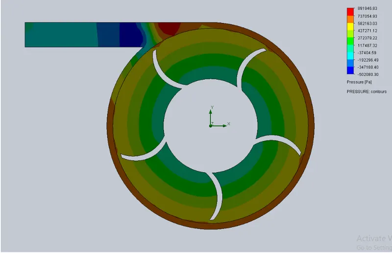
Velocity Trajectory:
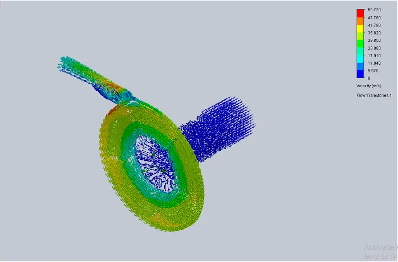
Pressure Trajectory:
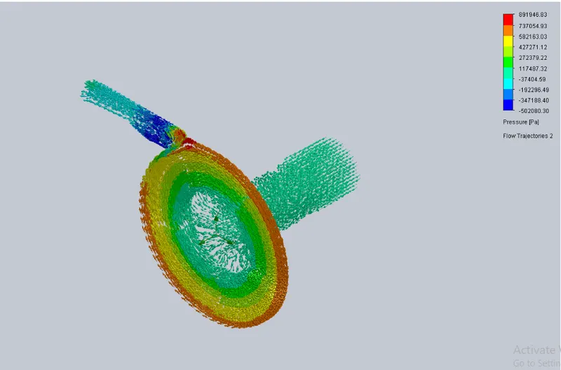
When velocity is 15m/s:
Velocity Conour:

Pressure Contour:
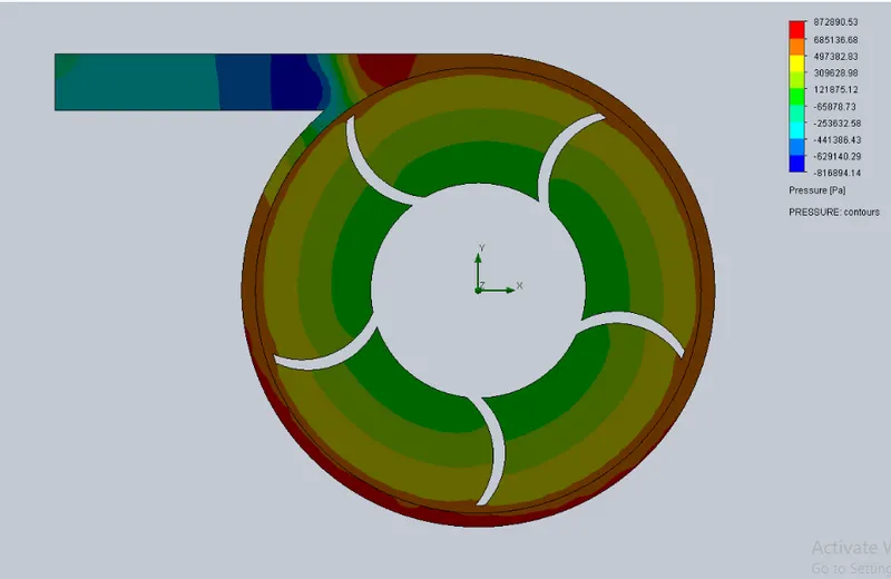
Velocity Trajectory:
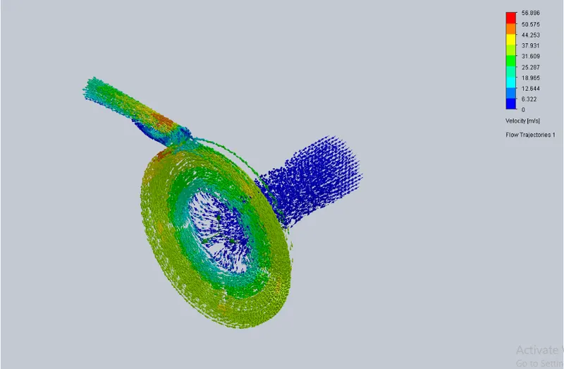
Pressure Trajectory:
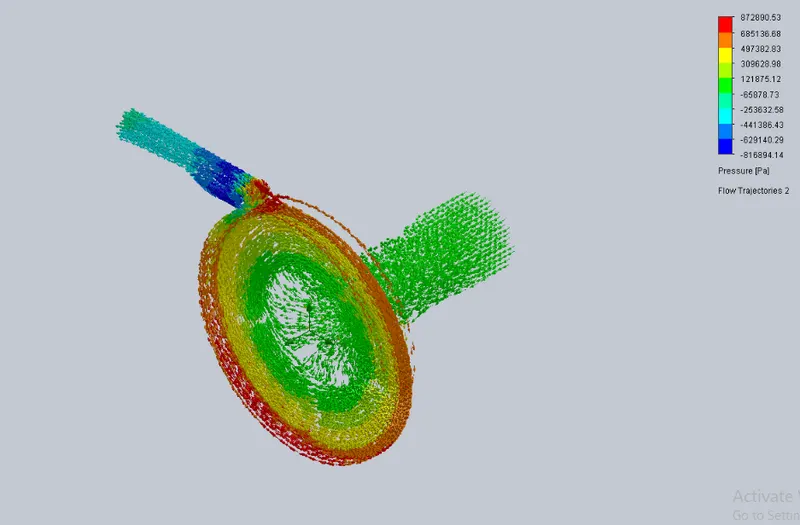
When velocity is 17.5m/s:
Velocity contour:
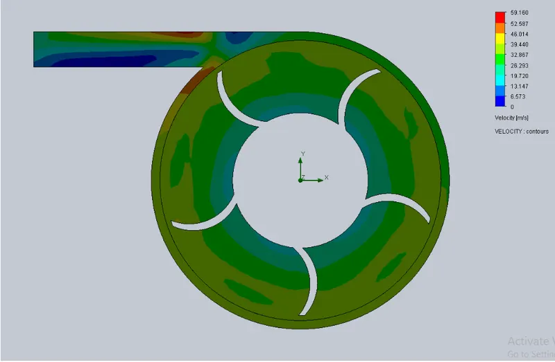
Pressure Conour:
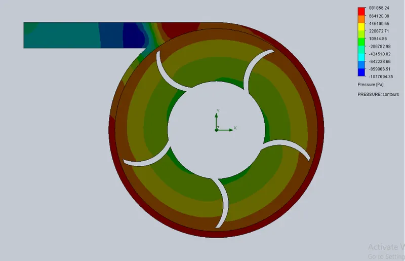
Velocity Trajectory:
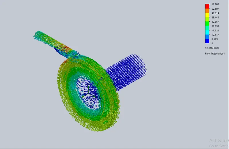
Pressure Trajectory:
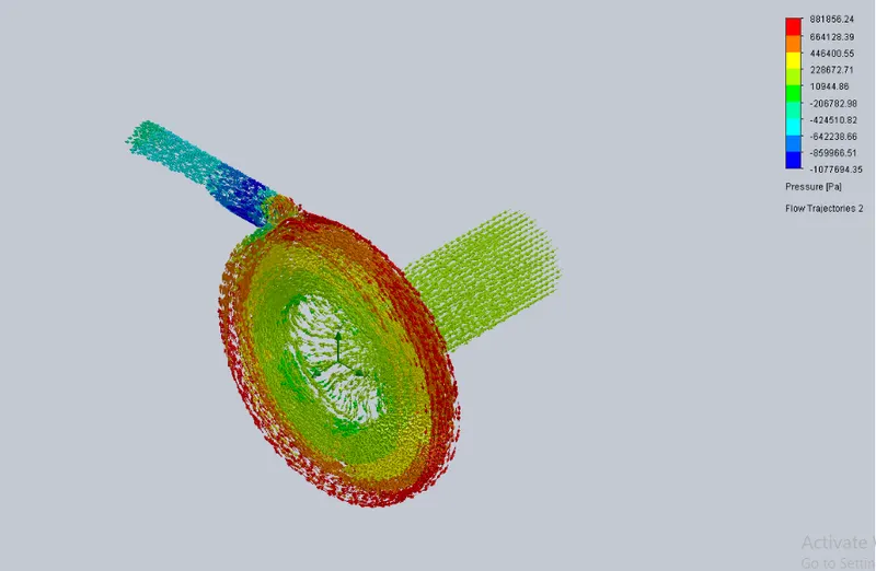
When velocity is 20m/s:
Velocity contour:
Pressure contour:
Velocity Trajectory:
Pressure Trajectory:
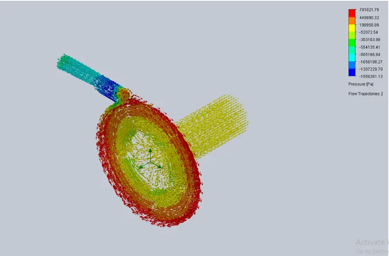
GOAL PLOT:
CONCLUSION:
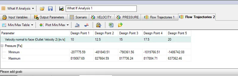
1. Increase in velocity results in an increase in mass flow rate. As mass flow rate increases, the pressure ratio also increases.
2. Negative sign indicates flow of luid at outlet port.
3. The pressure ratio will decrease with an increase in velocity at outlet.
4. Velocity increase at outlet is linear as the inlet velocity increases.
5. The higher pressure is formed at the end of the volute which is highest when the velocity increases.