Final Project: Electric Rickshaw modelling
Modelling of Electric Rickshaw using Simulink
Electric rickshaws (also known as electric tuk-tuks or e-rickshaws or toto or e-tricycles) have been becoming more popular in some cities since 2008 as an alternative to auto rickshaws and pulled rickshaws because of their low fuel cost, and less human effort compared to pulled rickshaws. They are being widely accepted as an alternative to petrol/diesel/CNG auto rickshaws. They are three-wheelers powered by an electric motor ranging from 650 to 1400 Watts. They are mostly manufactured in India and China, only a few other countries manufacture these vehicles. Battery-run rickshaws could be a low-emitter complementary transport for the low-income people, who suffer most from a lack of transport facility, if introduced in a systematic manner according to experts.
To simulate an electric rickshaw, we need to understand the topology or the block diagram of the electric vehicle at the first hand. The block diagram for an electric vehicle simulation is as follows:
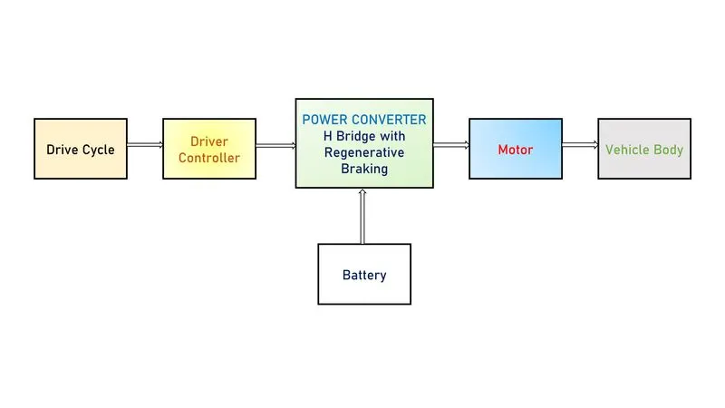
Vehicle Body: Vehicle body is simply the frame of the vehicle which includes components such as wheels, chassis, transmission system, axles etc. Simulink readily has a "Vehicle body" block under simscape library where we can feed parameters such as mass of the vehicle, Drag , Pitch etc. The actual vehicle body also includes wheels which is also available in the simscape library as "Tires(Magic Formula)". Other than these components, we can also include simple gear block to simulate the transmission system.
Motor: The motor in the electric vehicle is the machine that converts the electrical energy from the battery into mechanical energy so that we could drive the wheels. There are different motors used in the actual EVs namely induction motor, BLDC motor, Internal Permanent Magnet Synchronous Reactance Motor etc. In our simulink model, for the sake of simplicity, we use DC Motor for simulation.
Battery: Like the petrol or diesel in the IC engine vehicles, the source of fuel for the electric vehicle is the battery. A battery pack in a EV will consist of many individual cells of lower voltages stacked together in series connection to get a larger net voltage battery pack. Many of the EV manufactures like Tesla, Nissan , Audi etc use Lithium Ion batteries in their vehicles. This battery supplies a constant DC voltage and it is connected with a motor controller.
Power Converter: Power converter can be regarded as the brain or processing unit of an electric vehicle. It basically consists of power electronic devices. It is the one which enables the control of an Electric vehicle. Because, the voltage from the battery is a constant DC and if it is given directly to the motor (say BLDC), the motor would always run at constant speed and we could NOT achieve the speed control of the motor. This problem is solved by the power converter which consists of inverter or chopper configurations according to the motor used and it employs various techniques such as Vector Field control, PWM etc to control the speed of the motor.
Drive Cycle and Driver Controller: These blocks are specific to the simulation purposes as they act as the reference for the simulation of the model. The drive cycle is simply a velocity vs time plot and this is fed to a driver controller which takes in the input speed and the current output speed and compares both the speeds to get the error. This error is then rectified by doing acceleration or braking inorder to satisfy the reference drive cycle.
For our simulation, let us consider Mahindra Treo Yaari SFT EV. Mahindra Treo is a revolutionary new range of electric autos, e-rickshaw and cargo version. Powered by the advanced Lithium-ion technology, Mahindra Treo offers higher savings, superior ride quality and best in-class interior space. It is chosen for this simulation model because of its gaining popularity and also for the vehicle data which is available in the open source.
The Simulink model of the Mahindra Treo EV is as follows:
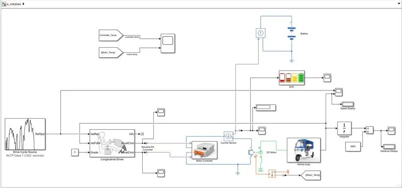
The overall structure of the model resembles with the block diagram as discussed above. The subsystems in the simulink model are:
1.) Motor Controller
2.) Vehicle Body
3.) State of Charge Subsystem (SOC)
Vehicle Body Subsystem:
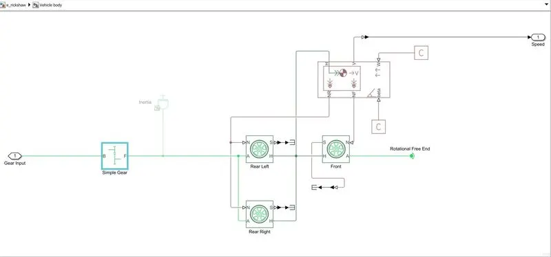
The vehicle body subsystem consists of "Vehicle body" block, "Tires(Magic Formula)" blocks and a "Simple Gear" block from the simscape library. The tires are connected to a common hub from the vehicle body and the axles are connected within the front tire and the rear tires. The normal forward force and the normal reverse force are given to the front and rear tires respectively. The wind velocity and the angle of inclination of the vehicle are given with the help of physical constants. A simple gear block here simulates the tranmission system of the vehicle in a simple way.
Data of Vehicle body from the official site:
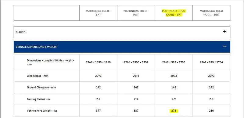
The data for frontal area and the air density is taken from one of the papers published whose link is given below:
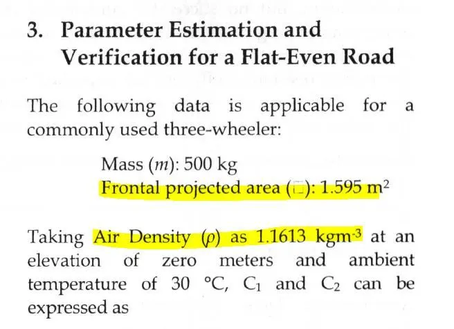
The drag co.efficient is assumed as 0.45 which is a considerable value for the three wheelers.
Now, these values are fed into the parameter blocks as follows:
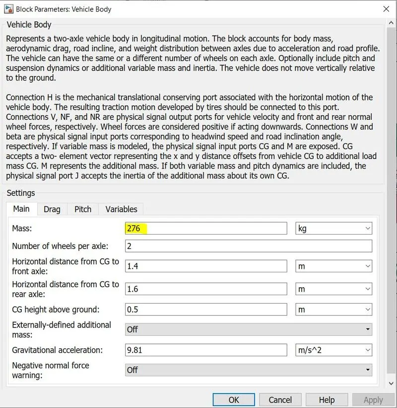
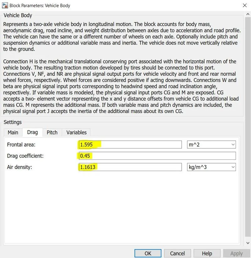
The tire radius was found as 12 inch which translates to 0.306m.
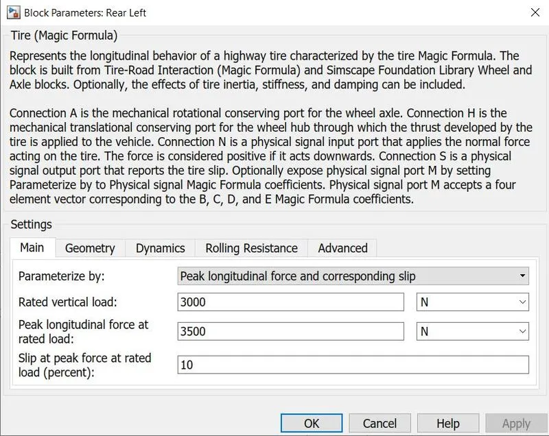
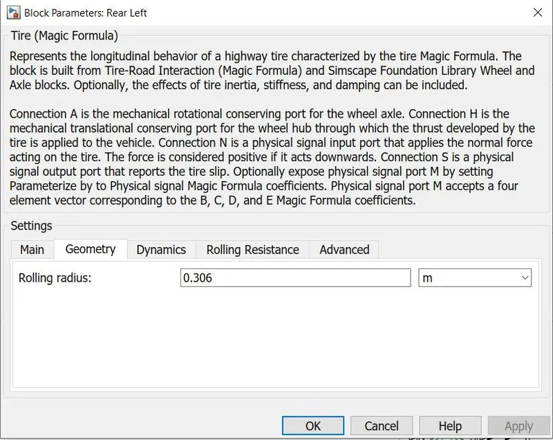
The gear ratio is assumed as 5 and the wind velocity and the vehicle inclination are given as 0 for the sake of simplicity.
Motor Controller Subsystem:
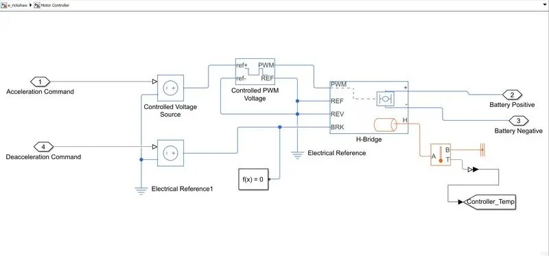
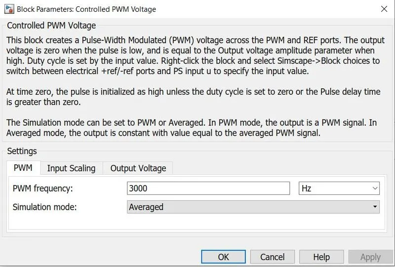
The motor controller subsystem consists of blocks such as "Controlled Voltage Source", "Controlled PWM Voltage", "H-Bridge" and a solver configuration. Here, the accleration and the deacceleration command are received from the logitudinal driver block and Pulses of variable width are produced by the "Controlled PWM voltage" block are fed into the H bridge. The H-bridge then gives a voltage to the battery corresponding to the pulse. This variable voltage across the battery inturn controls the speed of the DC motor. The temperature measurement port is also enabled to sense the temperature of the controller during the operation. The initial temperature is set to 25 degree celsius or 298.15 Kelvin
The block parameters are given below:
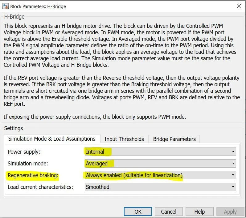
Important Note: The regenerative braking option in the H bridge block should always be enabled in order to ensure the energy feedback to battery and also to comply the vehicle inaccordance with the drive cycle.
H bridge Converter
An H-bridge is an electronic circuit that switches the polarity of a voltage applied to a load. Most DC-to-AC converters (power inverters), most AC/AC converters, the DC-to-DC push–pull converter, isolated DC-to-DC converter, most motor controllers, and many other kinds of power electronics use H bridges.
The term H-bridge is derived from the typical graphical representation of such a circuit. An H-bridge is built with four switches (solid-state or mechanical). When the switches S1 and S4 (according to the first figure) are closed (and S2 and S3 are open) a positive voltage is applied across the motor. By opening S1 and S4 switches and closing S2 and S3 switches, this voltage is reversed, allowing reverse operation of the motor.
Using the nomenclature above, the switches S1 and S2 should never be closed at the same time, as this would cause a short circuit on the input voltage source. The same applies to the switches S3 and S4. This condition is known as shoot-through.
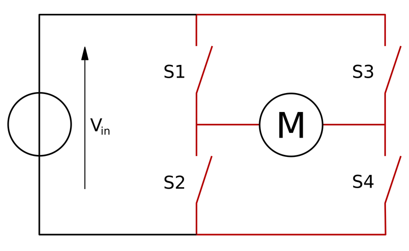
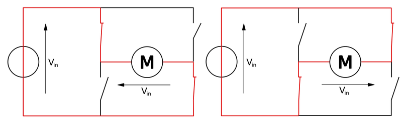
The above two diagrams shows the structure of the H-Bridge and the two basic states of an H-Bridge.
SOC Subsystem:
The SOC subsystem is employed to obtain the percentage drain in the battery of the simulated vehicle.
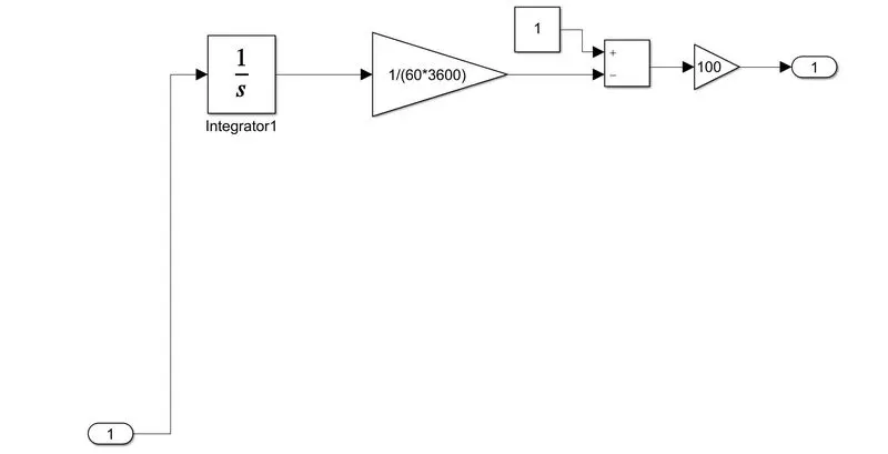
DC Motor:
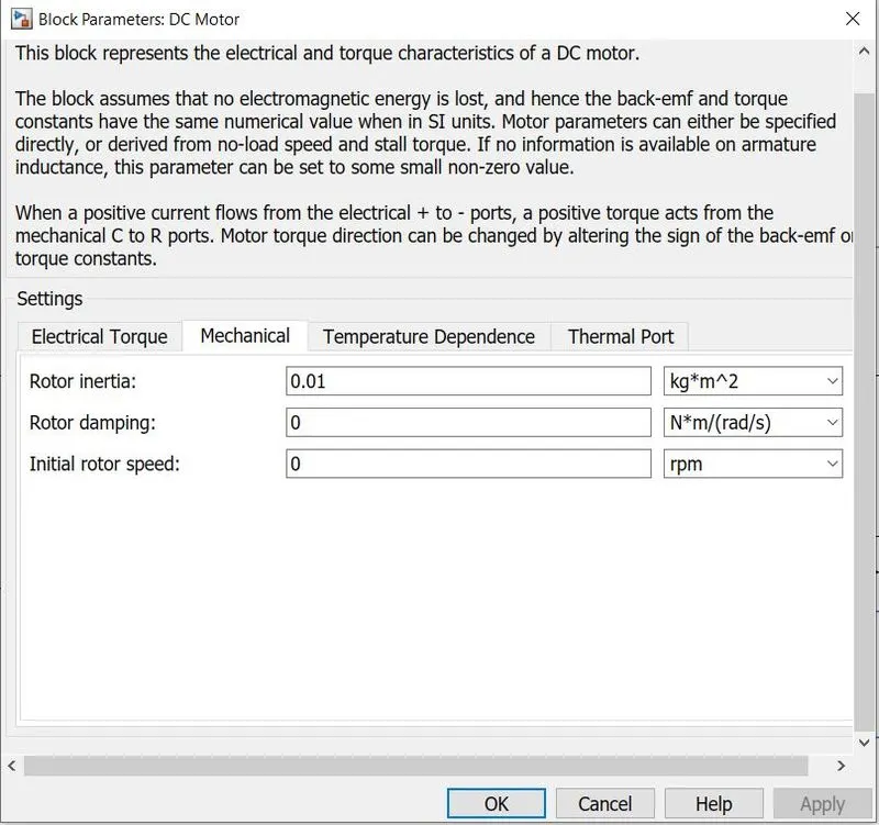
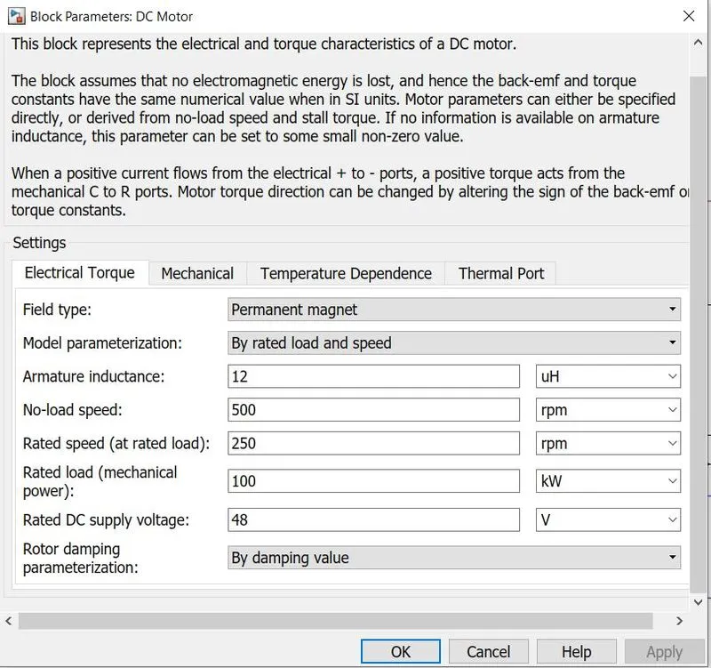
As per the requirement, (i.e Rear wheels has to be driven by PM brushed type motor) DC motor from the simscape library is used. As per the data sheet of Mahindra Treo, the peak power is around 2kW and peak torque requirement is around 22 Nm. Considering this in mind and also the temperature limitations, the parameters of the DC motor are experimented to get the optimum value. For the WLTP1 drive cycle, the optimum parameters are given below.
Note: The temperature measurement port is enabled to measure the temperature of the motor during the operation.The initial temperature is set to 25 degree celsius or 298.15 Kelvin.
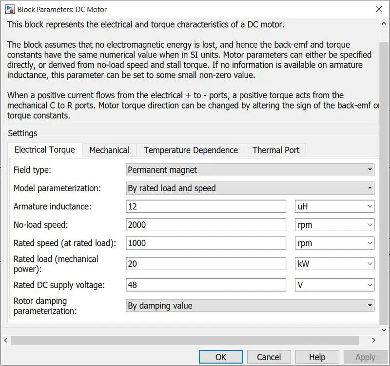
Longitudinal Driver:
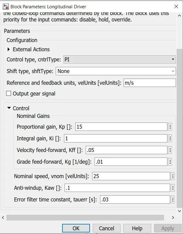
It is a parametric longitudinal speed tracking controller for generating normalized acceleration and braking commands based on reference and feedback velocities. From the simulink model, we could see that the vehicle output speed is fedback and compared with the reference speed (drive cycle) inorder to obtain the acceleration command and the deacceleration command. The block parameters are left default as given below(PI controller is used).
Drive cycle:
Drive cycle is simply a speed vs time graph. It is generally used for various vehicle testings and simulations. Let us test the model for three different drive cycles.
- WLTP Class 1
- FTP 75
- WOT
Simulation Results
1. WLTP Class 1 drive cycle
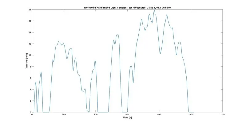
Speed:
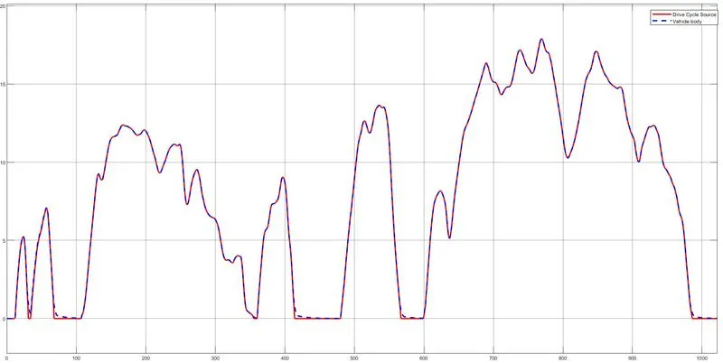
Hence we could see that the vehicle body speed exactly matches with the reference(i.e drive cycle)
Distance Travelled:
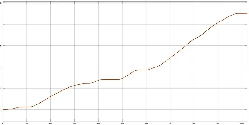
The distance travelled for this drive cycle is around 2.3 kms
SOC
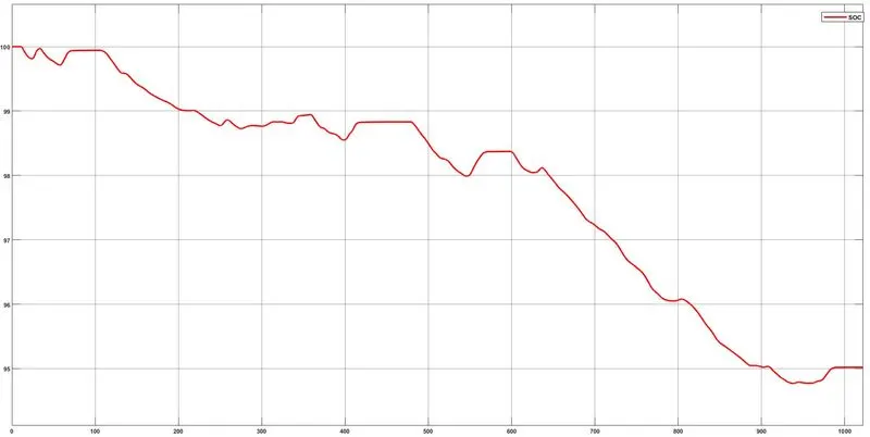
The battery is drained for about 5%. Some of the energy in the battery is recovered due to regenerative braking.
Motor and controller temperature
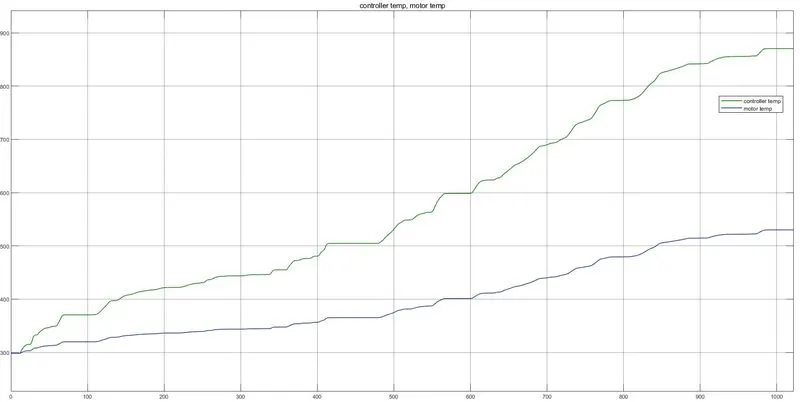
Here, the Y axis(i.e the temperature) is in kelvins. We could clearly see that the motor reaches a much higher temperature than the controller. This indicates that the thermal management is very essential.
2.)FTP75 Drive cycle:
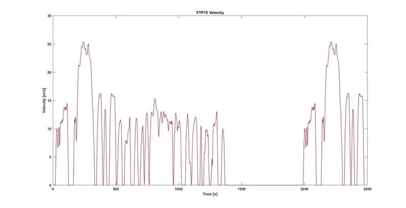
With FTP75 drive cycle and DC motor parameters same as that of WLTP class 1, the motor temperature goes to an abnormal value. Hence, the motor parameters are modified a little in order to achieve desirable operation. The modified motor parameter is given below:
Speed:
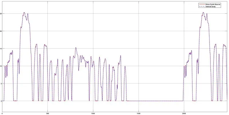
Hence the speed of the vehicle matches with the reference.
Distance Travelled:
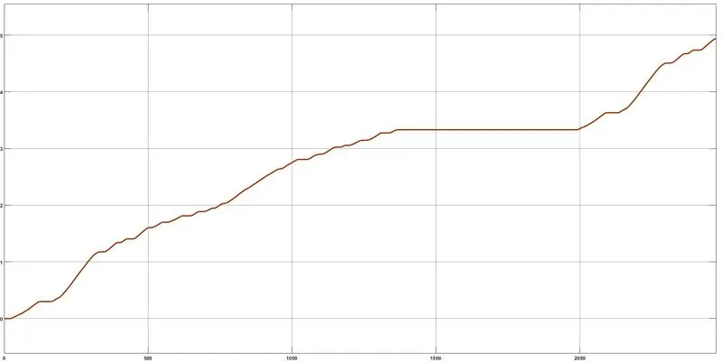
Hence, the distance travelled for this FTP75 drive cycle is around 5 Kms
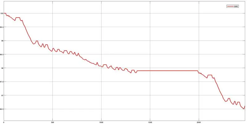
SOC
Motor and Controller Temperature
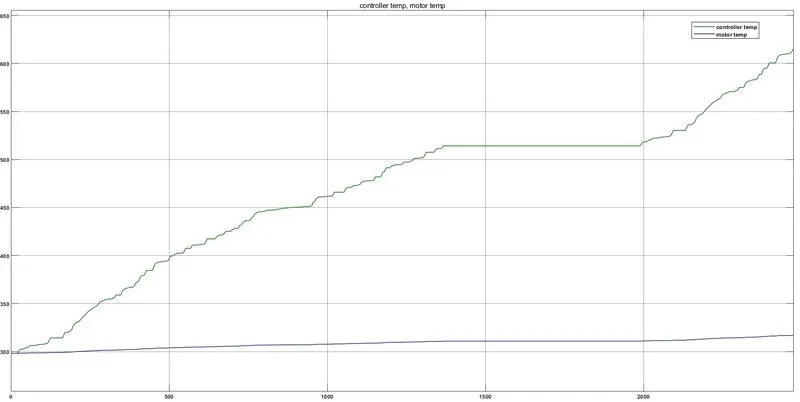
Hence, for FTP75 also the motor temperature goes to a slightly higher temperature. Therefore, Thermal management is necessary here.
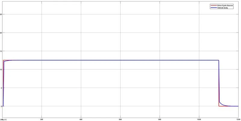
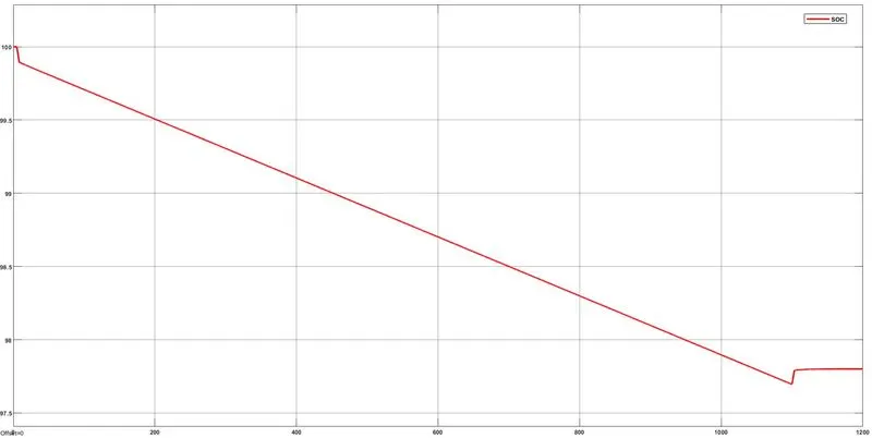
3.) WOT [45km/hr for 20 mins]
Here, the motor parameters remains the same as that of previous FTP75 drive cycle.
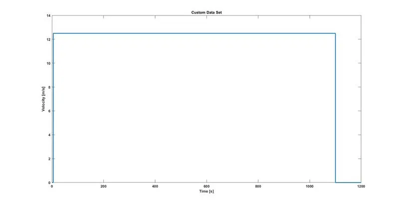
Speed:
Distance Travelled:
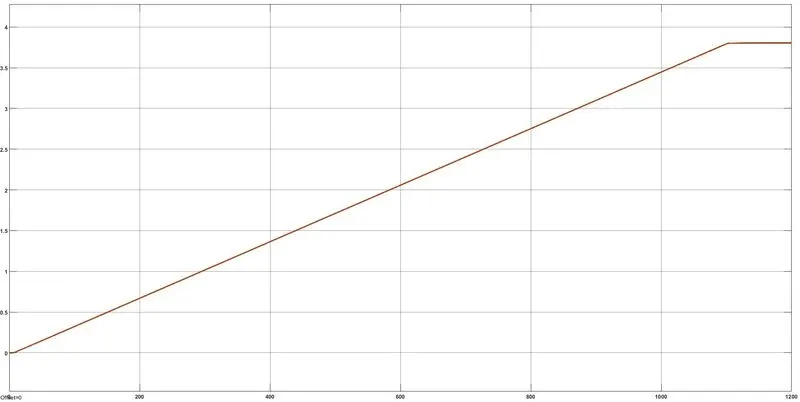
Here, the distance travelled is around is 3.8 Kms
SOC
Motor and Controller Temperature
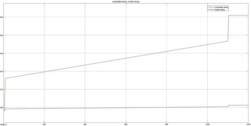
Conclusion
Thus, an electric rickshaw model is created in simulink and simulated. More accurate and practical results can be obtained by giving more accurate parameters. Also, the DC motor used in the simulation may not match with the actual motor specifications. That is the reason to get slightly higher motor temperatures than expected. In actual scenario, motor construction is robust and also employes thermal cooling system for a better efficient vehicle.