Final Project: Electric Rickshaw modelling
Create a detailed MATLAB model of an electric rickshaw (three wheel passenger vehicle)
Electric rickshaws (also known as electric tuk-tuks or e-rickshaws or toto or e-tricycles) have been becoming more popular in some cities since 2008 as an alternative to auto rickshaws and pulled rickshaws because of their low fuel cost, and less human effort compared to pulled rickshaws. They are being widely accepted as an alternative to petrol/diesel/CNG auto rickshaws. They are three-wheelers powered by an electric motor ranging from 650 to 1400 Watts. They are mostly manufactured in India and China, only a few other countries manufacture these vehicles.Battery-run rickshaws could be a low-emitter complementary transport for the low-income people, who suffer most from a lack of transport facility, if introduced in a systematic manner according to experts.
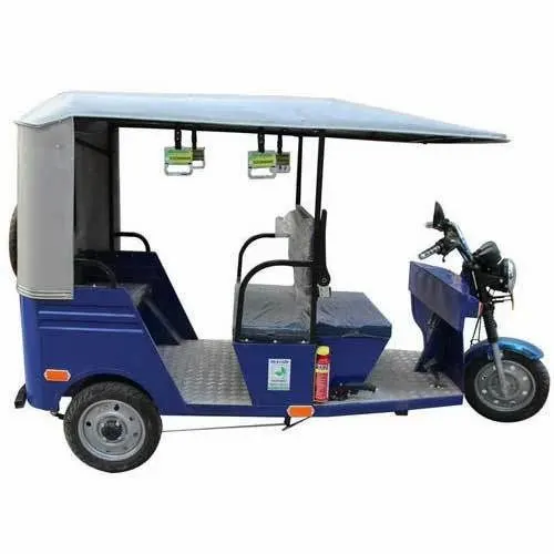
These rickshaws have a M.S(Mild Steel) tubular Chassis, consisting of three wheels with a differential mechanism at the rear wheels. The motor is brushless DC motor manufactured mostly in India and China. The electrical system used in Indian version is 48V and Bangladesh is 60V. The body design from most popular Chinese version is of very thin iron or aluminum sheets. Vehicles made in fiber are also popular because of their strength and durability, resulting in low maintenance, especially in India. Body design is varied from load carriers, passenger vehicles with no roof, to full body with windshield for drivers comfort. It consist of a controller unit.They are sold on the basis of voltage supplied and current output, also the number of mosfet (metal oxide field effect transistors) used. The battery used is mostly lead acid battery with life of 6–12 months. Deep cycle batteries designed for electric vehicles are rarely used. Weight of the electric car has also been a recurring design difficulty in them.
AIM:
In this project, we will create a MATLAB model of the ELECTRIC RICKSHAW by utilising a PM brushed type DC motor and an appropriate Lithium-Ion battery. Before that, we'll learn about Electric RICKSHAW, how it works, and the advantages of EV RICKSHAW. Then, using appropriate blocks from the powertrain block set, we create a genuine EV RICKSHAW model in SIMULINK.My major goal is to see "how my RICKSHAW performs for any three standard driving cycles displaying energy consumption, motor and controller temperature rise for vehicle cover around 100 km at constant speed driving 45 kmph."
MAIN SYSTEM:
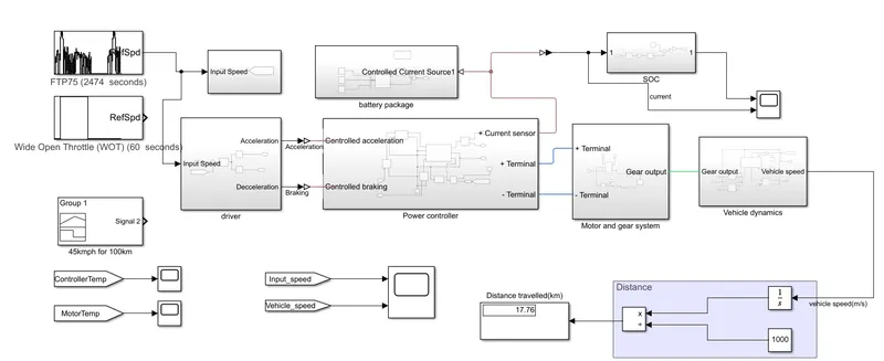
This is the main system of the electric autorickshaw.In here we can see there are some subsystems are there we can gothrough all the subsytem. So, first, we'll go through each subsystem and examine what components are included, along with a detailed explanation of how each component works.
In here we can first see about the driver subsystem
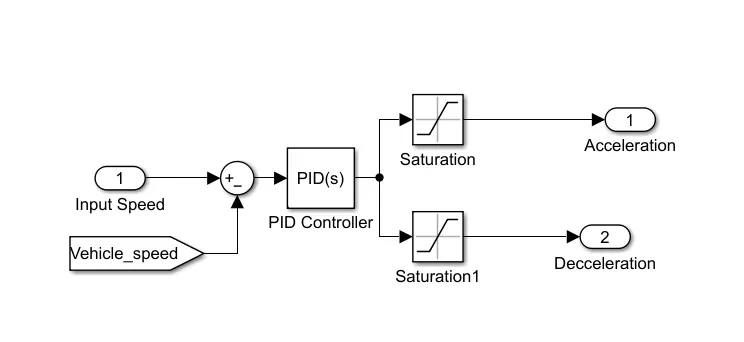
In here we are giving the input speed and vehicle speed to the PID controller it attached to the acceleration and decceleration.A PID controller is an instrument used in industrial control applications to regulate temperature, flow, pressure, speed and other process variables.PID control uses closed-loop control feedback to keep the actual output from a process as close to the target or setpoint output as possible.
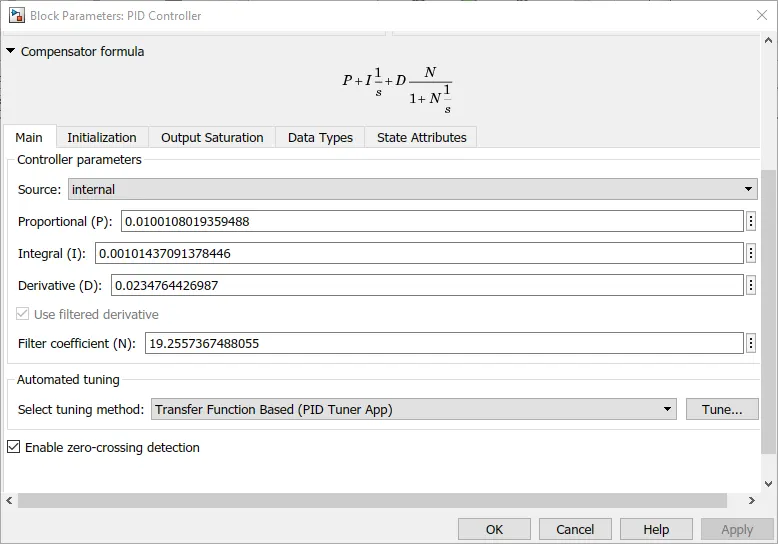
This is the PID controller block parameter shows here these are the value which we are given
And we can see the controller subsystem
Power controller subsytem
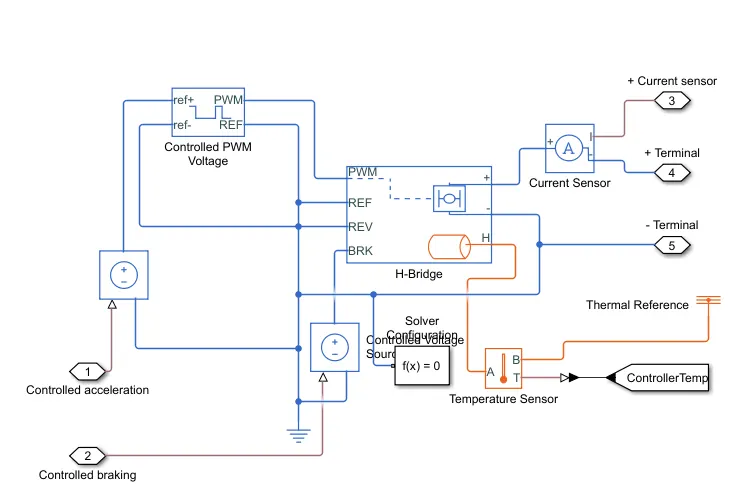
This is the controller susystem in here there are controlled PWM voltage and hbridge are there
Controlled PWM Voltage
Many industrial applications use pulse width modulation (PWM) signals because such signals are robust in the presence of noise. When using Simulink Control Design software, subsystems that contain PWM signals do not linearize well due to discontinuities in the signal.
This block generates a PWM voltage across the PWM and REF ports. When the pulse is low, the output voltage is zero, and when it is high, it equals the Output voltage amplitude parameter. The duty cycle is determined by the input value.
H-bridge block
The H-Bridge block represents an H-bridge motor driver. The block has the following two Simulation mode options: PWM — The H-Bridge block output is a controlled voltage that depends on the input signal at the PWM port.
An H-bridge motor drive is represented by this block. The Controlled PWM Voltage block can drive the block in PWM or Averaged mode. If the PWM port voltage is greater than the Enable threshold voltage, the motor is operated in PWM mode. In Averaged mode, the ratio of the on-time to the PWM period is defined by the PWM port voltage divided by the PWM signal amplitude parameter.The block delivers an average voltage to the load that produces the right average load current using this ratio and assumptions about the load. The Simulation mode parameter value for the Controlled PWM Voltage and H-Bridge blocks must be the same. In layman's terms, it's a set of four switches.
for this we selected the thermal port
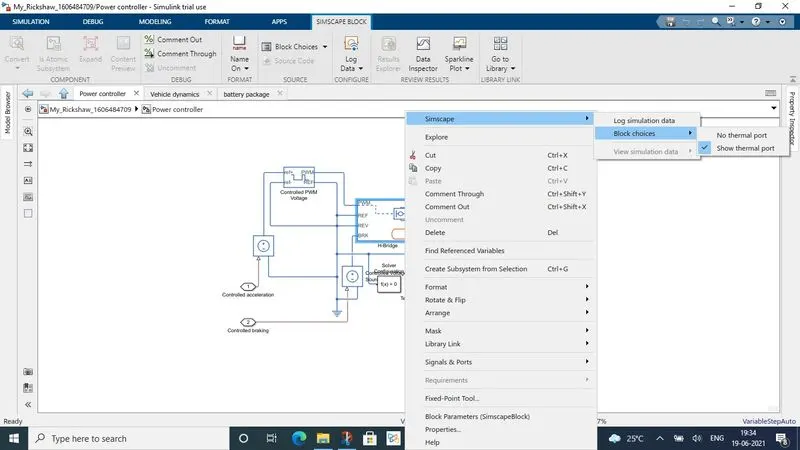
Thermal Port
The block has an optional thermal port, hidden by default. To expose the thermal port, right-click the block in your model, and then from the context menu select Simscape > Block choices > Show thermal port. This action displays the thermal port H on the block icon, and adds the Temperature Dependence and Thermal Port parameters. These parameters are described further on this reference page.
When the thermal port is visible:
-
The heat generated by the bridge on-resistance and freewheeling diodes is added to the thermal port. The thermal port has an associated thermal mass and initial temperature that you can set from the Thermal Port parameters.
-
The bridge on-resistance and freewheeling diode resistance become functions of temperature. You can define the values for these resistances and the second measurement temperature from the Temperature Dependence parameters. Resistance is assumed to vary linearly between the two measurement temperatures. Extrapolation is used for temperatures outside of this range, except for when simulating in averaged mode with discontinuous load current characteristics.
Solver Configuration
The Solver Configuration block specifies the solver parameters that your model needs before you can begin simulation. Each topologically distinct Simscape block diagram requires exactly one Solver Configuration block to be connected to it.
Current sensor
When current flows through a conductor, it creates a proportional magnetic field around the conductor. ... The sensor then outputs a certain voltage or current that a meter connected to the sensor can read and translate into the amount of current flowing through the conductor.
Temperature sensor
The Temperature Sensor block represents an ideal temperature sensor, that is, a device that determines the temperature differential measured between two points without drawing any heat. Connections A and B are thermal conserving ports that connect to the two points where temperature is being monitored
These are the thing inside the controller subsytem sowe can gothrough othe subsystems
Motor and Gear subsystem
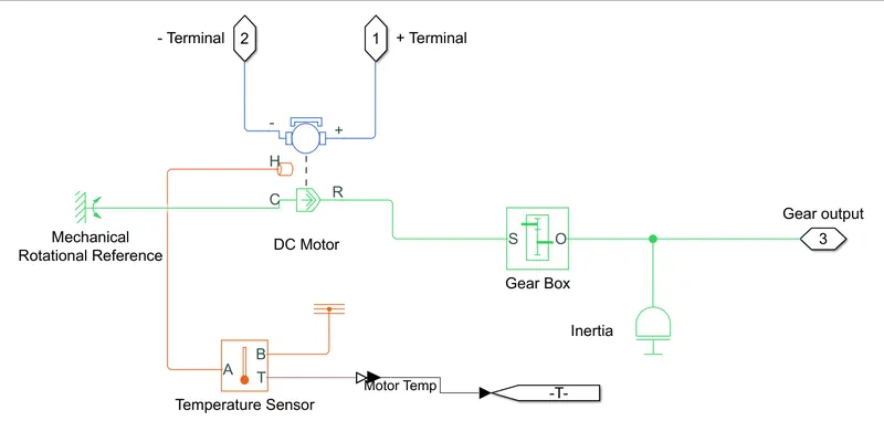
Dc Motor
The DC Motor block represents the electrical and torque characteristics of a DC motor using the following equivalent circuit model: You specify the equivalent circuit parameters for this model when you set the Model parameterization parameter to By equivalent circuit parameter.
Because the block assumes no electromagnetic energy is lost, the back-emf and torque constants have the same numerical value when expressed in SI units. Motor specifications can be supplied explicitly or calculated from no-load speed and stall torque. If no information on armature inductance is available, this parameter can be set to a tiny non-zero value.
in the dc motor in here we selected the thhermal port here too.
Use the thermal ports to simulate the effects of copper resistance losses that convert electrical power to heat.Use the thermal ports to simulate the effects of copper resistance losses that convert electrical power to heat.
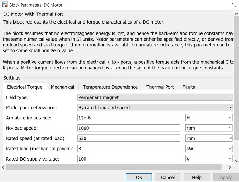
A positive torque acts from the mechanical C to R ports when a positive current flows from the electrical + to - ports. The sign of the back-emf or torque constants can be adjusted to vary the direction of the motor torque.It receives the input command from the motor controller and sends it to the transmission system. And when the car brakes, it acts as a generator, charging the battery at that time owing to regenrative braking.
We attatch the motor to the gear box
Gear box
The purpose of a gearbox is to increase or reduce speed. As a result, torque output will be the inverse of the speed function. If the enclosed drive is a speed reducer (speed output is less than speed input), the torque output will increase; if the drive increases speed, the torque output will decrease.
Temperature sensor
It is used to sense the tempeatre of the motor when the rickshaw runs.Use the thermal ports to simulate the effects of copper resistance losses that convert electrical power to heat.Use the thermal ports to simulate the effects of copper resistance losses that convert electrical power to heat and then the sensor sense the value of heat produced there.
Vehicle dynamics subsystem
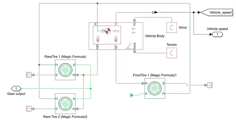
This is the vehicle dynamics block in here there a three wheels are there and vehicle body .In vehicle body we attach the wind and terrain whic we applying to the body
The above subsystem is the base of the model as, it contains:
Tires: We're designing a four-wheeled EV, therefore we'll need four of these tyres, with H representing the hub, S representing tyre slip, N representing normal force, and A representing axle connection.
Vehicle Body: The Vehicle Body block represents a two-axle vehicle body in longitudinal motion. The vehicle can have the same or a different number of wheels on each axle. ... The block accounts for body mass, aerodynamic drag, road incline, and weight distribution between axles due to acceleration and road profile.
Battery package subsystem
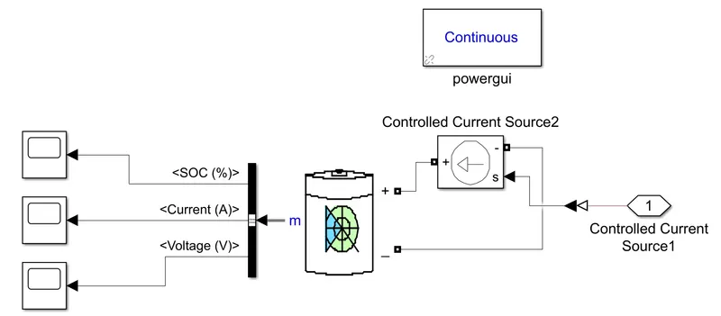
Battery :
The battery is required to power the controller and motor. The controller uses the battery power according to produce the input given by the motor to obtain maximum speed. The battery is also used to power every electrical component in the vehicle.
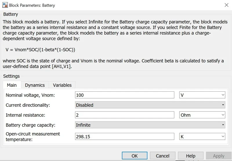
The Battery block implements a generic dynamic model that represents most popular types of rechargeable batteries.
Controlled Current Source :
The Controlled Current Source block converts the Simulink input signal into an equivalent current source. The generated current is driven by the input signal of the block. The positive current direction is as shown by the arrow in the block icon.
We can initialize the Controlled Current Source block with a specific AC or DC current. If we want to start the simulation in steady state, the block input must be connected to a signal starting as a sinusoidal or DC waveform corresponding to the initial values.
Double click controlled current source and from drop down menu of measurement select current.
Signal output will connect with scope by adding current signal to it.
(+) terminal will connect with battery (-) terminal.
Signal builder
To display, create, and edit interchangeable groups of signal sources and quickly switch the groups into and out of a model, use the Signal Builder block. You can define any piecewise linear signal shape (waveform).
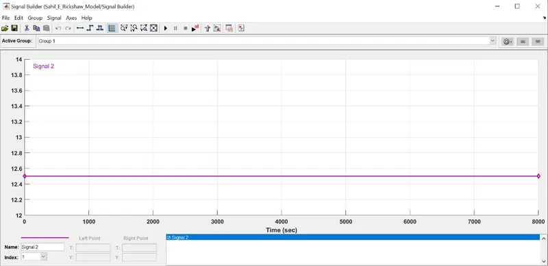
for upto 100km constant speed driving 45kmph so we given the signal builder the constant value 12.5
FTP 75
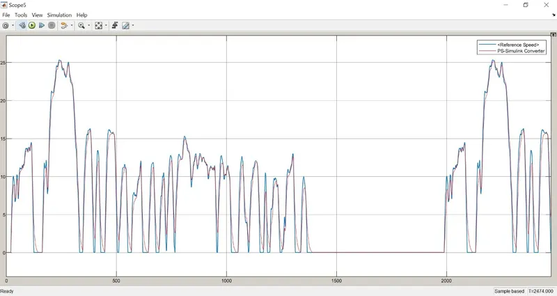
The FTP-75 drive cycle data. ... The support package has drive cycles that include the gear shift schedules
Generates a standard or user-specified longitudinal drive cycle. The block output is the vehicle longitudinal speed. You can import drive cycles from :
Predefined sources
Workspace variables, including arrays and time series objects
mat, xls, xlsx, or txt files
Use the fault tracking parameters to identify drive cycle faults within specified speed and time tolerances.
WOT (WIDE OPEN THROTTLE)
In an internal combustion engine, this state entails the maximum intake of air and fuel that occurs when the throttle plates inside the carburetor or throttle body are "wide open" (fully opened up), providing the least resistance to the incoming air.
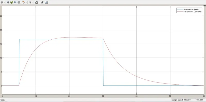
OUTPUT PLOTS
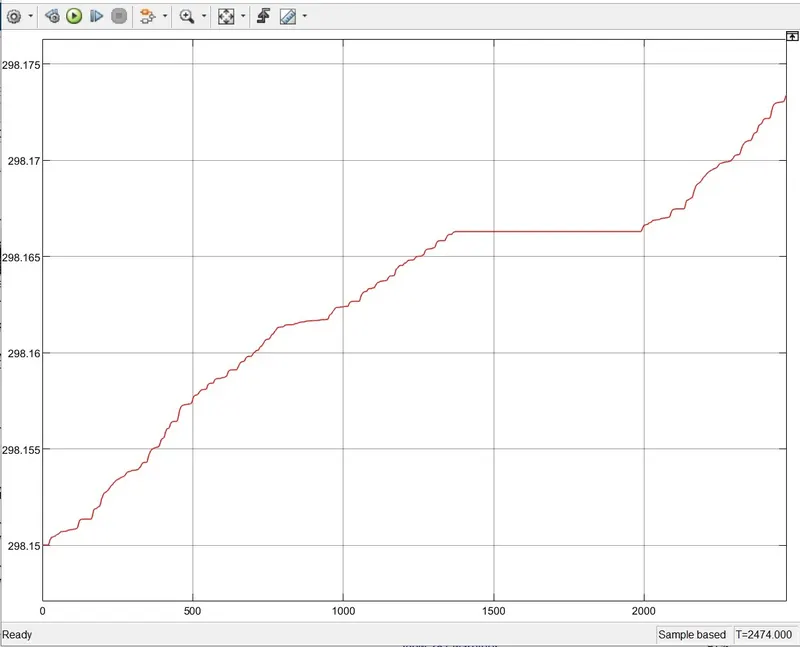
This the firsyt controll signal .It is the control signal for the input signal in this the signals are varying and increasing up to 298.16 and 298.17 inbetween at a time 298.165 it is going steadily in this the wave form is fluctuating and increasing the value
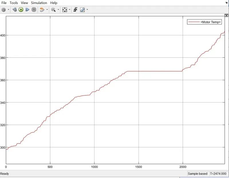
It is the motor temperature waveform in here; it begins at 300 and gradually increases to 1400; it then continues to rise as the values of the waveform fluctuate.
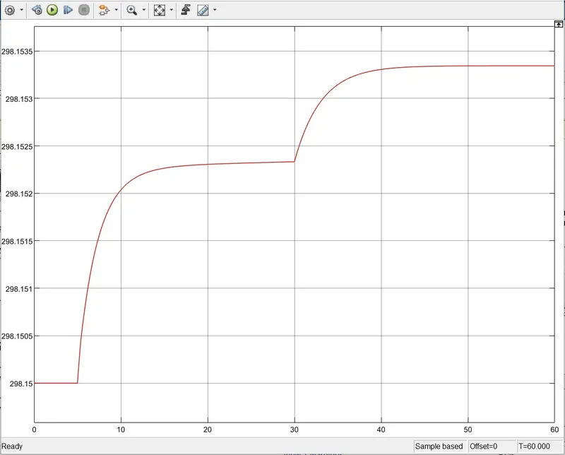
This is the second controll signal.This is the controller output, and we can see that it starts at 298.15, then climbs steadily, then rises again, as seen by the wave shapes.
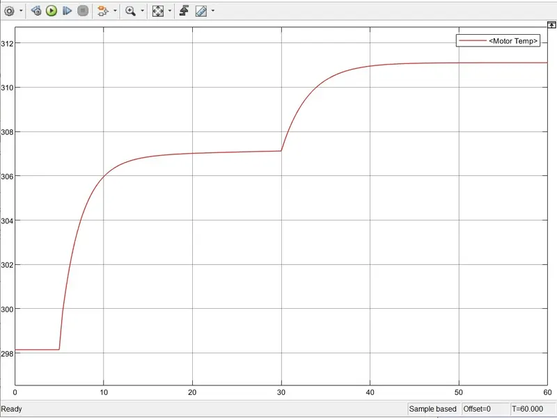
In this case, it is the temperature of the motor; after 5 seconds, it climbs to 307 and continues to grow steadily, and after 30 seconds, it rises again, as seen in the graph.
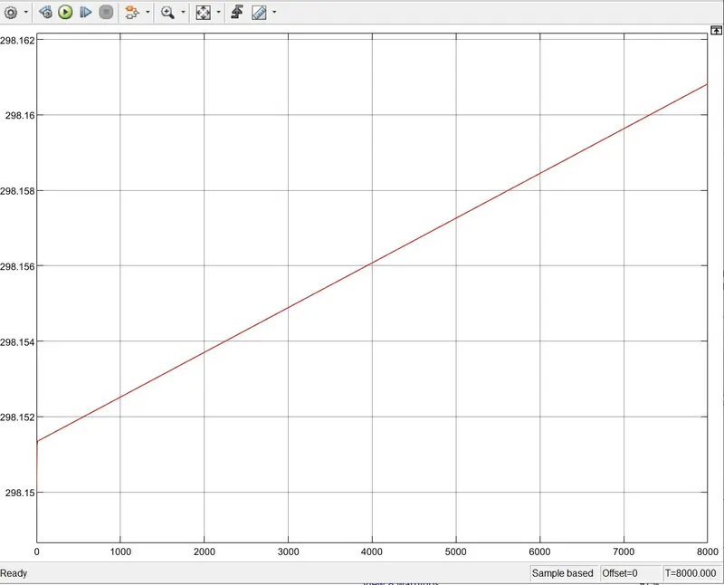
This is the third controll signal in here; it begins at 298.15 and continues to rise until it reaches time 8000, as shown in the graph.
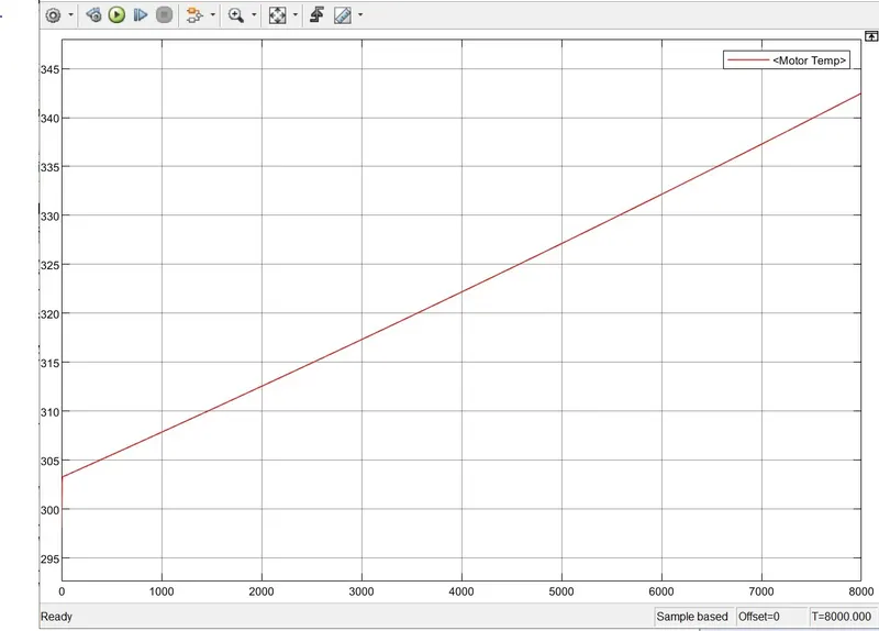
In this graph, we can observe the output graph of the motor temperature. We can see that if it starts slowly, the temperature rises and continues to rise till the time 8000.
Conclusion:
In this case, I compromised with the temperature of the motor and controller in order to reach vehicle speeds that are close to reference speeds. Because I did not include a cooling system in the model. The motor temperature is less than 100 degrees Celsius in the real-time application.The temperature of the motor, battery, and controller is managed by air cooling in the real-time application.
As a result, the temperature of these components is not raised to this amount.
As a result, I developed a MATLAB model of an Electric Rickshaw (three-wheel passenger vehicle) utilising a Li-ion battery and a PM Brushed DC motor.
For all three Reference Drive cycles, the fluctuations in temperature of the motor and controller, SoC percent, and energy spent by the vehicle were determined (i.e.; FTP75, WOT, Manually prepared).
In the future, this battery-powered Rickshaw will be the most popular means of transportation.