Final Project: Electric Rickshaw modelling
Aim: To create a detailed MATLAB model of an electric rickshaw (three wheel passenger vehicle).
Objective:
- To model the vehicle as rear wheels are driven by PM brushed type motor.
- To assume efficiency points of motor controller and motor.
- To make an excel sheet of all input and assumed data.
Introduction:
Small 3-wheeled vehicles with an electric motor and battery ranging in power from 650 to 1400 Watts are known as electric rickshaws. They are more convenient to use than pulled rickshaws while using less fuel than auto rickshaws. These rickshaws have a three-wheeled, mild steel tube frame with a differential system at the back wheels. A brushless DC motor powers the device. Bangladesh uses a 60V electrical system, whereas India uses a 48V system. The most widely used Chinese version's body is made of very thin iron or aluminum sheets. Fiberglass bodies are also well-liked because of their strength, longevity, and low maintenance requirements. From cargo carriers to passenger cars without roofs to full bodies with windshields for the convenience of the driver, body designs vary.
There is a controller unit included. They are priced according to the amount of voltage and current they produce as well as the quantity of mosfets (metal oxide field effect transistors) they include. The lead acid batteries in the car normally have a lifetime of 6 to 12 months. Rarely are deep cycle batteries made for electric cars employed. The weight of the electric vehicle has also consistently presented design challenges.
Block Diagram:
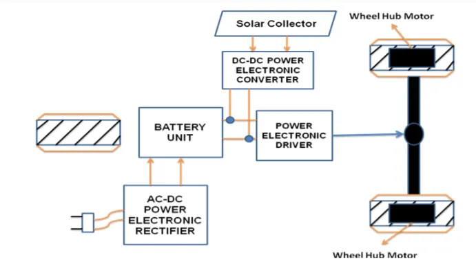
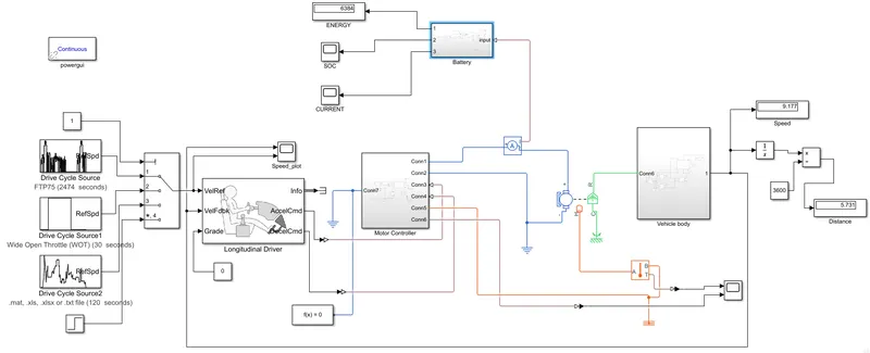
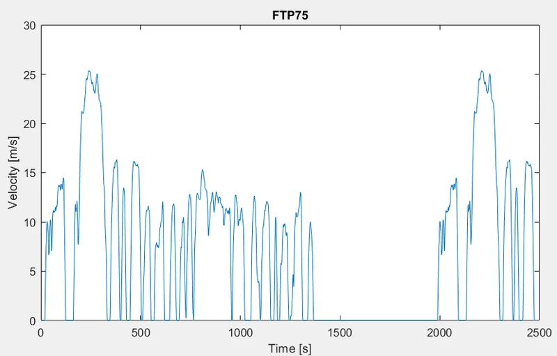
The battery, drive cycle, controller, DC motor, vehicle body, and transmission system are the primary building components of the planned Electric Rickshaw. Driving cycles are used to create the planned vehicle and to determine how it will respond to the drive cycle. These drive cycles include FTP75, WOT, and Excel (Manually Prepared in Excel sheet). The primary goals are to measure the driver's speed, estimate the motor and controller's temperature, calculate the vehicle's state of charge (SOC), and measure the distance traveled. Distance is estimated using speed and time parameters for each of the three Drive cycles, and there is a SOC block that will estimate the level of charge of a battery.
System Configuration:
System Model-
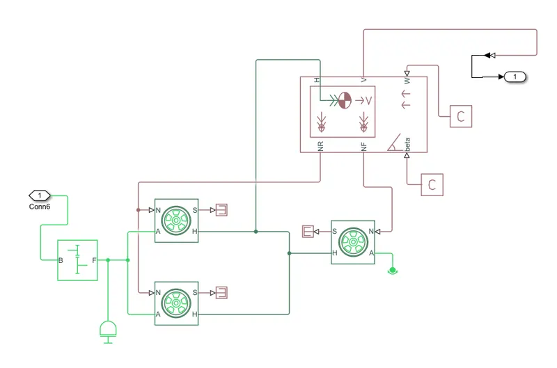
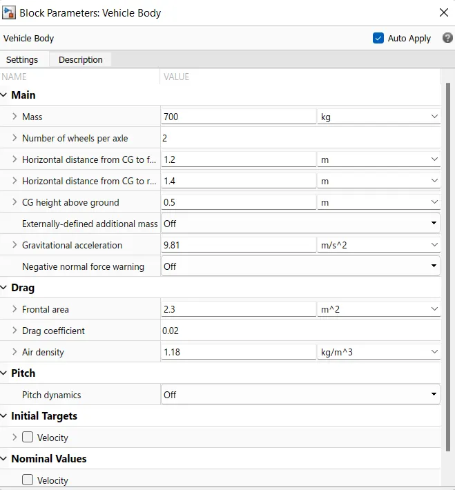
Vehicle Body-
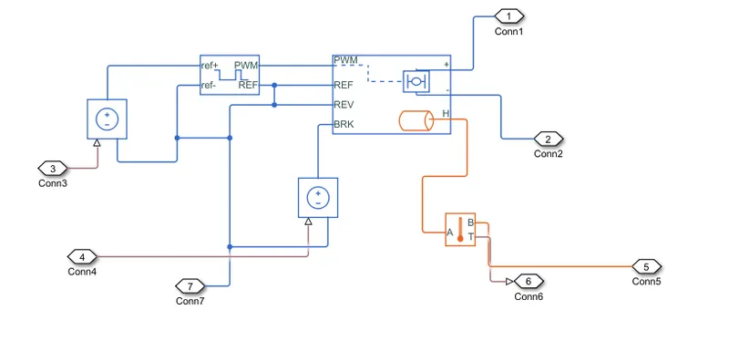
Motor Controller-
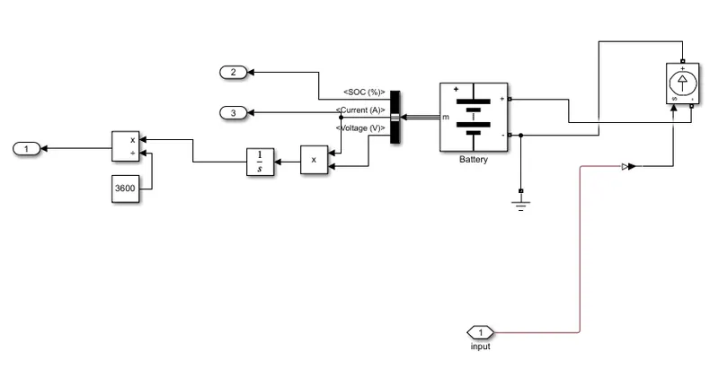
Battery-
System Parameters:
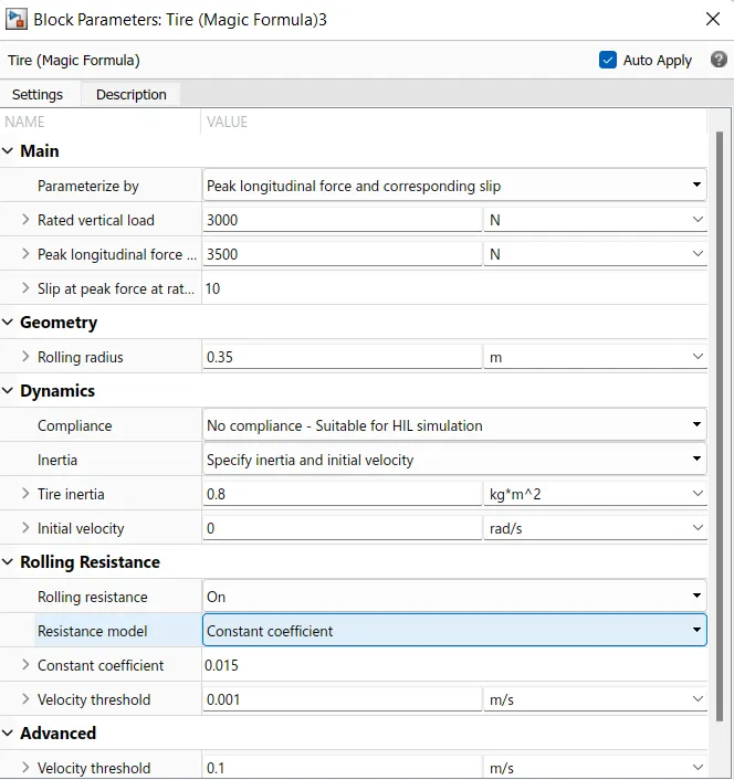
Tires-
Represents the longitudinal behavior of a highway tire characterized by the tire Magic Formula. The block is built from Tire-Road Interaction (Magic Formula) and Simscape Foundation Library Wheel and Axle blocks. Optionally, the effects of tire inertia, stiffness, and damping can be included.
Vehicle body-
Represents a two-axle vehicle body in longitudinal motion. The block accounts for body mass, aerodynamic drag, road incline, and weight distribution between axles due to acceleration and road profile. The vehicle can have the same or a different number of wheels on each axle. Optionally include pitch and suspension dynamics or additional variable mass and inertia. The vehicle does not move vertically relative to the ground.
Connection H is the mechanical translational conserving port associated with the horizontal motion of the vehicle body. Connections V, NF, and NR are physical signal output ports for vehicle velocity and front and rear normal wheel forces, respectively. Connections W and beta are physical signal input ports corresponding to headwind speed and road inclination angle, respectively. M represents the additional mass. If both variable mass and pitch dynamics are included, the physical signal port J accepts the inertia of the additional mass about its own CG.
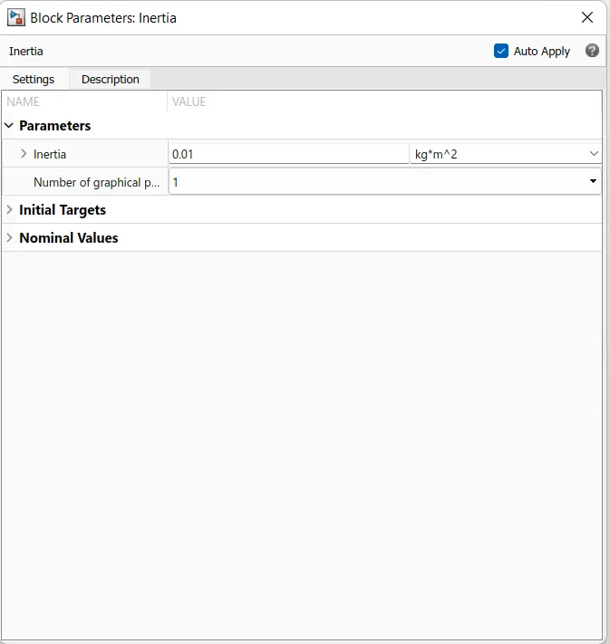
Inertia:
The block represents an ideal mechanical rotational inertia. It has one mechanical rotational conserving port. The block positive direction is from its port to the reference point. This means that the inertia torque is positive if the inertia is accelerated in the positive direction.
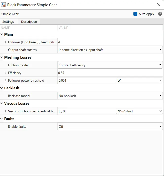
Simple Gear box:
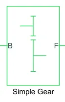
Represents a fixed-ratio gear or gear box. Base and follower connections B and F are mechanical rotational conserving ports. Use the Output shaft rotates parameter to specify how the base and follower rotation directions relate to one another. By choosing Simscape block options from the context menu when you right-click on the block to choose between the two options, you may optionally add thermal effects and reveal thermal preserving port H. The input and output shafts both revolve in the same direction. The follower is attached to the rear wheel axle, and the base is connected to the motor shaft.
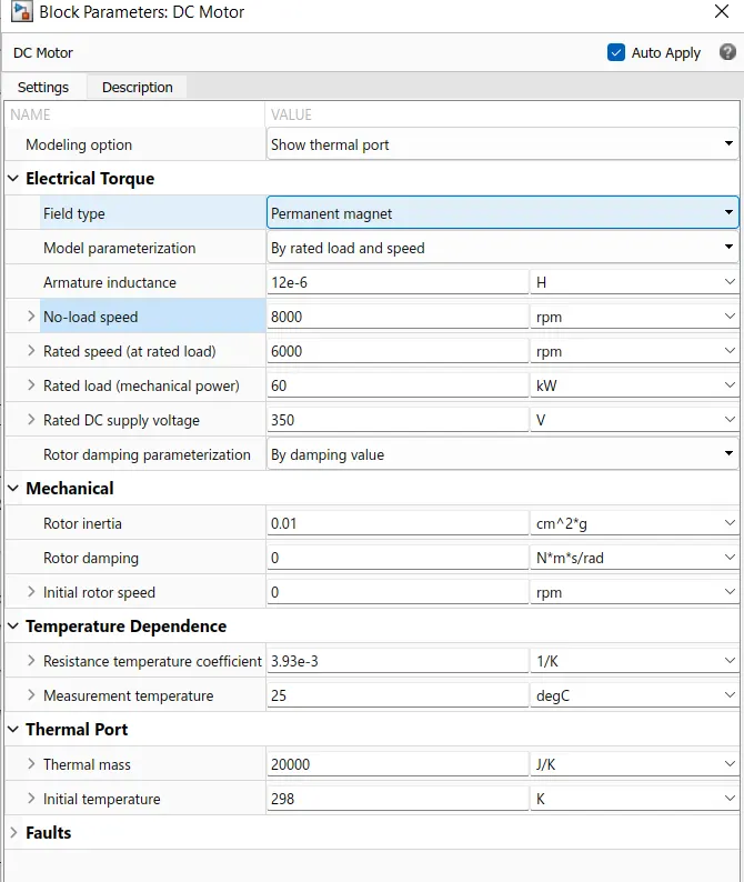
DC Motor(Brushed Type)-
The block assumes that no electromagnetic energy is lost, and hence the back-emf and torque constants have the same numerical value when in SI units. Motor parameters can either be specified directly, or derived from no-load speed and stall torque. If no information is available on armature inductance, this parameter can be set to some small non-zero value.
When a positive current flows from the electrical + to - ports, a positive torque acts from the mechanical C to R ports. Motor torque direction can be changed by altering the sign of the back-emf or torque constants.
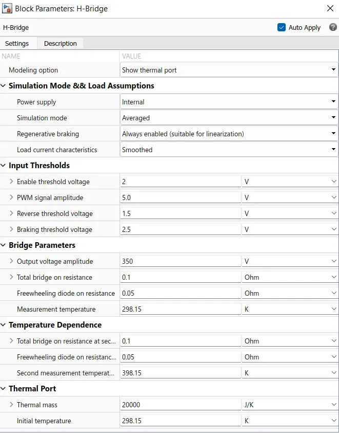
H-Bridge-
This block represents an H-bridge motor drive. The block can be driven by the Controlled PWM Voltage block in PWM or Averaged mode. In PWM mode, the motor is powered if the PWM port voltage is above the Enable threshold voltage. In Averaged mode, the PWM port voltage divided by the PWM signal amplitude parameter defines the ratio of the on-time to the PWM period. Using this ratio and assumptions about the load, the block applies an average voltage to the load that achieves the correct average load current.
For this model, Averaged mode is selected.
Temperature Sensor:
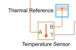
Temperature Sensor is used to mesure the temperature of H-Bridge and Motor. This block measures temperature in a thermal network. There is no heat flow through the sensor. The physical signal port T reports the temperature difference across the sensor. The measurement is positive when the temperature at port A is greater than the temperature at port B.
Controlled Voltage Source-
The block represents an ideal voltage source that is powerful enough to maintain the specified voltage at its output regardless of the current passing through it. The output voltage is V = Vs, where Vs is the numerical value presented at the physical signal port.
Controlled Current Source-
Converts the Simulink input signal into an equivalent current source. The generated current is driven by the input signal of the block.
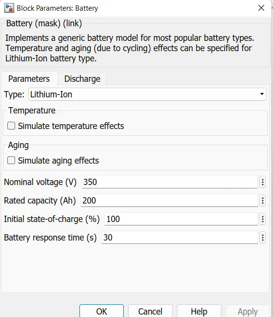
Battery-
The battery type chosen is Lithium-ion Battery.
Controlled PWM Voltage-
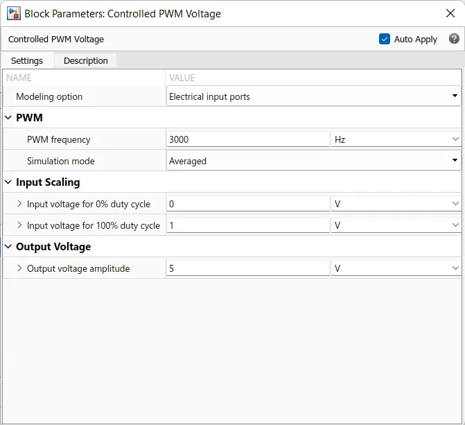
This block creates a Pulse-Width Modulated (PWM) voltage across the PWM and REF ports. The output voltage is zero when the pulse is low, and is equal to the Output voltage amplitude parameter when high. Duty cycle is set by the input value. At time zero, the pulse is initialized as high unless the duty cycle is set to zero or the Pulse delay time is greater than zero.
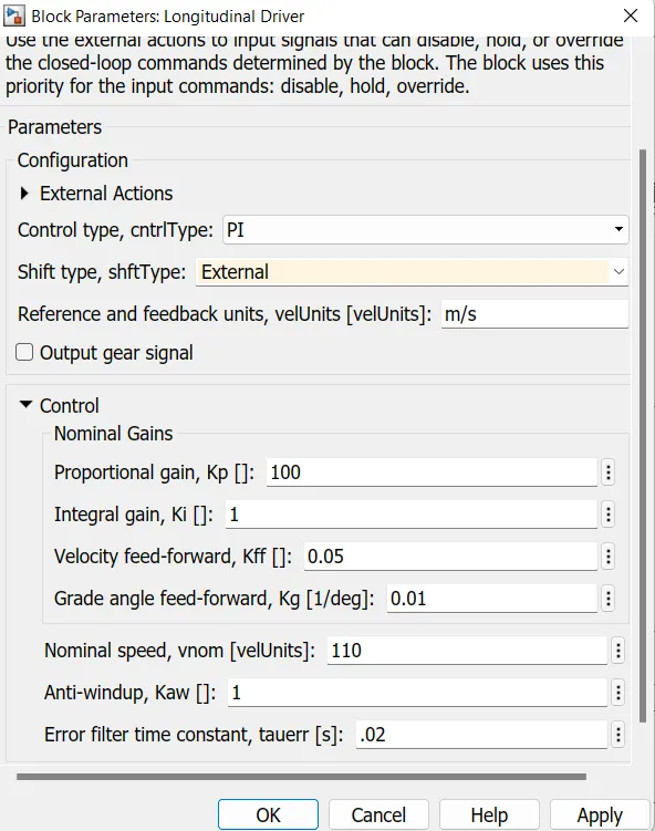
Longitudinal Driver-
Drive Cycle Source-
FTP 75:
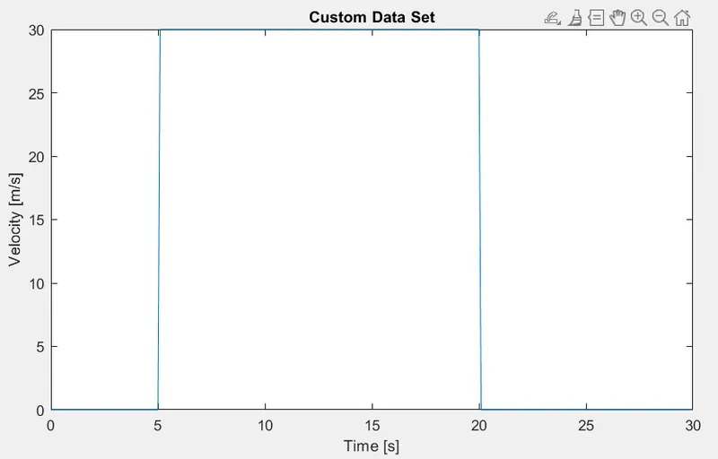
WOT:
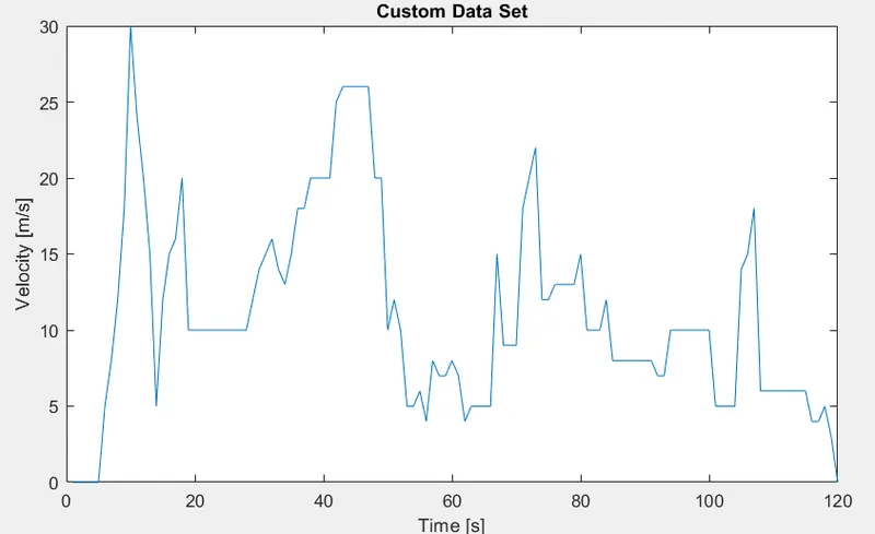
User-made drive cycle:
Drive cycle for 1 hour vehicle run at constant 45 kmph speed:
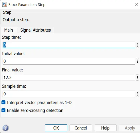
The speed of 45 kmph is converted to 12.5 m/s for 8000 seconds.
Multiport Switch-
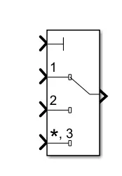
Pass through the input signals corresponding to the truncated value of the first input. The inputs are numbered top to bottom (or left to right). The first input port is the control port. The other input ports are data ports.
Results:
FTP 75:
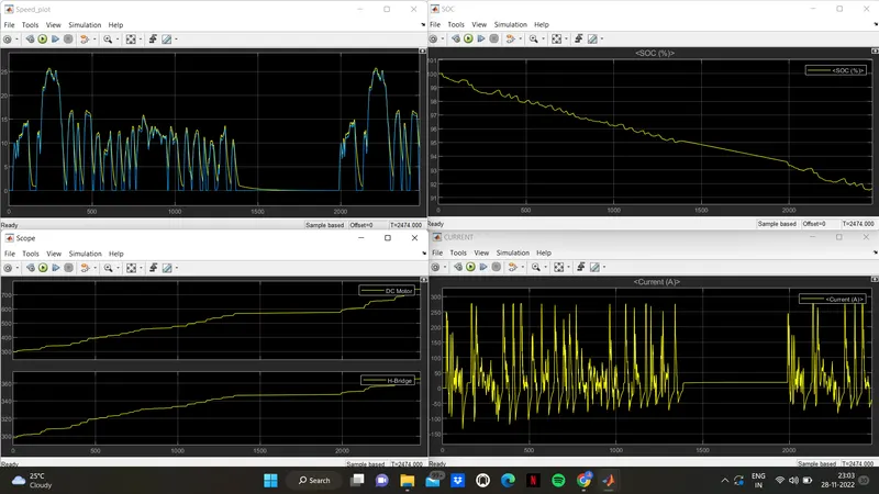
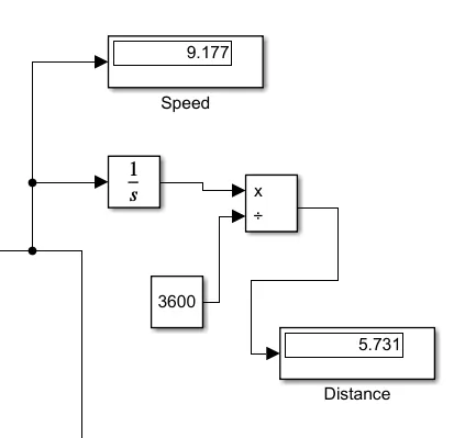
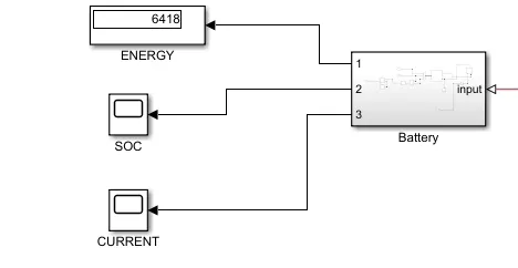
- Above results shows the speed, SOC, temperature,current plots and distance travelled for FTP 75 drive cycle.
- The distance travlled by the vehicle is 5.73 km at 9.17 m/s speed.
- The battery SOC drops from 100 to 90.5%.
- The DC motor temperature rises to 700 K and H-Brige temperature to 370 K.
- The current value varies according to acceleration and deceleration of the vehicle.
- The energy consumed by the battery is 6418 Wh.
WOT:
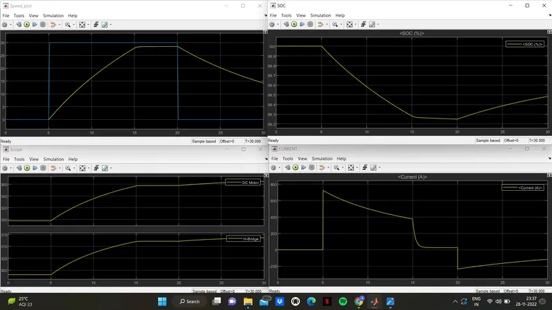
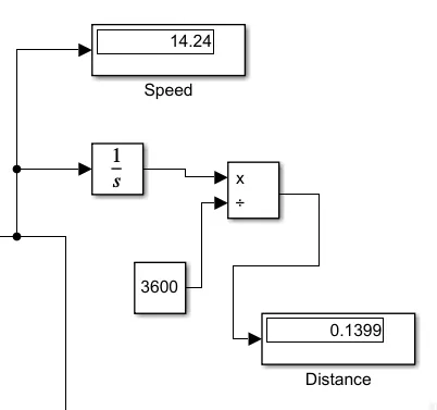
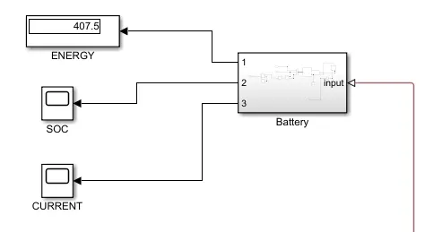
- Above results shows the speed, SOC, temperature,current plots and distance travelled for WOT drive cycle.
- The distance travlled by the vehicle is 0.14 km at 14.2 m/s speed.
- The battery SOC drops from 100 to 99.2%.
- The DC motor temperature rises to 360 K and H-Brige temperature to 315 K.
- The current value varies according to acceleration and deceleration of the vehicle.
- The energy consumed by the battery is 407.5 Wh.
User-made drive cycle:
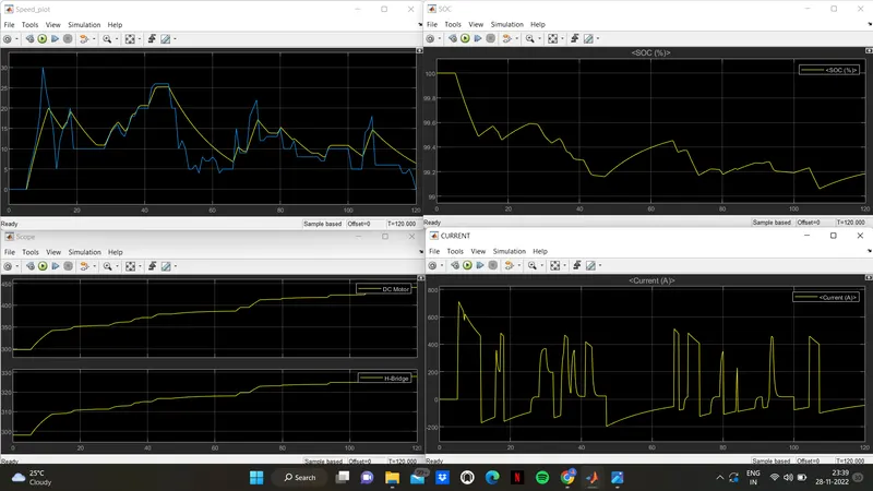
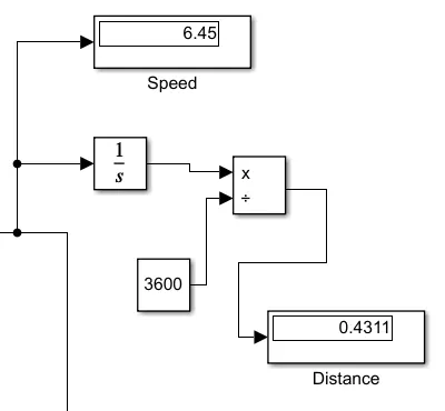
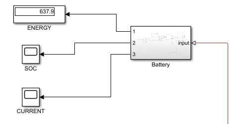
- Above results shows the speed, SOC, temperature,current plots and distance travelled for user-made drive cycle.
- The distance travlled by the vehicle is 6.45 km at 6.45 m/s speed.
- The battery SOC drops from 100 to 99%.
- The DC motor temperature rises to 450 K and H-Brige temperature to 330 K.
- The current value varies according to acceleration and deceleration of the vehicle.
- The energy consumed by the battery is 638 Wh.
Drive cycle for 45 kmph constant speed for 1 hour:
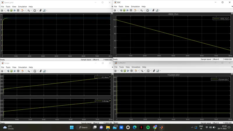
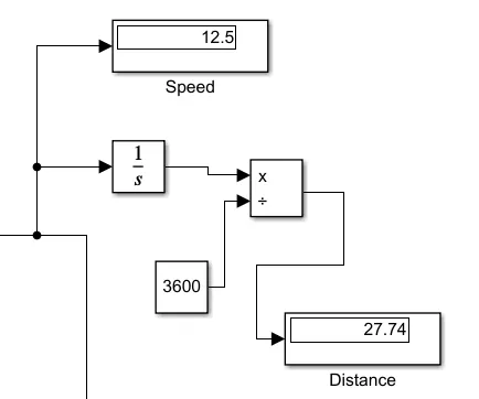
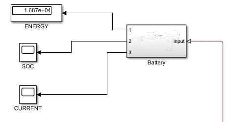
- Above results shows the speed, SOC, temperature,current plots and distance travelled for constant speed drive cycle.
- The distance travlled by the vehicle is 27.74 km at 12.5 m/s speed.
- The battery SOC drops from 100 to 75%.
- The DC motor temperature rises to 400 K and H-Brige temperature to 320 K.
- There is no change is current since the vehicle runs at constant speed.
- The energy consumed by the battery is 16.8 kWh.
Conclusion:
- The vehicle is modelled as rear wheels are driven by PM brushed type motor.
- The thermal mass of motor controller and DC motor is assumed and the temperature of the same is obtained for each drive cycle.
- The enegry consumed by the battery at the end every drive cycle is obtained.
- All the input and assumed data is stored in an excel sheet.