Final Project: Electric Rickshaw modelling
Aim: To Create a detailed MATLAB model of an electric rickshaw (three wheel passenger vehicle) as per details below
Main objectives:
Rear wheels driven by PM brushed type motor
Assume efficiency points of motor controller and motor
Make an excel sheet of all input and assumed data
Results: For any three standard driving cycles show energy consumption, temperature rise of motor and controller for 100 km constant speed driving at 45 kmph
Methodology:
- The electric vehicle mainly consist of a battery motors and controller then it generates a power
- So to design any vehicle first we need to calculate the propulsion power then the motor is to be selected
- In last step based on the motor rating or operating range or no km/ charge we want to depend on evrything battery capacity and then the battery capcity is selected
Introduction:
- The electric E- rickshaw is aslo know as the electric tuk-tuk e-rickshaw and aslo auto tgis are becoming popular after year 2017 in the indain market
- This E- rickshaw is the best alternative to the petrol or CNG gas auto rickshaw because of there low fuel cost zero emissions and less human effort
- The electric system mainly designed in the indian is 48v Dc which can run 90-100km/full charge
- The top speed is 25km/hr and this electric motor power ranging from the 650-1400w
- The battery takes 8-10hrs to fully charged the seating capacity is driver+ 4 passengers so total 5
- So here the e-rickshaw is designed in CREO and MATLAB simulink in the designed electric rickshaw main bocks are battery DC motor vehicle body and transmission drive cycle
- Here drive cycle is the input of the human effort this is how going to drive this actual cycle we can use drive cycle like FTP75,WOT or by using excel
- Here our main objective of this project is to obtain the speed by the driver to estimate the temperature of the motor and controller to calculate the SOC and distance travel by the vehicle
- Here we have SOC block to calculate the sate of charge of the battery distance is calculated by speed and time paramter for all the three drive cycles
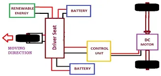
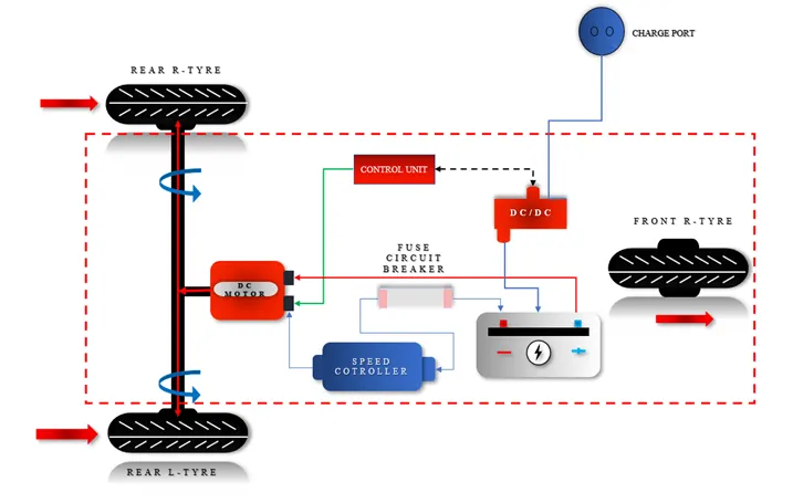
Genaral deatils of the E-Rickshaw:
1) Battery type: lithium-ion 330v75
2) vehicle kerb weight 260 kgs
3) load capacity 340 kgs
4) vehicle speed 7kmph
5) driving range 140 km (160ah)
6)no of wheels per axel 2
7)frontal area 91 m
8) drag coefficeient 5 wheel radius 306m
9) vertical load 3000N
10) nominal volatge 330v
11) rated capacity 75Ah
12) initial SOC 100%
13) internal resistance 5ohms
Procedure:
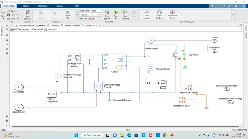
i) Power and motor controlled susbsystem model with the temperature sensor
ii) H-bridge:
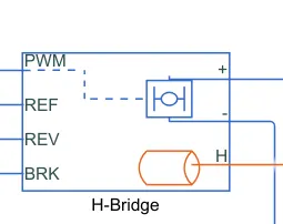
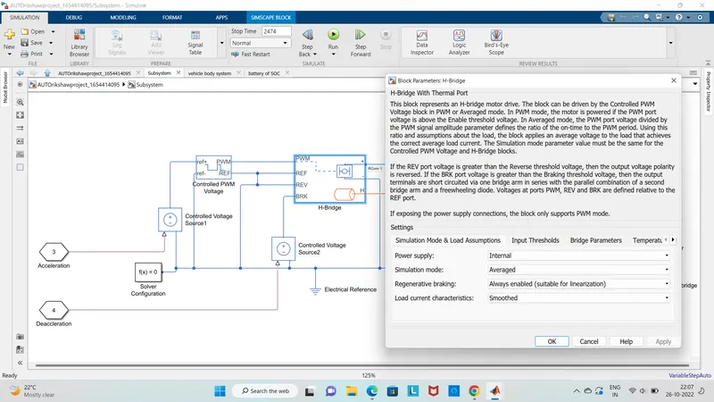
- The above block respresnts the an H-bridge motor drive
- This block can be used to driven by the controlled PWM voltage block in PWM or avergae mode
- In this PWM mode the motor is powered if the PWM port volatge is above the enable volatge
- But in averaged mode the PWM port volatge is divided by the PWM singnal amplitude paramter which gives the ratio of the on time to PWM required period
- By using this ratio and load assumptions about the block applies an averge volatge to the load
- This will achive the correct average load current
- The simulation mode paramters value must be the same for the controlled PWM voltage and H-bridge
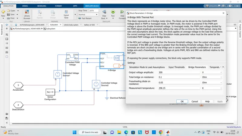
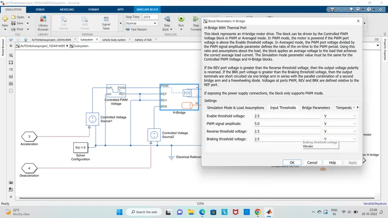
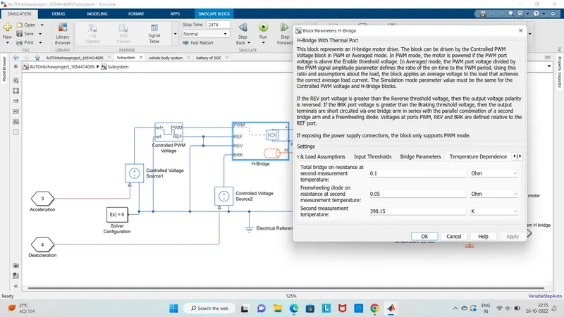
- Here if the REV port voltage is greater than the reverse threshold volatge then the output volatge polarity is reversed
- If the BRK port voltage is greater than the braking voltage then the output will be short circuited through one bridge arm in series with the paralle combination od the second bridge arm and with a freewheeling diode
- The volatge at the ports PWM REV BRK are defined relative to the REF port if we exposing the power supply connections the block only supports pwm mode
iii) D.C motor:
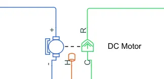
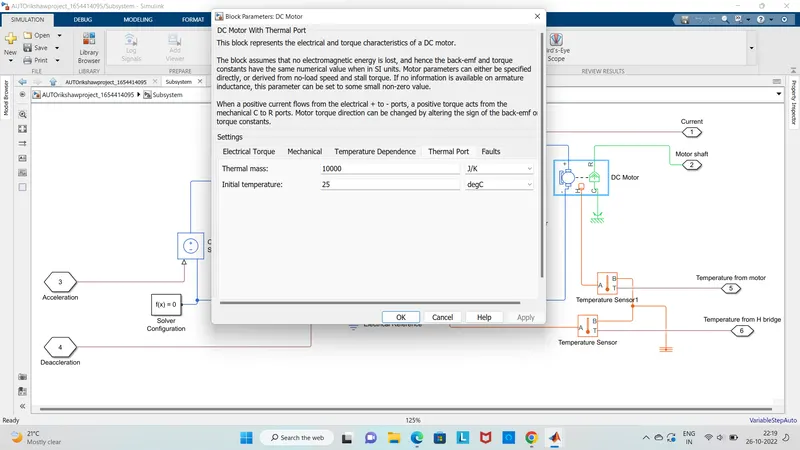
- The above block represents the electrical and torque charcterstics of the DC motor which aslo inculdes the therma port to series with the temperature of the motor
- This manly assumes that there is no electromagnetic energy is lost and hence the back emf and torque constants have the same numerical values
- Here the motor paramters can be specified or directly derived from the no load speed and torque if there is no info is available on the armature inductance this paramter can be set to the small non zero value
- If when the postive current flows from the electrical ports a postive torque acts from the mechincal C TO R ports
- The motor torque direction can be changed by changing sign of the back emf pr the torque constants
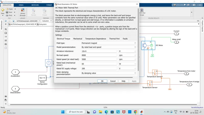
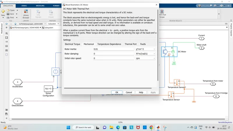
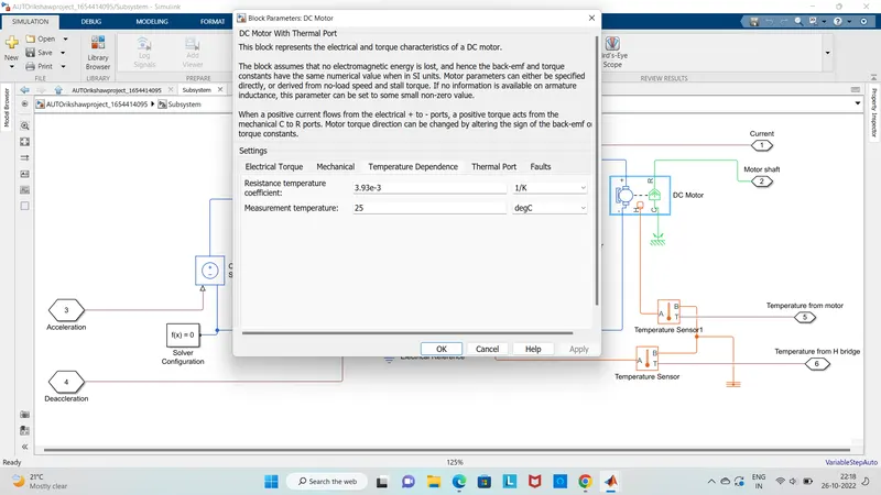
- Here the motor controller will get the input from the longitudinal driver
- Its main function are to control the speed of the motor and drive according to the input of the driver
- Here mainly motor controlled we designed consist of two parts name as PWM volatge and H -bridge input 1 is getting from the accelmd of the longitudinal driver and its given to a controlled voltage source block wher its input to controlled PWM volatge will genrate a PWM signal in such way the H bridge will genrate the required voltage to operate the DC motor for the given driver input
- The PWM volatge block negative reference and ref are grounded and REF of the H bridge ,Here the H bridge is a motor controller that has IGBT components which operates only two at the time to the input of the siginal from the PWM block
- If when the deceleration occurs this H brideg will given an output from the positve and negative terminals of it
- This negative and postive terminals are then connected to the DC motor battery
- By all thes componets are simscape electrical componets so they need a connection to the slover configuration block which helps ti slove the simulation easily
iv) Controlled PWM volatge:
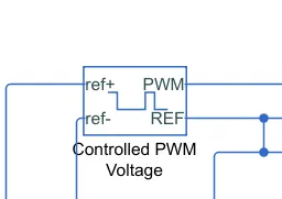
- The above block mainly creates a pluse width moudlated PWM volatge across the PWM and REF ports
- The output volatge is zero when the pluse is low and is equal to the output voltage amplitude paramter when high
- Here the duty cycle is set by the input value by right clicking block and selects simscape block chices to switch between electrical ref/ -ref ports and ps input u to specify the input values
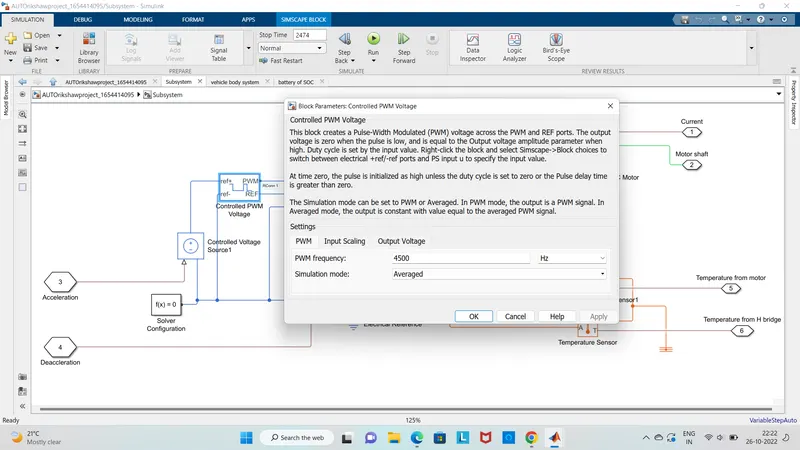
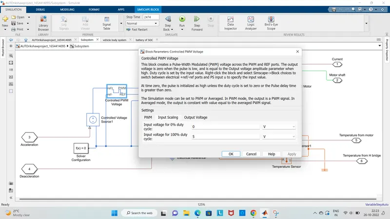
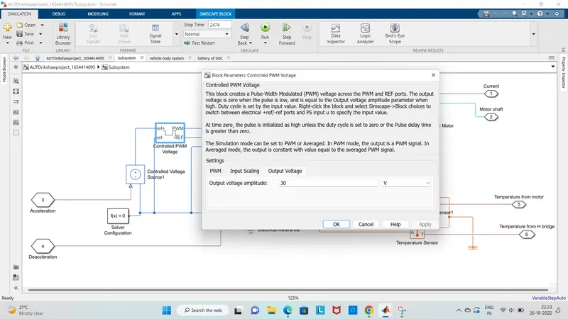
When the time is zero the pulse is initialized as the high unless the duty cycle is set to zero or the pulse delay time is greater than zero
Here the simulation mode can be set to pwm or averged .in PWMmode the output is a PWM siginal where as in Averged mode the output is constant with the value equal to the averged PWM signal so slected the simulation mode as averaged
V) Temperature sensor:
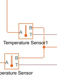
- This sensor is mainly used to measure the temperature of the H bridge and the motor
- This block measures temperature in a thermal network there is no heat flow through the senosr
- The physical signal port T reports the temperature difference across the sensor
- The measurement is postive when the temperature at port A is greater that the temp at port B
Vii) slover configuration:
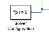
It mainly defines the slover settings for the simulation
2 Vehicle body subsystem model:
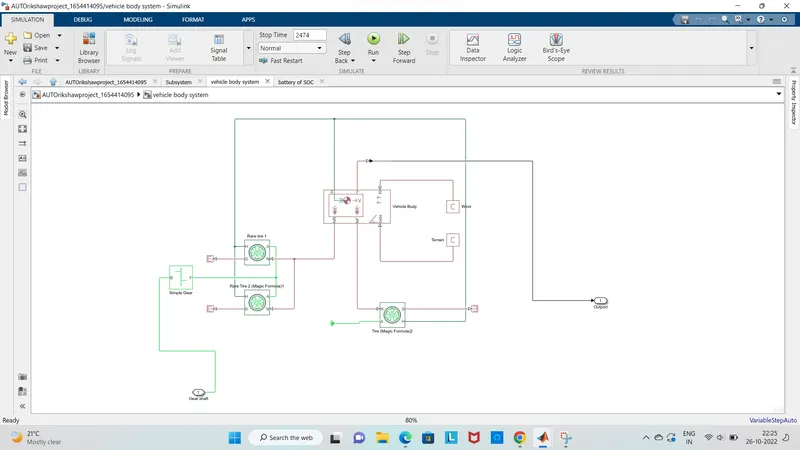
- The above digram shows that how is it is inside the vehiclebody and transmission system and the main design it is mainly referred just only as a transmission system
- Here we created a rear whell drive transmission system
- The motor will produce the rotational output which will given to the vehicle body and transmission system
- This rotational output is taken buy the gear system here to maintatin the constant speed through the transmission losses in speed from the motor to tires
- Here the gear output is given to the axel of rear tire in the circuit as shown above that gear is connected to the rear wheels and the front wheels is free to rotational motion so by this vehicle moves forward
- Here N is the normal force caused by the tires and it is given to thevehicle bodys normal force port
- The vehicle body as an H hub s-tire slip N normal force as the axel connection wind velocity inclination angle
- So the tire hub is connected as the common node to the vehicle body
- The vehicle body wind velocity is mainly connected to the constant block and the beat inclination angle is connected to another constant block
- Here we can assign wind velocity and inclination angle as per requirement
- The velocity output port were we can ger at which speed the vehicle is moving the velocity is taken out to get the distance traveled and soc
i) Tire:
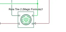
It mainly represents the logitudinal behaviour of the high way tire by the tire magic formula
This block is built from the tire road interaction and simscape foundation library wheel and axel blocks
The optionally the effect of tire inertia stfiness and damping can be included
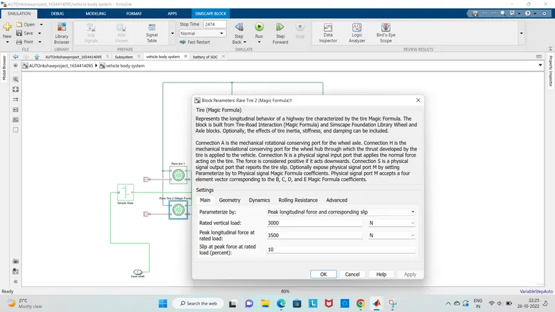
- Here the connection A is the mechincal rotational conserving port for the wheel axle
- connection H is the mechanical translational conserving port for the wheel hub thriugh which the trust developed by the tire is applied to the vehicle
- The connection N is the physical siginal input port which applies the normal force acting on the tire the force is considered as the postive if it acts downards
- Connection s is the physical siginal output port which reports the tire slip
- Physical siginal port M accepts a four element vector corresponding to the B C D and E magic formula
ii) Gear:
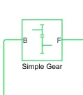
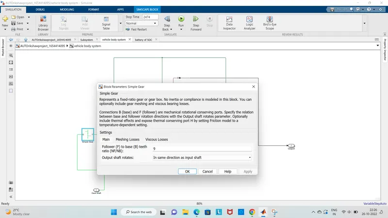
The above figure represents the fixed ratio gear or gear box there is no inertia is compliance is modeled in this block
The connection B and F are mechincal conserving ports which specify the relation between the base and flowwer roation directions with the output shaft rotates
It aslo has theraml effects and expose thermal conserving port H by right clickng on the block and selecting simscape block choices to switch between various output shaft rotates in the same direction of the input shaft
Here the base is connected to the motor shaft and follower is connected to the rear wheel drive
iii) Vehicle body:
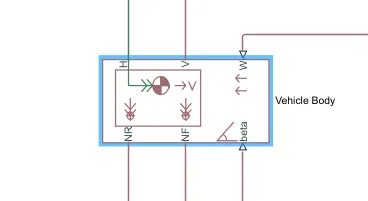
- The above block is represents a two axle vehicle body in longitudinal motion
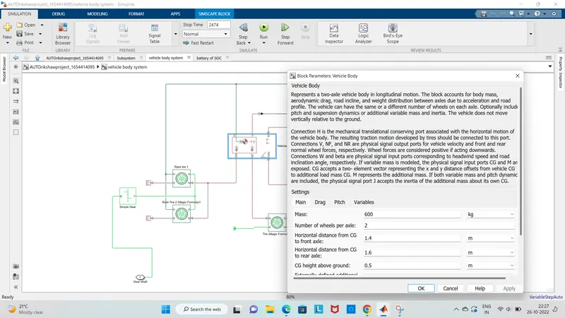
- the block accounts for the body mass aerodynamic drag road incline weight disturbution between the axels due to accelertion of the road
- here the connection H is the mechincal translational consrving port hub NF and NR corrsepond to the output ports for normal reactions forces on the front axle and rear axle wheels
- The connection V represents the actual output translational velocity of the vehicle beta is the road inclination angle and W cirresponds to the headwind speed
- The gross weight is given as 600 kg the geometric paramter of the vehicle are given as
3 ) Battery and SOC sub system model:
i) Battery:
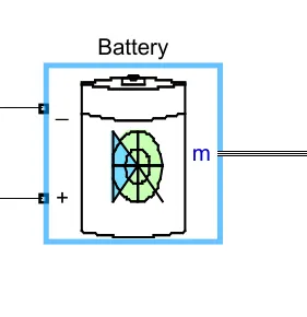
The battery is mainly used to power the controller and motor the controller uses the battery power according to produced the input given by the motor to get maximum speeed
The battery is also used to power every electrical component in the vehicle
The battery block mainly implements the genric dynamic model which represents the mot popular types of rechargable batteries
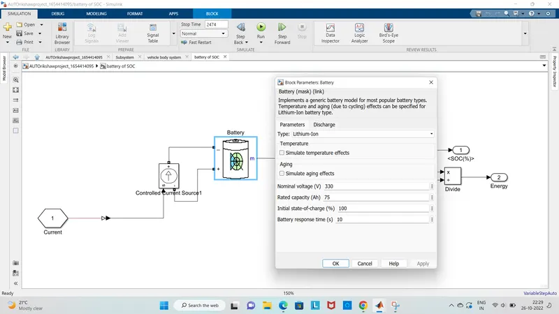
Here the battery as two stage one is charging and other is dicharging state
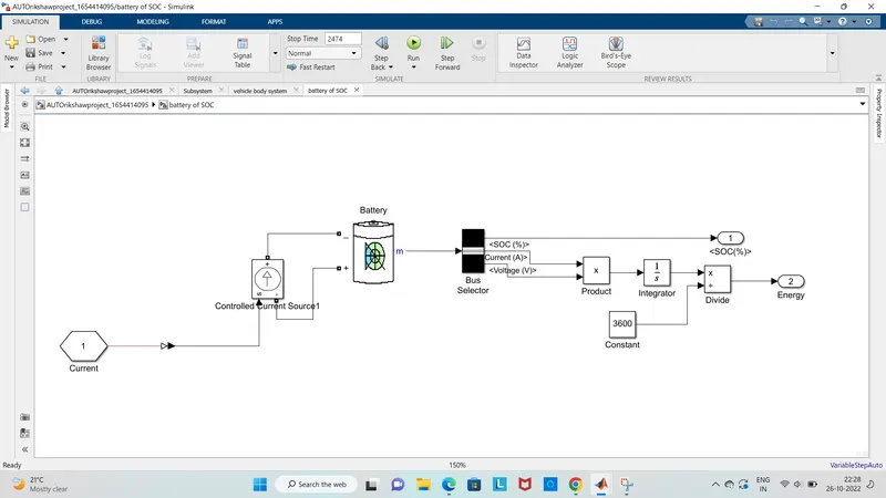
the battery is 75Ah capacity and the nominal voltage of the battery is 330 v the intial SOC is 100%
Here SOC is the percentage or level of a battery presents after certain travel or consumption of battery charge by the vehicle
In the designed vehicle battery charge or SOC is calculated by giving it to the rate of transition and then to gain where 1/nominal battery capacity then to discrete time integrator and it will get minus from the 1 as it is consdered a 100% of the battery and it is multipiled with 100% of battery
ii) Controlled current source:
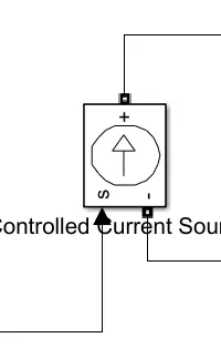
- The above block shows the controlled current source which converts the simulink input siginal into an current source
- This genrated current is drven by the input siginal of the block
- The postivedirection is as shown by the arrow in the block icon
- Here we can slo initilize the controlled current source block with the specific AC or DC
- If we want to start the simulation in stead sate the block input must be connected to a siginal starting as a sinusodial or DC wave form ehich responsble to the initial values
- BY double clicking on he controlled current from the drop dowm menu of measurement select current
iii) Bus selector:
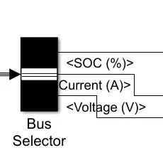
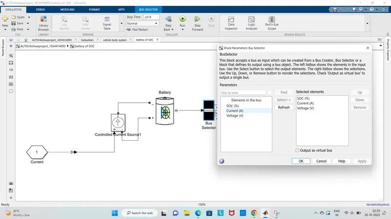
Here the bus selctor block mainly represents the output of siginals you select from the input bus
the block can output the selected elements separately or in a new bus
Here we need to just mange the output and conect it with different scope block
IV) Power GUI:
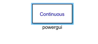
This powerful block allows us to chosse the one of these methods to slove
continous or discretization
The powerful block aslo opens tools for steady state and simulation results analysis and advance paprmeter
4) Longitudinal driver:
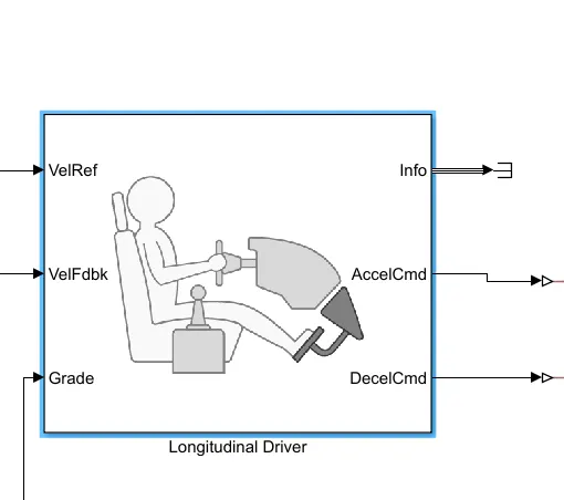
- It is a in bulit block provided by the powertrain blocks
- It is aspeed tracking controller for genrating normlized acceleration and braking commands based on the reference and feed back velocities
- The VelFdbk port is responsible to the feedback velocity so the actual veloicty output given by the vehicle body is connected here
- Grade is responsible to the grade angle for this simulation there is no inclinations so it is not considered
- Info gives the output for the bus siginal for different block calcualtions like difference in ref vehicle speed and vehicle speed
- Accel Cmd and DecekCmd are responsible for acceleration and deceleration commands generated and connected to the corresponding ports of the controlled PWm voltage block
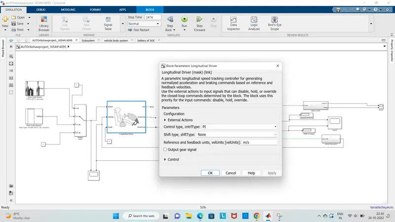
- Her the slected control type is PI so the block implements proportional intergral control with the tracking windup and feed forward gains
5) Reference velocity (drive cycle):
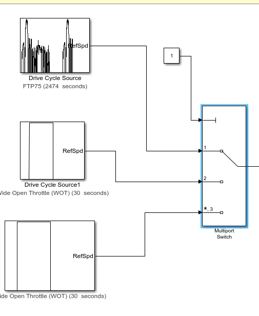
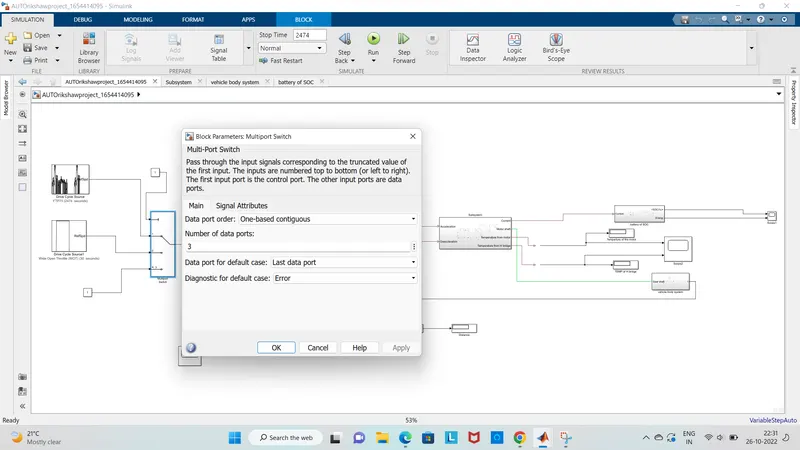
Here the drive cycle is assumed as the driver input of a vehicle and it is replaced how a driver will drive a vehicle
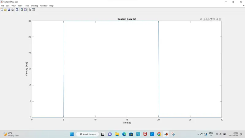
here we have used two different drive cycle they are FTP75 and WOT
FTP drive cycle:
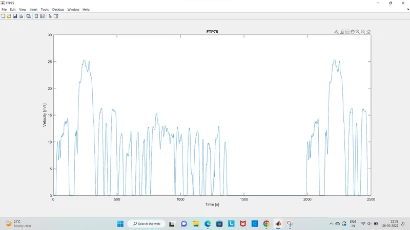
This generates a standard specified longitudinal drive cycle
we can aslo import the drive cycle from the predefined sources and workspace variables and alo #mat ,xlsx xls txt files
Wide open throttle:
Entire simulink model :
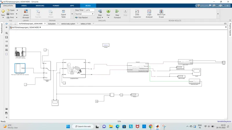
Here intially the current flow to DC motor from the battery through the DC-DC power converter to drive the motor
The required voltage will be controlled in the controller the controller will follow the given drive cycle reference and run the motor to required rpm
Then the motor power is transmitted to the wheels of a vehicle through the gear box and controller will take the vehicle speed and compare and control
Output results:
1) For FTP75drive cycle:
Here by running the vehicle with the ftp75 drive cycle for 2474 we get the below results and the distance travelled is 57.8
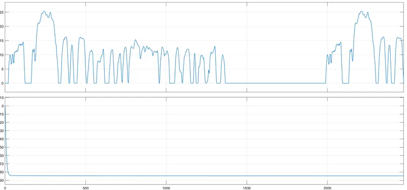
As from the above we can see that the velocity profile alomost completely following drive cycle data with the maximum speed reaching up to 25km/hr
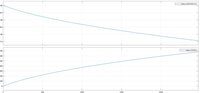
The SOC for the battery drop to neraly 75% of its 100% value for the complete drive cycle it coverd distance is 57.8 km
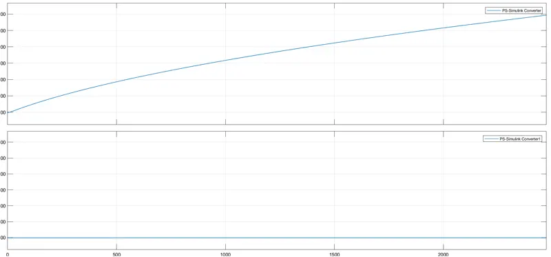
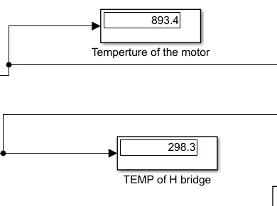
The temprature of themotor is increased to 893c and the tenperature of the controller is 298.3 with10000 as the thermal mass given both to the motor and the Hbridge
2) For WOT drive cycle:
By running the vehicle with the WOT drive cyclefor 30 sec we get the distance travelled is 0.5378
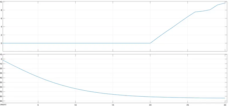
scope 2 SOC:
The Soc battery reaches to full throttel vaule later the battery gets charged by the back emf
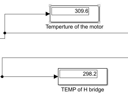
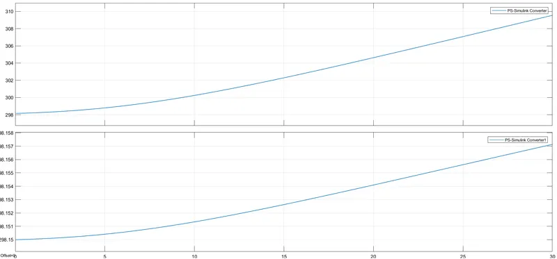
The temperature of the motor is increased to 309c and the temperature of the controller is 298c
CONCLUSION:
we have succesfully created a detailed MATLAB model of an electric rickshaw (three wheel passenger vehicle) as per details below:
Rear wheels driven by PM brushed type motor
Assume efficiency points of motor controller and motor
we aslo detrimed the varation of temperature of motor controller SOC and energy consumed by the vehicle for all the two reference drive cycles
This battery powerd rickshaw will be the most popular mode of transport in the upcoming days