Final Project: Electric Rickshaw modelling
Aim : To design a simulink model of Electric Rickshaw with DC motor and battery
Objective :
Rear wheels driven by PM brushed type motor
Assume efficiency points of motor controller and motor
Make an excel sheet of all input and assumed data
Results: For any three standard driving cycles show energy consumption, temperature rise of motor and controller for 100 km constant speed driving at 45 kmph.
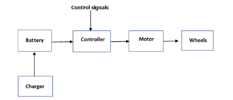
Block diagram of powertrain components in Electric Rickshaw :
Parameters assumed for designing the simulink model is attached in the form of excel sheet.
Considering the forces acting on electric rickshaw
- Rolling Resistance Force
- Aerodynamic Drag Force
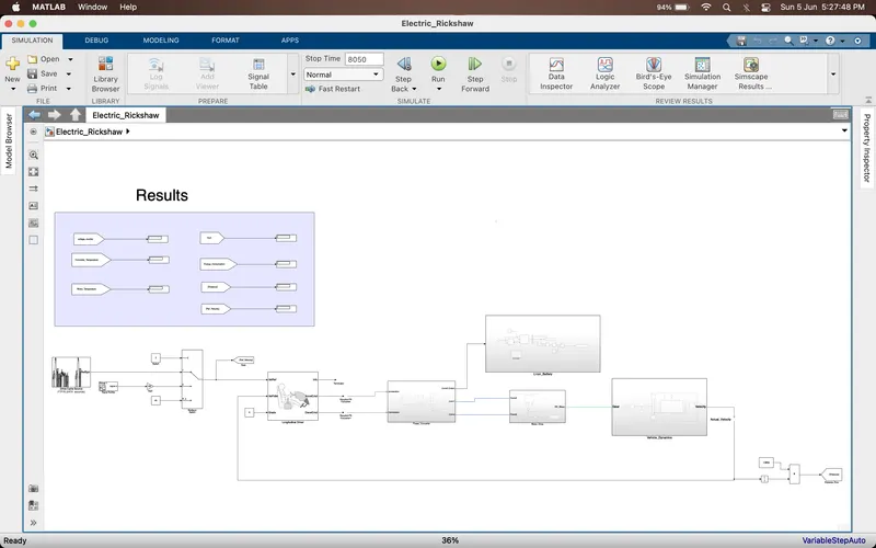
Model Designed :
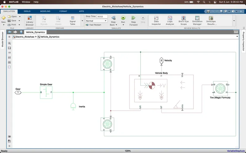
Vehicle Dynamics Subsytem :
Where,
H – Hub, all are connected to 3 tyres respectively with the vehicle body hub
A – Axle, Rear axle is connected with 2 tyres and front axle with 1 tyres
N – force applied, input force by the vehicle body and N are connected in 2 ways respectively i.e., rear and front axle
NR- Rear output force from the vehicle body, its given as an input to rear axle
NF- Front output force from the vehicle body, its given as an input to front axle
V- velocity
w- wind speed
beta – angle of inclination on road
B – gear input from the driver
F-output and it’s connected to rear axle because it’s a rear-wheel-drive vehicle, if front wheel drive, then connected to front axle.
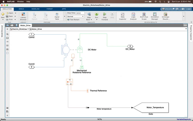
Motor Drive subsytem :
Using DC Motor with permanent magnet configurations and temperature sensor to measure the temperature of motor
Where,
C is torque is connected to mechanical rotation reference
R is torque which connected as input to gear
Positive is given to current sensor
Negative is given to Electrical reference
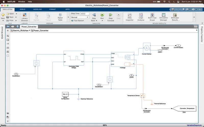
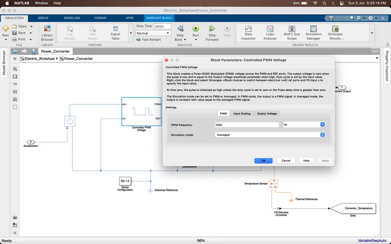
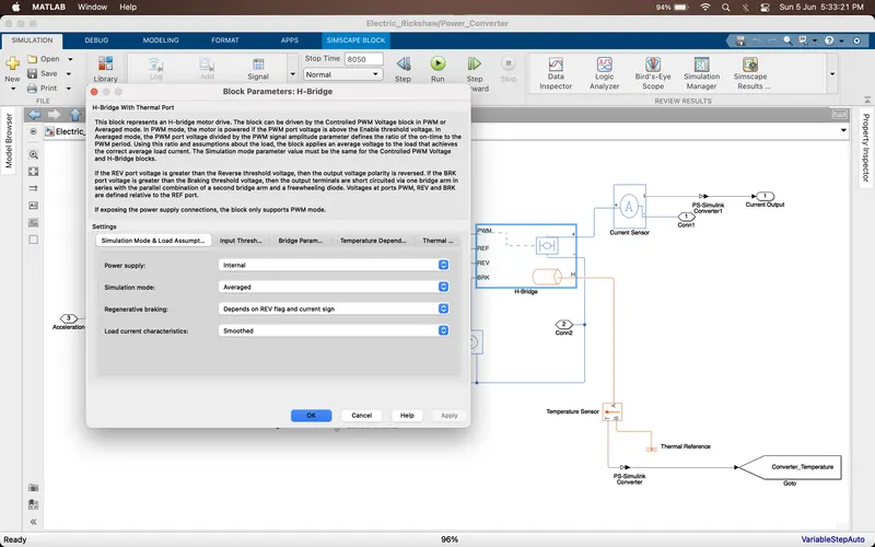
Power Converter Circuit: It is series combination of H- bridge and Controlled PWM voltage source and to measure the temperature using a temperature sensor
PWM frequency: 1000 Hz
H-bridge parameters are chosen according
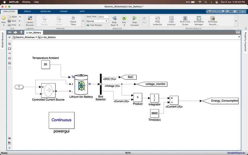
Battery Pack:
Longitudinal Driver:
Info details is terminated
Acceleration is given as input to Controlled PWM voltage source
Deceleration is given as input to the H bridge as braking threshold voltage through a voltage-controlled source
Grade: 0
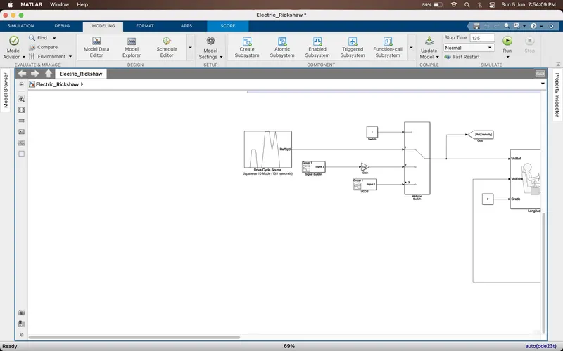
Veh Ref is Drive cycle
Vehicle velocity is given as the input to vehicle feedback
To calculate distance integrator is used and divide by 3600 to get the value in kms
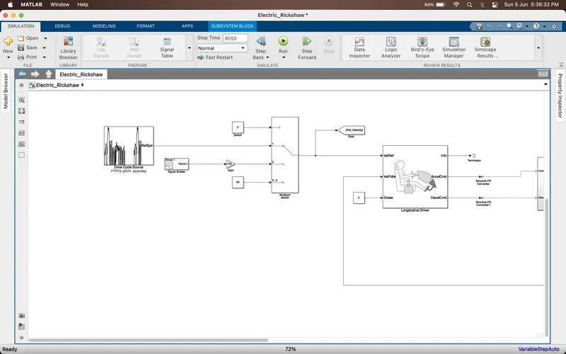
The function blocks used are as follows:
- Drive Cycle
- Constants
- Longitudinal Driver Block
- Terminator
- Simulink PS converter
- PS Simulink converter
- Mechanical Rotation Reference
- Electrical Reference
- Solver Configuration
- Controlled voltage source
- Controlled current source
- Controlled current sensor
- Temperature Sensor
- Thermal Reference
- Li-ion Battery
- Gain
- Product
- Sum function
- Bus Selector
- Controlled PWM Voltage
- H bridge
- DC Motor
- Vehicle Body
- Tires
- Simple Gear
- Integrator
- Divide Function
- Multiport Switch
- Signal Builder
- Goto & From Tags
- Scope
- Display
Output:
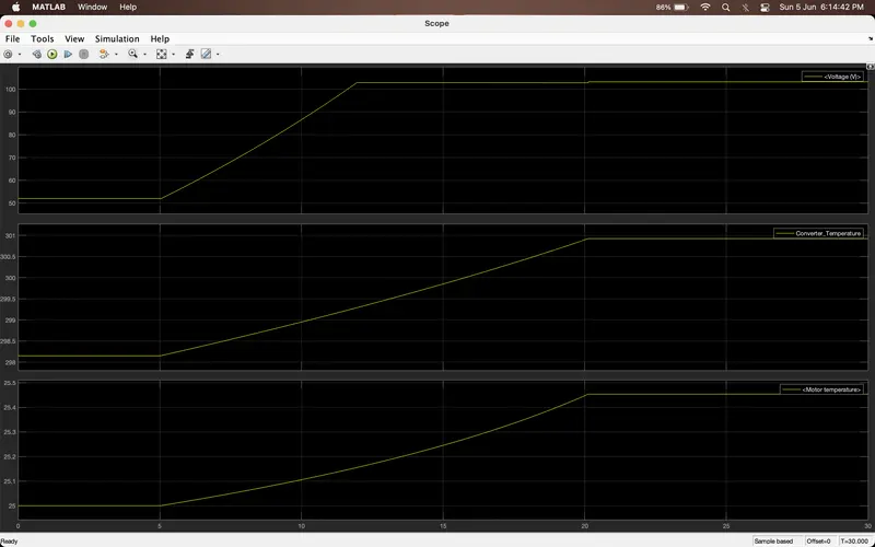
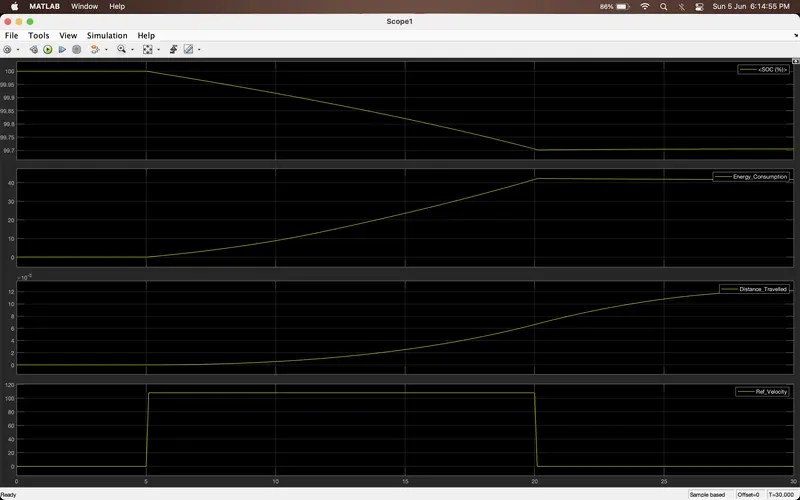
For WOT, Simulation for 30 seconds
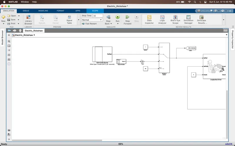
Results :
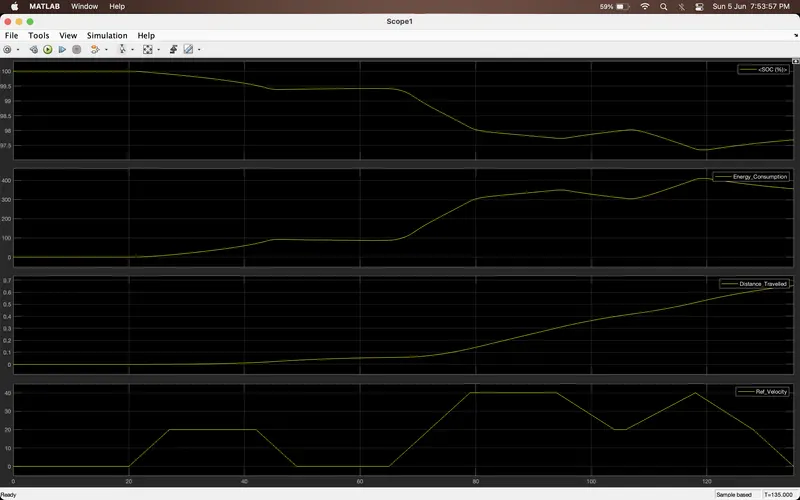
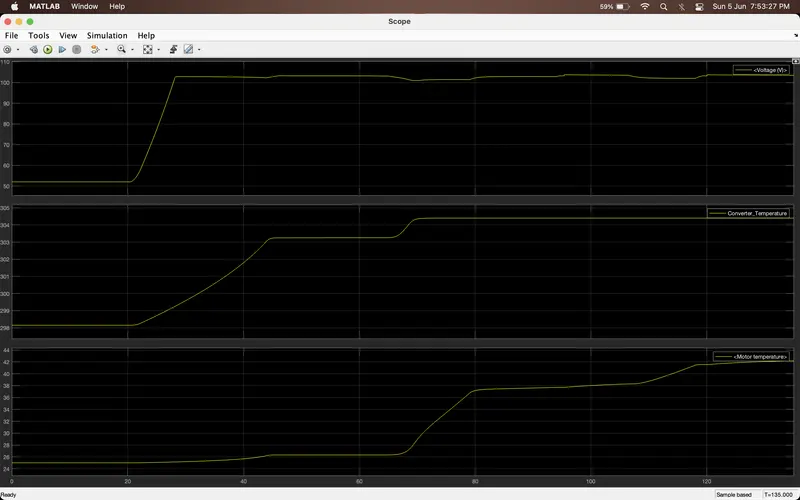
For Japanese 10 Mode, Simulation for 135 seconds
Results :
For Japanese 15 Mode, Simulation for 231 seconds
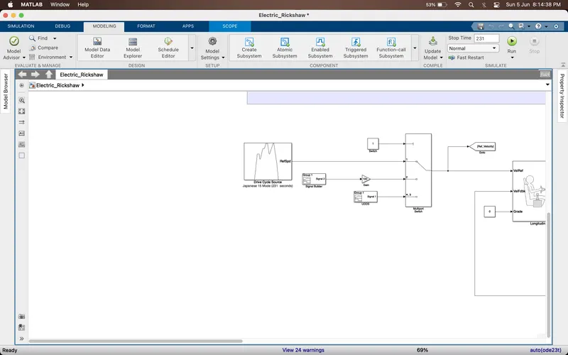
Results :
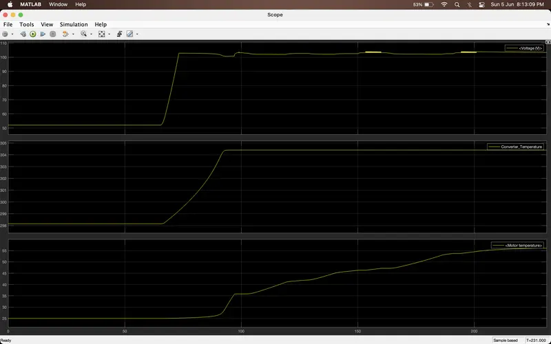
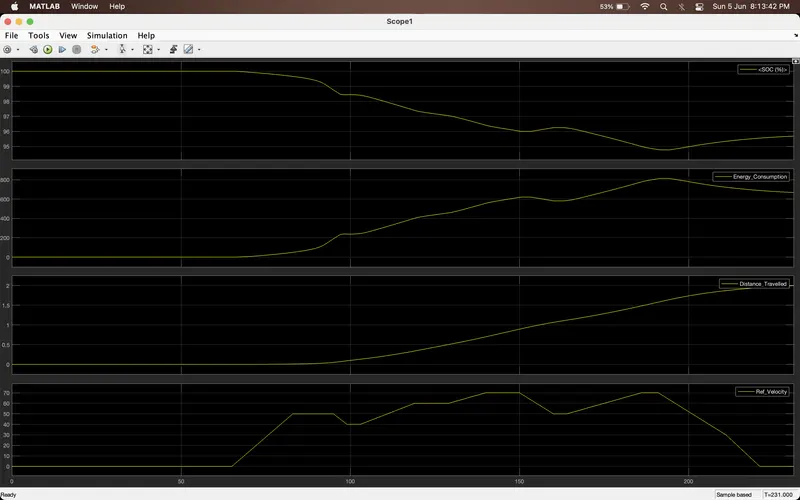
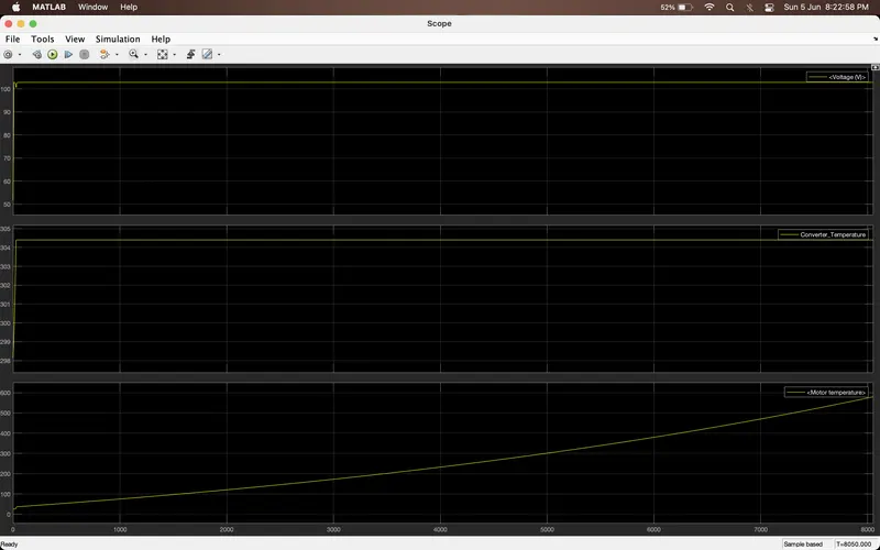
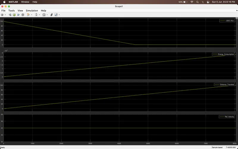
At 45 kmph for 100 kms
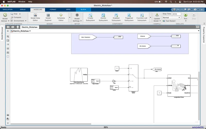
Simulation time = (100*3600)/45 =8000 seconds
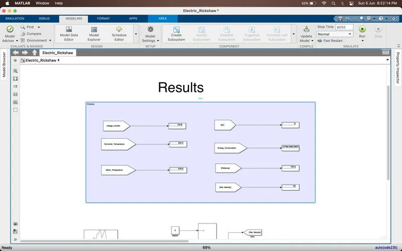
Results :
| Drive Cycle | Energy Consumption in Wh | Motor Temperature in deg | Controller Temperature in deg | Distance Travelled in kms |
| Wot | 41.72 | 25.45 | 300.9 | 0.012 |
| Japanese 10 Mode | 355.8 | 42.19 | 304.4 | 0.65 |
| Japanese 15 Mode | 668 | 56.04 | 304.4 | 1.997 |
| Condition | 27768.20 | 579.3 | 304.4 | 100.3 |
Conclusion :
- If the vehicle is designed for the same specifications as the matlab there would be some changes in the results depending on the surrounding and driver usage.
- Various parameters can be changed for better efficiency and improvement of the vehicle like Battery,mass of the vehicle,tyres, motor specifications etc.