Final Project: Electric Rickshaw modelling
ELECTRIC RICKSHAW MODELLING
OBJECTIVES:
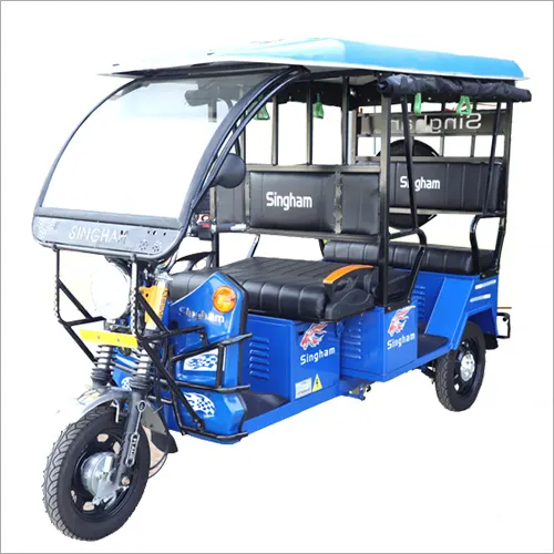
Create a detailed MATLAB model of an electric rickshaw (three wheel passenger vehicle) as per details below:
Rear wheels driven by PM brushed type motor
Assume efficiency points of motor controller and motor
Make an excel sheet of all input and assumed data
Results: For any three standard driving cycles show energy consumption, temperature rise of motor and controller for 100 km constant speed driving at 45 kmph.
SIMULINK MODEL OF ELECTRIC RICKSHAW:
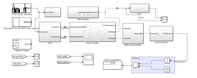
Model consist of FTP75 drive cycle, WOT cycle, 45Kmph for 100Km drive cycle, PID controller, H-Bridge, Permanent magnet DC motor, Vehicle body, Li-ion battery, gear system. Let we dive deep to the model.
Drive cycle:
FTP75
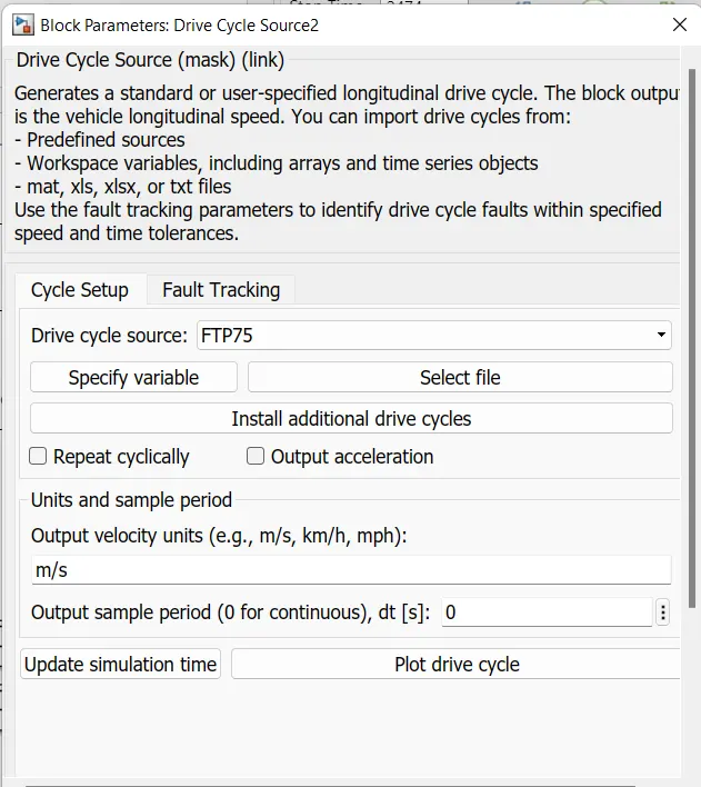
WOT
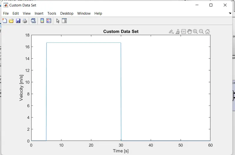
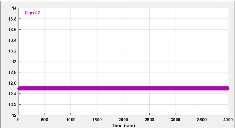
45Kmph for 100Km drive cycle:
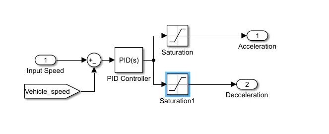
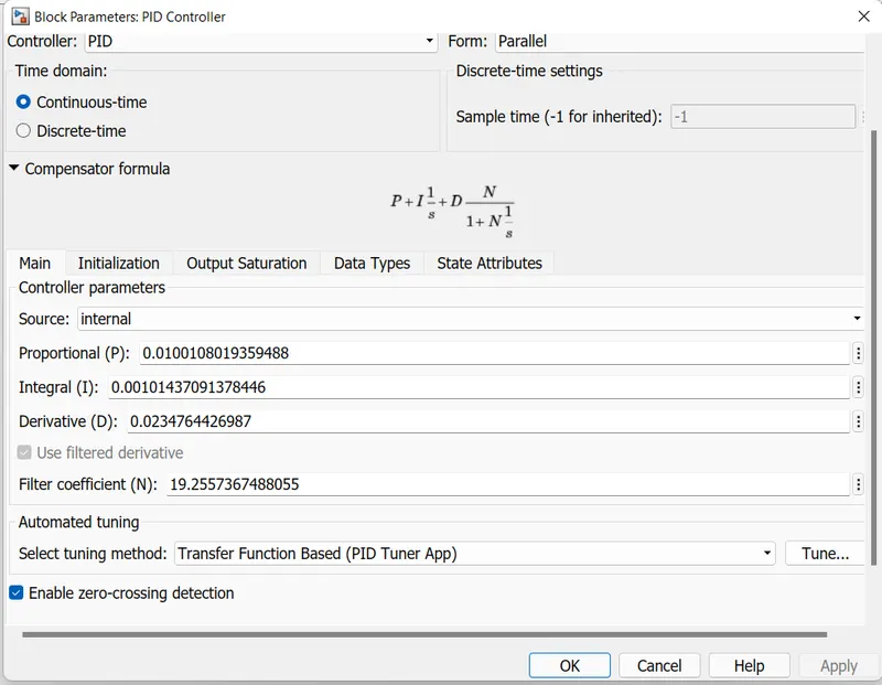
The reference speed and vehicle speed error is fed to PID. And the PID is tuned
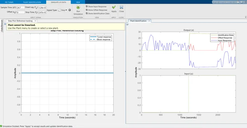
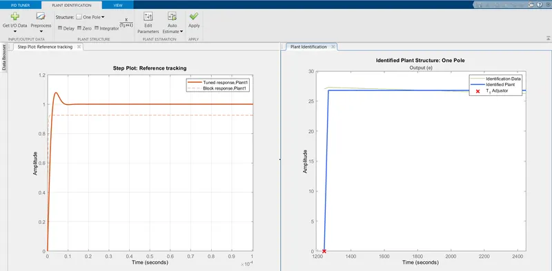
PID block is tuned to get the desired output
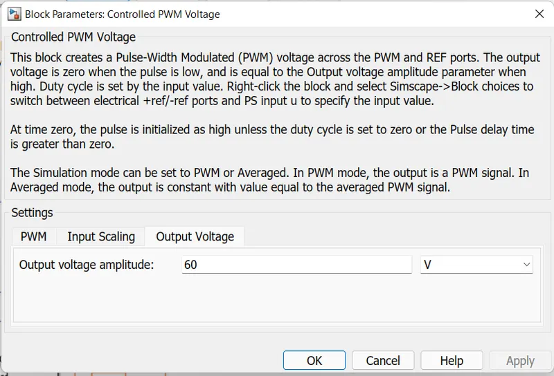
PID is connected to saturation block where the limits are minimized to -0.5 to 0.5. Where the saturation acts as a duty cycle varied between -0.5 to 0.5 and where the acceleration is fed to controlled PWM voltage and deceleration is fed to brake port of H-Bridge. Controlled PWM voltage block creates a Pulse-Width Modulated (PWM) voltage across the PWM and REF ports. The output voltage is zero when the pulse is low, and is equal to the Output voltage amplitude parameter when high.
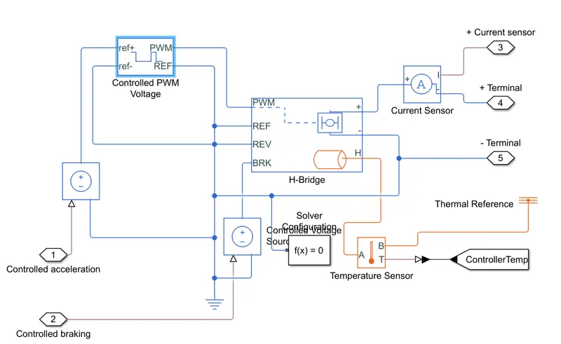
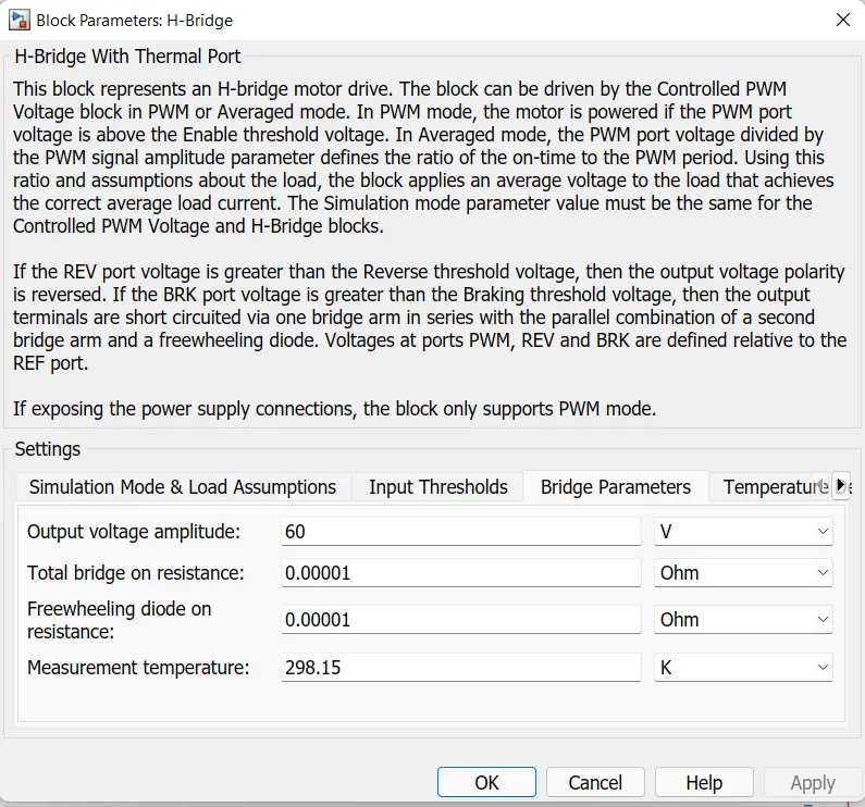
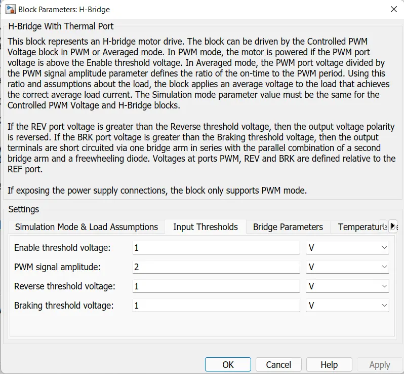
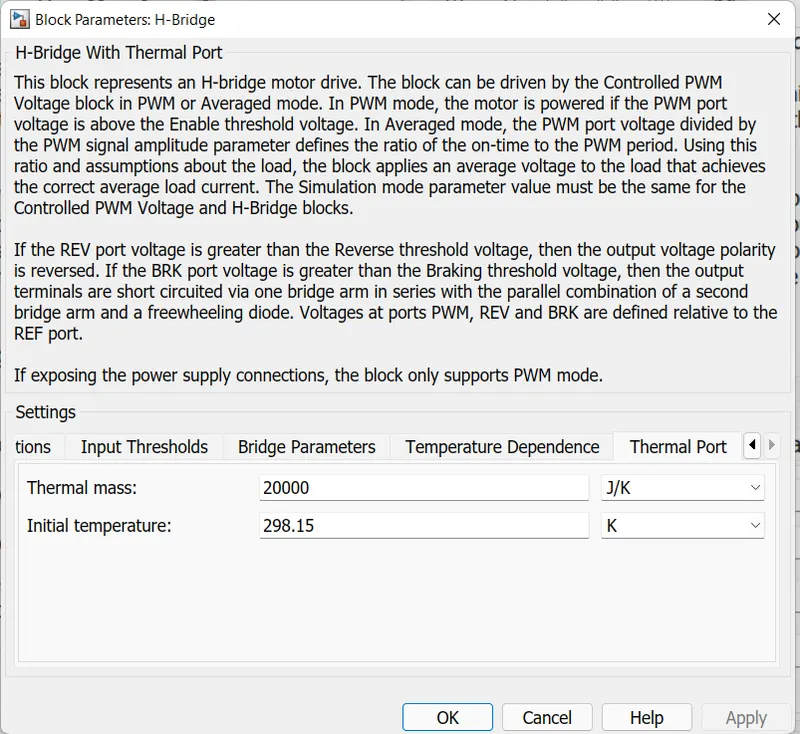
Temperature sensors are connected to monitor the temperature of power controller. Current sensor is connected across controller and motor to monitor the amount current drawn by the motor.
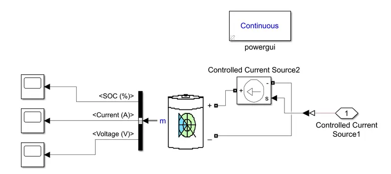
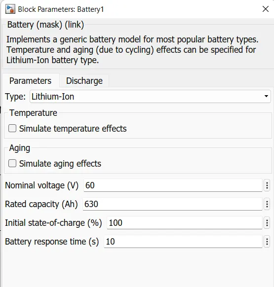
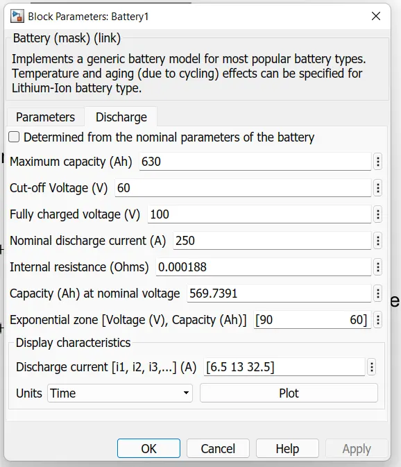
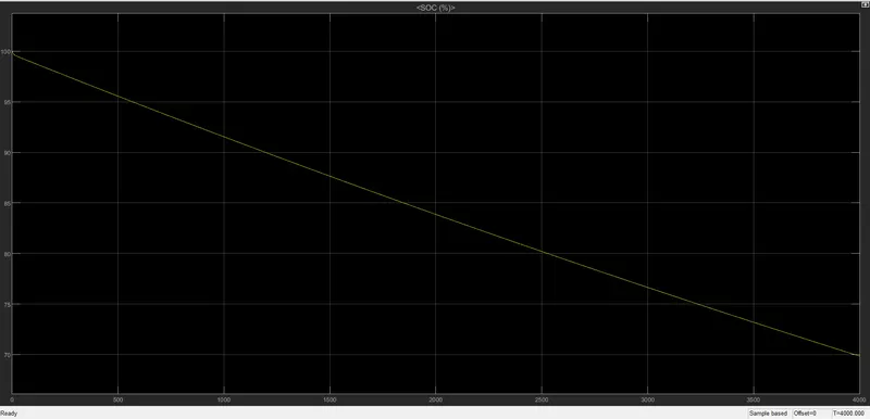
Through controlled current source Li-ion battery is connected. Through that SOC%, current, Voltage are determined.
SOC:
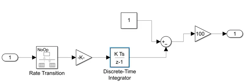
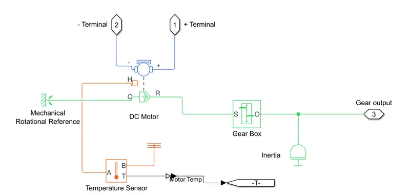
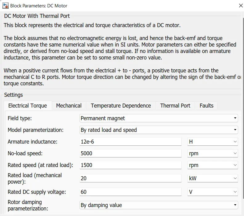
Terminals from the H-Bridge is connected to the permanent magnet brushed mtotor. And is connected to gear system where it will directly connect to the axle. To sense the temperature of motor a temperature sensor is connected.
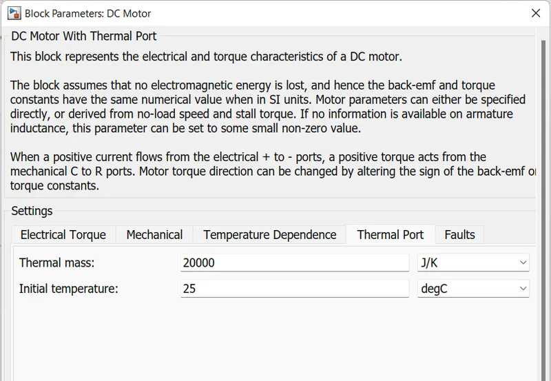
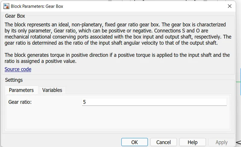
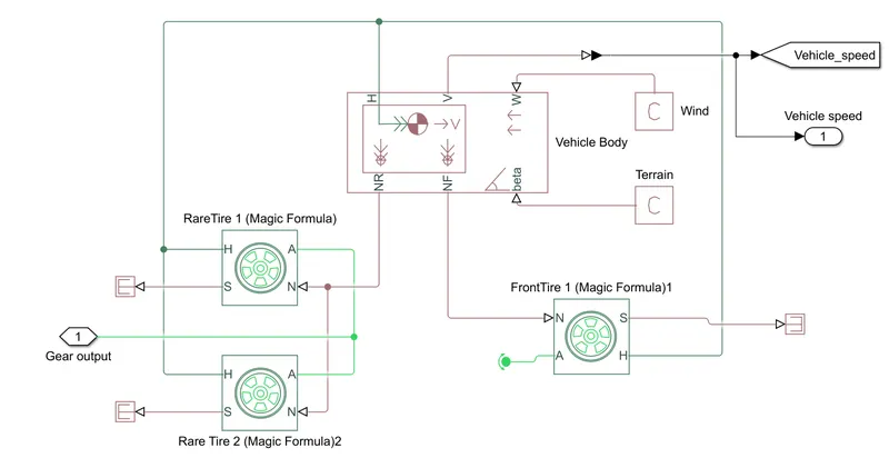
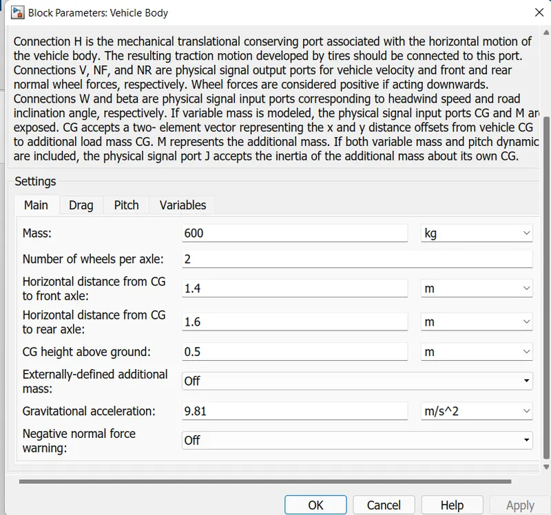
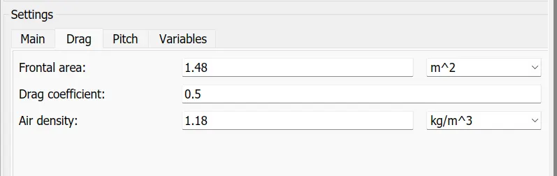
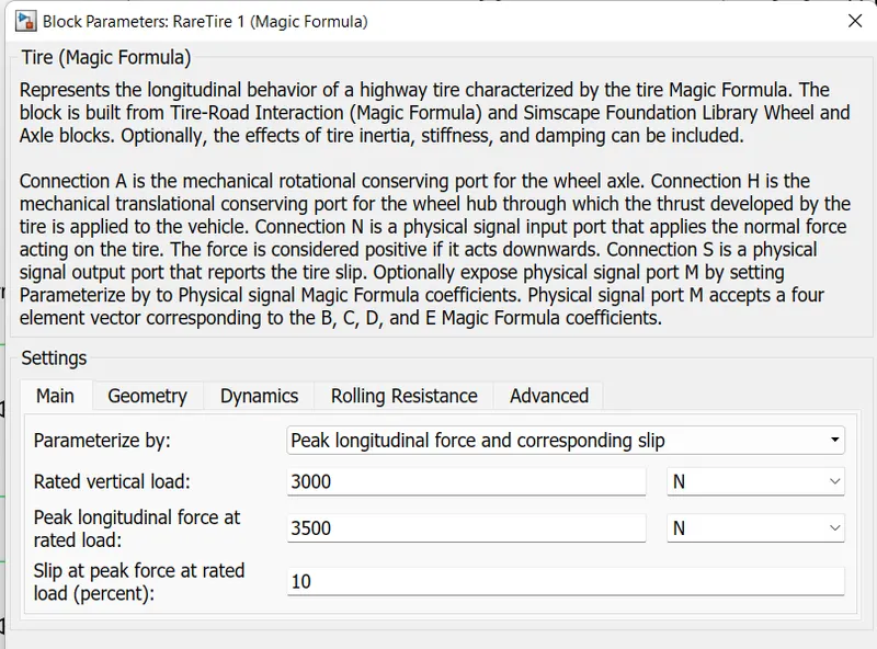
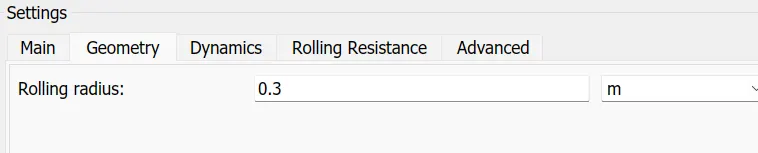
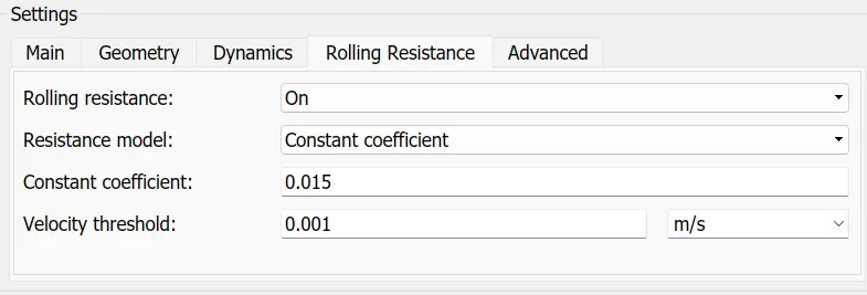
Gear out is connected to the axle of vehicle body, where the motor is connected to rear part of the vehicle body. There are totally 3 tires connected, wind velocity, inclination angles are added.
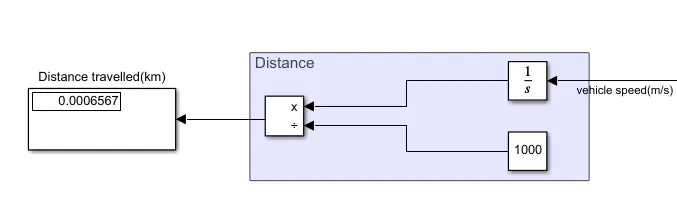
Distance is calculated by integrating the vehicle speed and dividing it with 1000.
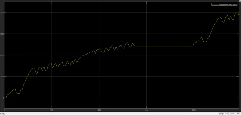
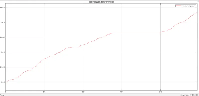
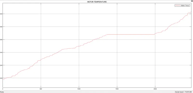
WHEN USING FTP75 DRIVE CYCLE:
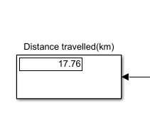
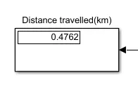
Distance travelled is
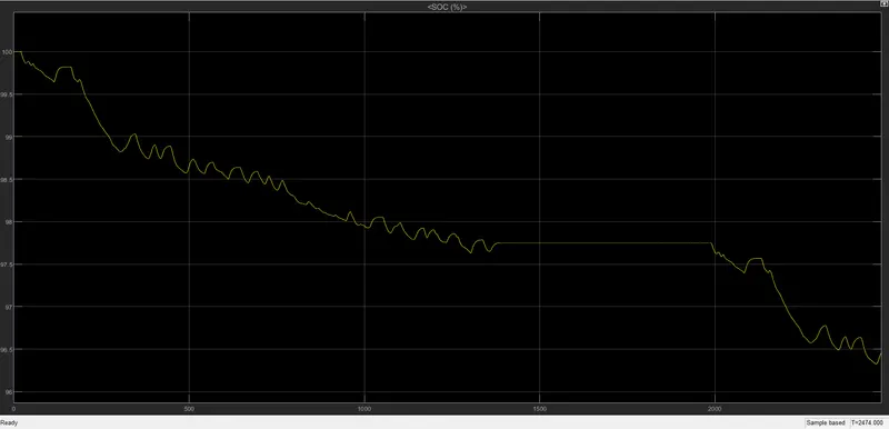
SOC:
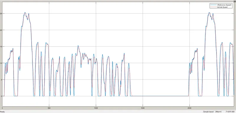
REFERENCE SPEED VS VEHICLE SPEED:
ENERRGY CONSUMED(WH):
CONTROLLER TEMPERATURE:
MOTOR TEMPERATURE:
WHEN USING WOT DRIVE CYCLE FOR 60SEC:
Distance travelled is
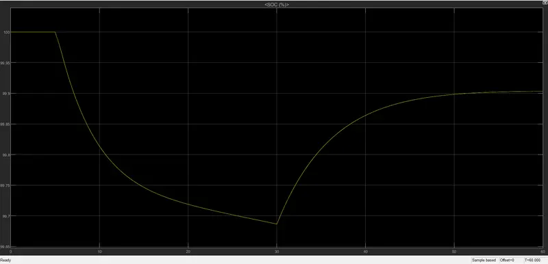
SOC:
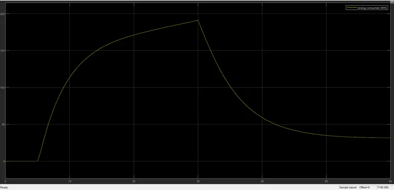
ENERGY CONSUMED IN WH:
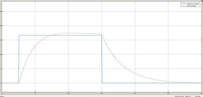
REFERENCE VS VEHICLE SPEED:
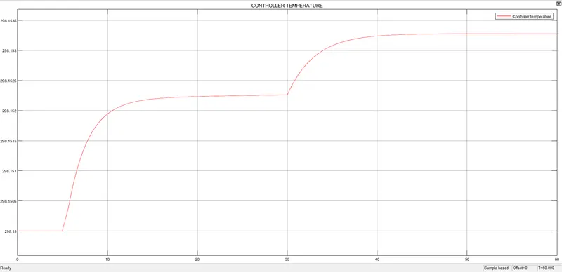
CONTROLLER TEMPERATURE:
MOTOR TEMPERATURE:
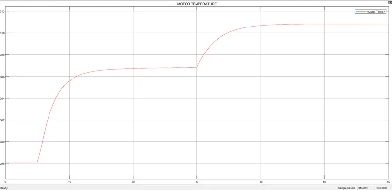
WHEN USING SIGNAL BUILDER 45Kmph for 100Km drive cycle:
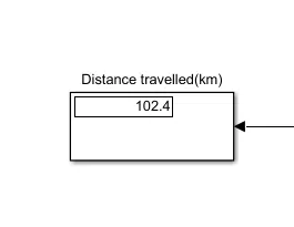
SOC:
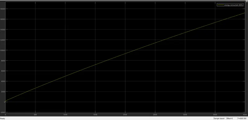
ENERGY CONSUMED IN WH:
REFERENCE SPEED VS VEHICLE SPEED:
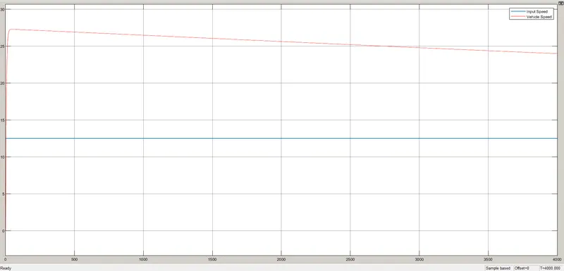
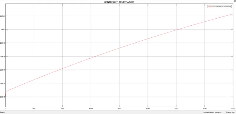
CONTROLLER TEMPERATURE:
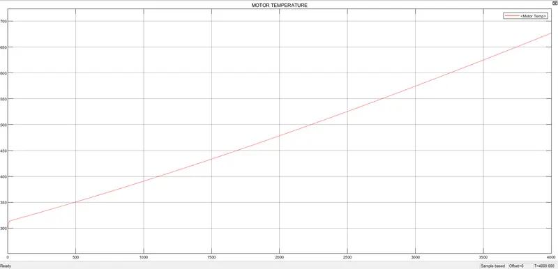
MOTOR TEMPERATURE:
RESULT:
For three standard driving cycles energy consumption, temperature rise of motor and controller for 100 km constant speed driving at 45 kmph are determined.