Project-1: Powertrain for aircraft in runways
Powertrain for aircraft in runways
1. Search and list out the total weight of various types of aircrafts.
Solution:
MTOW = Maximum take-off weight, MLW = Maximum landing weight, TOR = Take-off run , LR = Landing run
AIRPLANES:
| Type | MTOW [kg] | MLW [tonnes] | TOR [m] | LR [m] | ICAO category | FAA category |
|---|---|---|---|---|---|---|
| Antonov An-225 | 640,000 | 591.7 | 3500 | Heavy | Super | |
| Scaled Composites Model 351 Stratolaunch | 589,670 | 3660 | Heavy | Super | ||
| Airbus A380-800[1][2][3] | 575,000 | 394 | 3100 | 1930 | Super | Super |
| Boeing 747-8F | 447,700 | 346.091 | 3100 | 1800 | Heavy | Heavy |
| Boeing 747-8 | 443,613 | 306.175 | 3100 | Heavy | Heavy | |
| Boeing 747-400ER | 412,770 | 295.742 | 3090 | Heavy | Heavy | |
| Antonov An-124-100M | 405,060 | 330 | 2520 | 900 | Heavy | Heavy |
| Boeing 747-400 | 396,900 | 295.742 | 3018 | 2179 | Heavy | Heavy |
| Lockheed C-5 Galaxy[4][5][6] | 381,000 | 288.417 | 2530 | 1494 | Heavy | Heavy |
| Boeing 747-200[7] | 377,840 | 285.700 | 3338 | 2109 | Heavy | Heavy |
| Boeing 747-300[7] | 377,840 | 260.320 | 3222 | 1905 | Heavy | Heavy |
| Airbus A340-500[8] | 371,950 | 240 | 3050 | 2010 | Heavy | Heavy |
| Airbus A340-600[8] | 367,400 | 256 | 3100 | 2100 | Heavy | Heavy |
| Boeing 777F | 347,800 | 260.816 | 2830 | Heavy | Heavy | |
| Boeing 777-300ER | 351,800 | 251.29 | 3100 | Heavy | Heavy | |
| Boeing 777-200LR | 347,450 | 223.168 | 3000 | Heavy | Heavy | |
| Boeing 747-100[7] | 340,200 | 265.300 | Heavy | Heavy | ||
| Airbus A350-1000 | 308,000 | 233.5 | Heavy | Heavy | ||
| Boeing 777-300 | 299,370 | 237.683 | 3380 | Heavy | Heavy | |
| Boeing 777-200ER | 297,550 | 213.00 | 3380 | 1550 | Heavy | Heavy |
| Airbus A340-300[8][9] | 276,700 | 190 | 3000 | 1926 | Heavy | Heavy |
| McDonnell Douglas MD-11 | 273,300 | 185 | 2990 | 1890 | Heavy | Heavy |
| Airbus A350-900 | 270,000 | 175 | 2670 | 1860 | Heavy | Heavy |
| Ilyushin Il-96M | 270,000 | 195.04 | 3115 | 2118 | Heavy | Heavy |
| McDonnell Douglas DC-10 | 256,280 | 183 | 2990 | 1890 | Heavy | Heavy |
| Boeing 787-9[10] | 254,000 | 192.777 | 2900 | Heavy | Heavy | |
| Boeing 787-10[10] | 254,000 | 201.849 | Heavy | Heavy | ||
| Airbus A340-200[8][11] | 253,500 | 181 | 2990 | Heavy | Heavy | |
| Airbus A330-900 | 251,000 | 191,000 | 3100 | Heavy | Heavy | |
| Ilyushin IL-96-300 | 250,000 | 175 | 2600 | 1980 | Heavy | Heavy |
| Airbus A330-300[12][13] | 242,000 | 185 | 2500 | 1750 | Heavy | Heavy |
| Airbus A330-200[12][13] | 242,000 | 180 | 2220 | 1750 | Heavy | Heavy |
| Lockheed L-1011-500 | 231,300 | 166.92 | 2636 | Heavy | Heavy | |
| Boeing 787-8[10] | 228,000 | 172.365 | 3300 | 1695 | Heavy | Heavy |
| Lockheed L-1011-200 | 211,400 | Heavy | Heavy | |||
| Ilyushin IL-86 | 208,000 | 175 | Heavy | Heavy | ||
| Boeing 767-400ER | 204,000 | 158.758 | 3414 | Heavy | Heavy | |
| Airbus A300-600R[14] | 192,000 | 140 | 2385 | 1555 | Heavy | Heavy |
| Boeing 767-300ER | 187,000 | 136.08 | 2713 | 1676 | Heavy | Heavy |
| Concorde | 185,000 | 111.1 | 3440 | 2220 | Heavy | Heavy |
| Airbus A300-600[14] | 163,000 | 138 | 2324 | 1536 | Heavy | Heavy |
| Boeing 767-300 | 159,000 | 136.078 | 2713 | 1676 | Heavy | Heavy |
| Airbus A310-300[14] | 157,000 | 124 | 2290 | 1490 | Heavy | Heavy |
| Vickers VC10 | 152,000 | 151.9 | Heavy | Heavy | ||
| Boeing 707-320B[15] | 151,000 | 97.5 | Heavy | Heavy | ||
| Boeing 707-320C[15] | 151,000 | 112.1 | Heavy | Heavy | ||
| Douglas DC-8-61 | 147,000 | Heavy | Heavy | |||
| Airbus A310-200[14] | 142,000 | 123 | 1860 | 1480 | Heavy | Heavy |
| Airbus A400M | 141,000 | 122 | 980 | 770 | Heavy | Heavy |
| Douglas DC-8-32 | 140,000 | Heavy | Heavy | |||
| Douglas DC-8-51 | 125,000 | Medium | Large | |||
| Boeing 757-300 | 124,000 | 101.6 | 2550 | 1750 | Medium | Large |
| Boeing 707-120B[15] | 117,000 | 86.3 | Medium | Large | ||
| Boeing 757-200 | 116,000 | 89.9 | 2347 | 1555 | Medium | Large |
| Boeing 720B[16] | 106,000 | 79.5 | Medium | Large | ||
| Boeing 720[16] | 104,000 | 79.5 | Medium | Large | ||
| Tupolev Tu-154M | 104,000 | 80 | Medium | Large | ||
| Tupolev Tu-204SM | 104,000 | 87.5 | 2250 | Medium | Large | |
| Convair 880 | 87,500 | Medium | Large | |||
| Boeing 737-900 | 85,000 | 66.36 | 2500 | 1704 | Medium | Large |
| Boeing 737-900ER | 85,000 | 71.35 | 2804 | 1829 | Medium | Large |
| Boeing 727-200 Advanced[17] | 84,000 | 70.1 | Medium | Large | ||
| Airbus A321-100[18] | 83,000 | 77.8 | 2200 | 1540 | Medium | Large |
| Boeing 737-800 | 79,000 | 65.32 | 2308 | 1634 | Medium | Large |
| Boeing 727-200[17] | 78,000 | 68.1 | Medium | Large | ||
| McDonnell-Douglas MD-83 | 73,000 | 63.28 | Medium | Large | ||
| Boeing 727-100[17] | 72,500 | 62.4 | Medium | Large | ||
| Boeing 727-100C[17] | 72,500 | 62.4 | Medium | Large | ||
| McDonnell-Douglas MD-90-30 | 71,000 | 64.41 | 2165 | 1520 | Medium | Large |
| de Havilland Comet 4 | 70,700 | Medium | Large | |||
| Boeing 737-700 | 70,000 | 58.06 | 1921 | 1415 | Medium | Large |
| Airbus A320-100[18] | 68,000 | 66 | 1955 | 1490 | Medium | Large |
| Boeing 737-400 | 68,000 | 54.9 | 2540 | 1540 | Medium | Large |
| de Havilland Comet 3 | 68,000 | Medium | Large | |||
| Boeing 377 | 67,000 | Medium | Large | |||
| Boeing 737-600 | 66,000 | 54.66 | 1796 | 1340 | Medium | Large |
| Airbus A220-300 | 65,000 | 57.61 | 1890 | 1494 | Medium | Large |
| Hawker Siddeley Trident 2E | 65,000 | Medium | Large | |||
| Airbus A319[18] | 64,000 | 62.5 | 1850 | 1470 | Medium | Large |
| Boeing 737-300 | 63,000 | 51.7 | 1939 | 1396 | Medium | Large |
| Boeing 737-500 | 60,000 | 49.9 | 1832 | 1360 | Medium | Large |
| Airbus A220-100 | 59,000 | 50.80 | 1463 | 1356 | Medium | Large |
| Airbus A318[18] | 59,000 | 57.5 | 1375 | 1340 | Medium | Large |
| Boeing 717-200HGW | 55,000 | 47.174 | 1950 | Medium | Large | |
| Douglas DC-7 | 55,000 | Medium | Large | |||
| de Havilland Comet 2 | 54,000 | Medium | Large | |||
| Boeing 717-200BGW | 50,000 | 46.265 | 1950 | Medium | Large | |
| de Havilland Comet 1 | 50,000 | Medium | Large | |||
| Douglas DC-6A | 48,600 | Medium | Large | |||
| Douglas DC-6B | 48,500 | Medium | Large | |||
| Embraer 190[19] | 48,000 | 43 | 2056 | 1323 | Medium | Large |
| Caravelle III | 46,000 | Medium | Large | |||
| Fokker 100 | 46,000 | 39.95 | 1621 | 1350 | Medium | Large |
| Douglas DC-6 | 44,000 | Medium | Large | |||
| Avro RJ-85 | 42,000 | 36.74 | Medium | Large | ||
| Handley Page Hermes | 39,000 | Medium | Large | |||
| Embraer 175[20] | 37,500 | 32.8 | 2244 | 1304 | Medium | Large |
| Bombardier CRJ900[21] | 36,500 | 33.345 | 1778 | 1596 | Medium | Large |
| Embraer 170[22] | 36,000 | 32.8 | 1644 | 1274 | Medium | Large |
| Bombardier CRJ700 | 33,000 | 30.39 | 1564 | 1478 | Medium | Large |
| Douglas DC-4 | 33,000 | Medium | Large | |||
| Vickers Viscount 800 | 30,400 | Medium | Large | |||
| Bombardier Q400 | 28,000 | 28.01 | 1219 | 1295 | Medium | Large |
| Bombardier CRJ200 | 23,000 | 21.319 | 1918 | 1479 | Medium | Large |
| ATR 72-600 | 22,800 | 22.35 | 1333 | 914 | Medium | Large |
| Saab 2000 | 22,800 | 21.5 | 1300 | Medium | Large | |
| Embraer ERJ 145 | 22,000 | 19.3 | 2270 | 1380 | Medium | Large |
| ATR 42-500 | 18,600 | 18.3 | 1165 | 1126 | Medium | Small |
| Saab 340 | 13,150 | 12.930 | 1300 | 1030 | Medium | Small |
| Embraer 120 Brasilia | 11,500 | 11.25 | 1560 | 1380 | Medium | Small |
| BAe Jetstream 41 | 10,890 | 10.570 | 1493 | 826 | Medium | Small |
| Learjet 75[23] | 9,752 | 8.709 | 1353 | 811 | Medium | Small |
| Pilatus PC-24[24] | 8,300 | 7.665 | 893 | 724 | Medium | Small |
| Embraer Phenom 300[25] | 8,150 | 7.65 | 956 | 677 | Medium | Small |
| Beechcraft 1900D | 7,765 | 7.605 | 1036 | 853 | Medium | Small |
| Cessna Citation CJ4[26] | 7,761 | 7.103 | 1039 | 896 | Medium | Small |
| de Havilland Hercules | 7,000 | Medium | Small | |||
| Embraer Phenom 100 | 4,800 | 4.43 | 975 | 741 | Light | Small |
HELICOPTER:
| Type | MTOW [pounds] | MTOW [kg] | Power output [kW] | Power to weight [W/kg] | Rotor diameter [m] |
|---|---|---|---|---|---|
| Mil Mi-12[27] | 231485 | 105000 | 19200 | 182 | 2 x 35 |
| Mil Mi-26[28] | 123459 | 56000 | 17000 | 343 | 1 x 32 |
| Sikorsky CH-53E[29] | 73500 | 33300 | 9810 | 294 | 1 x 24 |
| Boeing CH-47D/F Chinook[30] | 50000 | 22680 | 7058 | 311 | 2 x 18.3 |
| AgustaWestland AW101[31] | 34,392 | 14600 | 4698 | 321 | 1 x 18.59 |
| Sikorsky S-92[32] | 26500 | 12020 | 3758 | 312 | 1 x 17.17 |
| Eurocopter EC225 Super Puma | 24692 | 11200 | 3552 | 317 | 1 x 16.2 |
| Boeing Vertol CH-46 Sea Knight[33] | 24300 | 11000 | 2800 | 254 | 2 x 15.24 |
| NHIndustries NH90 | 23370 | 10600 | 3324 | 314 | 1 x 16.3 |
| Eurocopter AS532 Cougar | 19840 | 9000 | 2370 | 263 | 1 x 15.6 |
| Bell 412EP | 11900 | 5397 | 1864 | 345 | 1 x 14.0 |
| Eurocopter EC145 C-2 | 7903 | 3585 | 1100 | 307 | 1 x 11.0 |
| Eurocopter EC135 P2+/T2+ | 6415 | 2910 | 944 | 325 | 1 x 10.2 |
| Eurocopter EC635 P2 | 6393 | 2900 | 1218 | 420 | 1 x 10.2 |
| AeroVelo Atlas (human powered) | 282 | 128 | 1.1 | 8.5 | 4 x 20.2 |
COVERTIPLANES:
| Type | MTOW [kg] | Power output [kW] | Power to weight [W/kg] | Rotor diameter [m] |
|---|---|---|---|---|
| Bell Boeing V-22 Osprey | 27445 | 6150 | 224 | 2 x 11.58 |
| Bell-Agusta BA609 | 7600 | 1447 | 190 | 2 x 7.92 |
| Bell XV-15 | 6009 | 1156 | 192 | 2 x 7.62 |
2. Difference between ground speed and air speed:
SOLUTION:
GROUND SPEED:
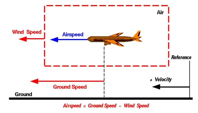
A reference point picked on the ground, the aircraft moves relative to the reference point at the ground at its speed is called ground speed.
AIR SPEED:
Air speed is the difference between ground speed and wind speed. Wind speed is nothing but speed of the wind which will be headwind (opposite to which the airplane strikes) or tailwind ( the wind flows parallel along airplane).
Air speed = Ground speed - Wind speed.
3. Why is it not recommended to use aircraft engine power to move it on the ground at Airport?
SOLUTION:
High engine thrust during maintenance activity can cause considerable damage to airplanes and other elements in the airport environment by throwing debris or weak asphalt road which turn into minor fragments. This is because airflow from the propellors would be around 170km/hr to 400km/hr. Also when taxiing it is very important to look after the precautions so that the high engine thrust activity could not damage any of the nearby planes, elevators, maintenance workers.
Foreign object damage (FOD) caused by high engine thrust can affect airport operations as it relates to
- Airplane structure.
- Flight controls.
- Equipment and personnel.
4. How an aircraft is pushed to runway when its ready to take off?
SOLUTION:
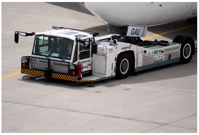
The forward movement of an aircraft, usually with engines off, using the power of a specialised ground vehicle attached to or supporting the nose landing gear. It may occur for the movement of both in service and out of service aircraft. Once the person in charge on the flight deck of the aircraft has given their confirmation of ‘brakes released’ to the person in charge of the ground crew vehicle who are to carry out the tow, the ground crew become responsible for the safe manoeuvring of the aircraft. The ‘traditional’ method of allowing the ground vehicle to move an aircraft is to attach it to the aircraft nose landing gear by means of a towbar. An alternative method which is becoming more common for towing is the use of a specialised vehicle called a ‘towbarless tug’. This positions two low level ‘arms’ either side of the aircraft nose landing gear and these are used to engage with the aircraft gear leg and raise it slightly off the ground.
TAXIING VS TOWING:
It’s important to note that taxiing isn’t the same as towing. When many people hear the word “taxiing,” they envision a ground vehicle physically moving an airplane on the runway. Taxiing, though, specifically involves the use of an airplane’s own propulsion system to move while on the runway. Towing, on the other hand, refers to the use of a ground vehicle. Known as a tug, these ground vehicles connect to airplanes so that they can move and turn airplanes.
5. Learn about take off power, tyre design, rolling resistance, tyre pressure, brake forces when landing.
SOLUTION:
TAKE OFF POWER:
When airplanes are lined up on the runway and cleared for take-off, the pilot will start to advance the thrust levers. On aircraft that are powered by fan engines – especially aeroplanes like the AIRBUS FAMILY where the engines are relatively large – inertia in the big fans at the front may mean that both or all engines do not always ‘spool up’ at the same rate. Until this has happened, the pilot should not advance the throttles any further as to do so could set up an asymmetry that he/she might find difficult to control through nose-wheel steering alone. Once the engines have all ‘spooled up’ it is safe to advance the thrust levers together to the position that will enable the engines to deliver the amount of thrust required for take-off. It is for ‘spool up’ reasons that tower controllers may sometimes observe a hesitation – typically 6 to 10 seconds - after the aeroplane begins to roll forward before its acceleration along the runway appears ‘normal’, and why pilots may not always seem to respond quickly to requests to ‘expedite departure’. The required thrust should be attained before the aeroplane’s indicated air speed passes 80kts. In order to reduce the likelihood of a rejected take-off resulting in an over-run or other undesirable outcome, it is often stated in the SOPs that once above a specified speed during the take-off roll the take-off should only be rejected for specified occurrences. The specified speed is typically 80 knots. Below this speed the take-off may be rejected for any reason. Above the specified speed it is typical for the SOPs to state that the take-off should only be rejected for an engine failure, any type of fire or an unsafe condition that would render the aircraft unable to fly. The call at 80 knots is also used to check that the pilots have not become incapacitated during the take-off roll. If the PM does not make the call, or if the PF does not respond, it could be due to incapacitation and the take-off should be aborted.
TYRE DESIGN:
An aircraft tyre is constructed for the purpose it serves.
- They support the weight of an aircraft while it is on the ground.
- It also provides the necessary traction for braking and stopping of an aeroplane.
- Tyre also helps to absorb the shock of landing and provide cushioning the roughness of takeoff, roll-out, and taxi operations.
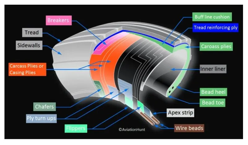
Unlike an automobile or truck tyre, it does not have to carry a load for a long period of continuous operation. However, an aircraft tyre absorbs the high impact loads of landing, and also it’s operating at high speeds for a short time when required. Carcass plies are used to form the tire. They are sometimes called casing plies.
Let’s go through some technical aspects of the tyre.
Retreading – Retreading is methods of restoring a worn tyre by renewing the tread area or by renewing the tread area plus one or both sidewalls. Repairs are included in the tyre retreading process.
Load Rating – Load rating is the maximum permissible load at a specified inflation pressure.
Ply Rating – Ply Rating is used to identify the maximum recommended load rating and inflation pressure for a specified tyre. It is an index of tyre strength.
Speed Rating – The speed rating is the maximum takeoff speed to which the tyre has been tested.
Skid Depth – Skid depth is the distance between the tread surface and the deepest groove as measured in the mould.
Aircraft tyres must have an approved speed and load rating and have sufficient clearance when retracted through landing gear to allow for tyre growth. Tyre growth is the increase in the size of the tyre due to centrifugal forces at high speed.
Airecraft tyre may be with tube or tubeless:
Tubeless tyres are more advantageous over tube-type. There is no longer the use of tube-type tyre in recent aviation. Nowadays all airliners are using tubeless tyres. Tubeless that are meant to be used without a tube has the word TUBELESS on the sidewall of the tyre.
Aircraft tyre may be radial or bias:
Almost all airliners are using Radial tyre. Bias is an older design, and it’s mainly used for road vehicles. Radial tyres have the word RADIAL on the sidewall. Radial tires are more expensive than bias-ply tyres. Radial tires are in demand because of their lower life cycle cost and long term value.
Aviation tyres are conductive:
Aircraft tyres are manufactured with tread rubber with conducting compounds to permit earthing of static charges. In early days when tyres were not sufficiently conductive, aircraft used to have a conductive strip hanging down from the axle of the landing gear. Upon landing, this strip would be the first part of the aircraft to touch the earth. This discharges any static electricity accumulated on the outer surfaces of the aircraft. Now you don’t see them anymore.
ROLLING RESISTANCE:
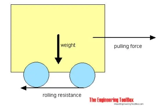
The force that resists the motion of a body rolling on a surface is called rolling resistance or rolling friction.
The rolling resistance can be expressed as `underset(r)(F)=c**W`
c - coefficient of rolling resistance
W - weight of the body
W = `m**underset(g)(a)`
m = mass
`underset(g)(a)`= acceleration due to gravity
Note that the rolling resistance coefficient - c - is influenced by different variables like wheel design, rolling surface, wheel dimensions and tyre pressure.
The rolling resistance can alternatively be expressed as
`underset(r)(F)=underset(l)(c)**W/r`
`underset(l)(c)`=coefficient of rolling resistance (dimensions in length)
r = radius of the wheel
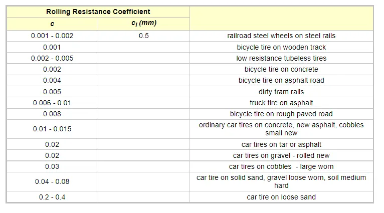
The rolling coefficients for air filled tires on dry roads can be estimated
c = 0.005 + (1 / p) (0.01 + 0.0095 (v / 100)2)
where
c = rolling coefficient
p = tire pressure (bar)
v = velocity (km/h)
TYRE PRESSURE:
A Boeing 777 uses 14 tires, Airbus' A380 carries 22, and the enormous Antonov An-225 demands 32. The key to their remarkable durability is maximizing the air pressure, says Lee Bartholomew, lead test engineer for Michelin Aircraft Tires. The high-flying rubber is typically inflated to 200 psi, roughly six times what you put in an automobile tire, and the tires on an F-16 fighter are pumped to 320 psi. “It's really pressurized air that's so strong,” he says. Aircraft tires are amazing when you think about it. The typical airliner tire can handle a 38-ton load. It can meet the ground 500 times before needing a re-tread, a refresh it can take on seven times in its life. The tires themselves aren't terribly large--- a Boeing 737 rides on 27x7.75 R15 rubber. In English, that means it is 27 inches in diameter, 7.75 inches wide, and wrapped around a 15-inch wheel. The sidewalls aren't terribly thick, and the strength of the tire lies in the cords embedded below the tread, Bartholomew says. They're typically nylon, and more recently a variety known as aramid. Each layer of the casing contributes to its load bearing and air pressure resisting capabilities. Of course, tires can fail, especially when under-inflated or overloaded. Treads can come off and casings can blow out. In the first moments after a plane touches down, the tires are skidding, not rolling. The airplane essentially drags them down the runway until their rotational velocity matches the velocity of the plane. That's why they smoke upon landing, and why Michelin uses grooves instead of the block patterns seen on your car's rubber---blocks would simply break off. (Most tire wear comes from this moment of contact---where the rubber meets the runway.) The stoutest tires are rated for speeds of up to 288 mph. To develop a new sort of tire, or test a tweak, Michelin starts with computer simulation, followed by prototyping. Then it tests how the tires do when they're overloaded or pushed past their speed limit, on simulated takeoffs, landings, and taxiing. Like everything in aviation, tires must meet specific and demanding rules---for example, a tire must withstand four times its rated pressure for at least three seconds.
TPMS (Tire Pressure Monitoring System): Aircraft models have TPMS sensors in their wheels. The system is very similar to the TPMS in automobiles. Cockpit displays show tire pressures for all tires equipped with the sensors.
BRAKE FORCES:
Stopping a 200-tonne aircraft landing at 180 mph requires a lot of braking force. To do this, the 787 has one brake unit on each of the eight wheels on the main gear assembly. On other aircraft types, the brake units are powered by the hydraulics system. An electrical signal is sent from the flight deck to hydraulic actuators near the main landing gear. Here, hydraulic fluid at 3,000 pound per square inch is used to force the brake unit against the wheel, thus slowing it down. This system works fine, but the pipes and actuators that form this part of the hydraulic system come at a considerable weight cost. Extra weight means more fuel burn, which in turn increases costs and carbon emissions.
Designers did away with the use of the hydraulic system and all its associated architecture and instead used electricity to power the brakes. When the pilots press on the brake pedals, an electrical signal is sent to the brake unit on the wheel. Here, electrically powered actuators are used to press the carbon brake disc against the wheel, slowing it down.
By changing to electric brakes, a 787-8 saves 141 pounds per aircraft and a 787-9 saves 245 pounds. The brakes are also known as “plug and play” because electrical wiring replaces the traditional hydraulics and it’s much easier and quicker to change the brake units when needed. Smart features also allow engineers to monitor the brake performance more closely, giving a real-time measurement of wear on the carbon disks.
ELECTRICAL BRAKE:
The brake system on the 787 Dreamliner is controlled by the pilots pressing the tops of the rudder pedals under their feet, demanding the rate of braking which they require. This sends an electric signal to the Left and Right Brake System Control Units (BSCUs).
These then send signals to the four Electronic Brake Actuator Controllers (EBAC) which control the rate of braking on the wheels. Each wheel has four Electric Brake Actuators (EBA), a kind of piston which presses against the carbon brake discs.
The brake disks themselves are made up of two parts. Firstly, there are the rotors. These are connected to the wheel by drive tabs. As these drive tabs are in contact with the inside of the wheel, they spin at the same speed. Depending on the brake manufacturer, there are either four or five of these rotors on each brake assembly.
The second part of the disks are the stators. These sit around each rotor and are fixed in place and thus don’t move. As the wheel turns, the rotors spin round inside the stators. When the brakes are applied, the four EBAs apply pressure to the first stator. This in turn squeezes the stationary stators up against the spinning rotors and it’s this friction which slows the wheel down.
ANTI-SKID PROTECTION:
When landing on slippery runways, there’s a chance that the wheels may start to skid as the brakes are applied. To stop this from happening and to maintain maximum effective braking, each wheel has anti-skid protection.
Using a variety of sources to determine the aircraft speed, the brake units know how fast the wheels should be spinning. If that speed drops significantly, it’s because the current brake pressure on that wheel is too great and the wheel is just skidding over the surface.
In this situation, the anti-skid system automatically reduces the braking on that wheel to a point where the skid stops before reapplying the pressure. All this is done in a fraction of a second.
AUTOBRAKE:
Pressing on the brakes is pretty straight forward when taxiing in a straight line at low speed. However, when we’re landing in strong winds, it can be a little tricky. We need to use our feet on the rudder pedals to line the nose of the aircraft up with the runway centerline at the last moment. Then, whilst holding that position, slide our feet up to press the toe brakes. Really not very easy when moving at 160 mph.
To help us get the braking underway as soon as we touch down, we have the autobrake system.This provides automatic braking at a preselected rate as soon as the aircraft senses that it is on the ground. It also provides full braking pressure in the case of a rejected takeoff if the speed is above 85 knots (98 mph).
In addition to the brakes, there are two other systems which help slow the aircraft down on landing. The spoilers and the reverse thrust.
SPOILERS:
Have you noticed the large panels on the top of the wings raise up on touch down? These are the called the spoilers as they literally spoil the airflow over the wing. This dumps any remaining lift the wings are generating, allowing the wheels to take all the weight and achieve maximum efficiency from the brakes.
REVERSE THRUST:
The final part of the braking process comes from reverse thrust. Just after we have touched down, we pull two levers on top of the thrust levers to engage the reverse thrust, a sort of “reverse gear” for jet engines. This causes blockers inside the engine to deploy and a door in the side of the engine to slide backward. The air which normally leaves the engine out the back is deflected forward by the blockers and out through the door. There are two stages of reverse thrust — idle reverse and max reverse. Idle reverse is used on most landings and max reverse is used when the landing performance requires it, normally when the aircraft is landing at hot or high elevation airfields. This forward directed airflow helps slow the aircraft down but is most efficient at high speeds. If using max reverse, we drop this down to idle reverse at 60 knots (70 mph) and then back to normal thrust as we vacate the runway at around 20 knots (25 mph).
6. A. With necessary assumptions, calculate the force and power required to push / pull an aircraft by a towing vehicle.
SOLUTION:
Total weight of airbus A350 = 248000kg
g=9.81 m/sec^2
co-efficient of rolling resistance Cr1 = 0.006
Drag co-efficient Cd1 = 0.5
Air densiity(`rho`) = 1.125 kg/m^3
Frontal area(A) = 150 m^2.
Velocity(V) = 7m/s
Total weight of the towing vehicle (challenger 280) = 24000Kg
Drag force and rolling resistance force of the towing vehicle is much less compared to the airbus A350. So we are neglecting them.
Rolling resistance force (Fr) = Cr1*m*g =0.006*248000*9.81=14.59KN
Drag force(Fd) = 0.5*`rho`*Cd1*A*V^2 = 0.5*1.125*0.5*150*7^2 = 2.06KN
Total resistive force(Ft) = Fr+Fd = 16.65 KN
Power required for a towing vehicle = Ft * V = 16.65 * 7 = 116.55 Kw.
B. Develop the model for the calculated force and power using Simulink.
SOLUTION:
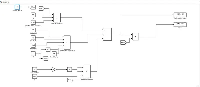
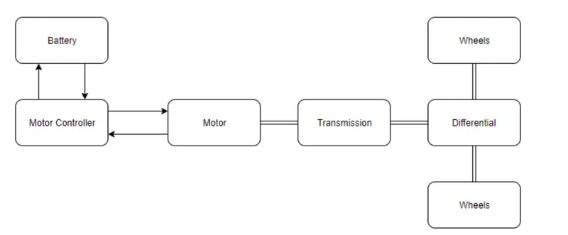
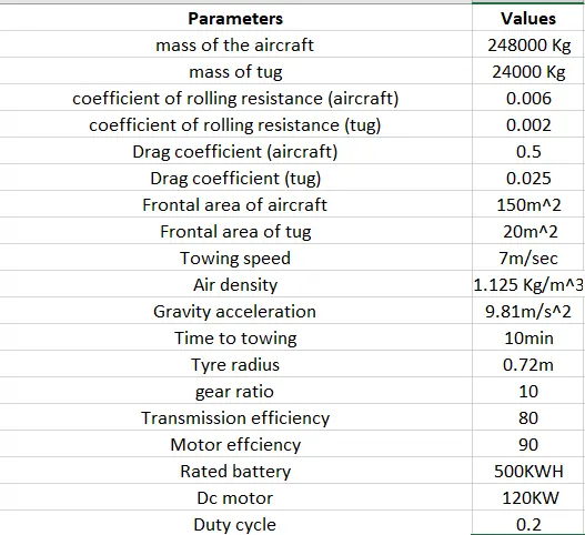
7. A. Design an electric powertrain with type of motor, it’s power rating, and energy requirement to fulfill aircraft towing application in Simulink. Estimate the duty cycle range to control the aircraft speed from zero to highest. Make all required assumptions. Prepare a table of assumed parameters. Draw a block diagram of powertrain.
SOLUTION:
Power required for a towing vehicle to tug a airbus A350 = 116.55 KW.
Total resistive force = 16.65 KN.
Assumption:
Tyre radius of towing vehicle = 0.762m
Torque required at the wheels = total force * radius = 16.65*0.762 = 12.68KNm
we assume gear ratio to 10 and transmission efficiency(Teff) is 80%, motor efficiency(Meff) is 90%
Motor torque = (wheel torque)/(gear ratio*Teff*Meff) = (12.68)/(10*0.8*0.9)= 1.76 KNm
Assuming 500kWh baterry
Total energy consumed = 116.55*0.1667 = 19.42KWh ( that is for 10 min)
Duty cycle = required power/rated power = 116.55/500 = 0.2.
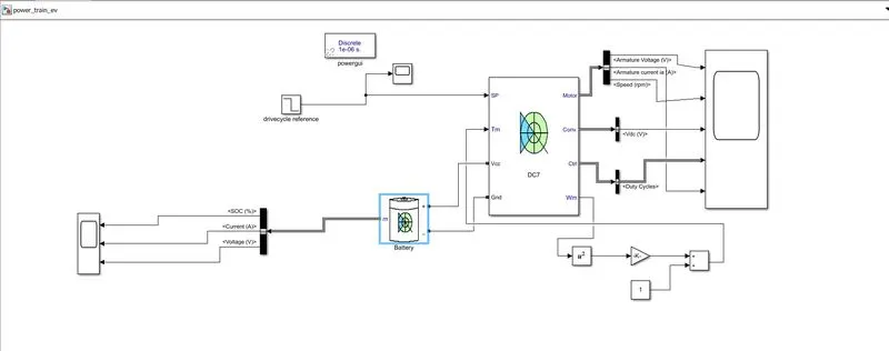
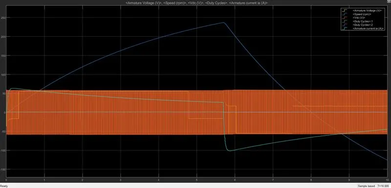
Blockdiagram of Powertrain:
B. Also, Design the parameters in excel sheet.
LINK1:
https://drive.google.com/file/d/1pf9pmMXv2yTReBw3mXoWKpBeE0JZ_VIH/view?usp=sharing
LINK2:
https://drive.google.com/file/d/1LrgkrFrPDc0b49DFaz9_BJrIP4d8JMpL/view?usp=sharing
LINK3: