Project 1 (Mini Project on Vehicle Direction Detection
Vehicle Direction Detection
AIM:
- Development of MATLAB Simulink model as per requirement.
- Tag the requirements to the simulink model; tagging requirement 1 & requirement 2 to their corresponding subsystems is fine.
- MBD compliant changes, Data Dictionary creation & code generation is added advantage, and that is not scope of this project.
- If choosing code generation, Storage class for Input signals: ImportedExtern; Storage class for Output signal: Export to File; Storage class for local signals: localizable; Storage class for calibration signals: Const.
- Choose sample time for all signals as 0.01.
Development of MATLAB Simulink model as per requirement:
Requirement - 1:
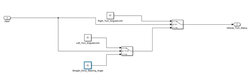
- Steering wheel input as yaw rate (Signal name: SteeringWheel_YawDegreeInput) is the input for this system.
- This is compared against 3 angular values, one each for left turn, right turn & straight drive (Calibration Values: Right_Turn_AngularLimit, Left_Turn_AngularLimit, Straight_Drive_Steering_Angle) to say which specific direction the steering wheel is turning towards.
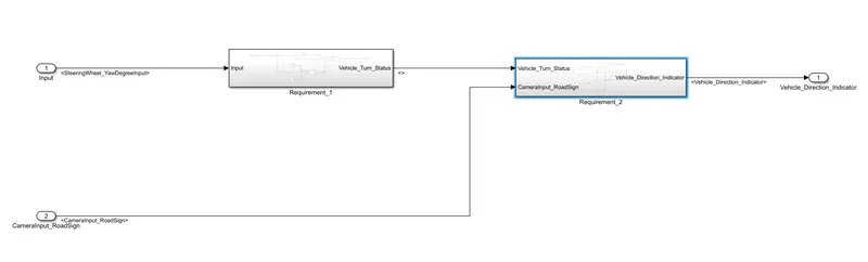
- Use switch blocks to compare & develop this requirement. Keep this requirement in a subsystem & output of this requirement is a local signal (Signal Name: Vehicle_Turn_Status).
Requirement – 2:
- Keep this requirement as a separate subsystem. Inputs to this requirement are local signal from requirement 1 (Signal Name: Vehicle_Turn_Status) & an input signal from camera (Signal Name: CameraInput_RoadSign), which confirms the occurrence of a road sign.
- Signal Vehicle_Turn_Status is compared against calibration values (Calibration Values: RightTurn_RoadSign, LeftTurn_RoadSign, Straight_RoadSign), if each of them is found equal, then each of the three corresponding output is compared against the camera input signal,
- Using a logical operator block, only one among them is finally given as output signal (Signal Name: Vehicle_Direction_Indicator).
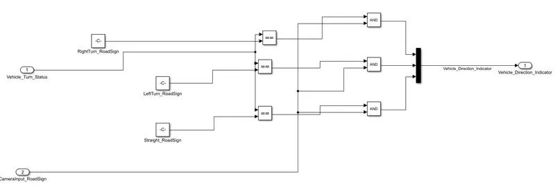
Both the requirements are created and created subsystems for each
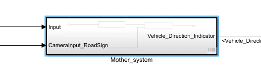
Then these subsystems are created as a single subsystem
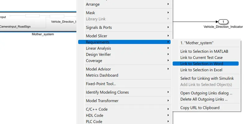
Requirement tagging is done by right clicking on the subsystem and linking to word document, where we could find more information of the working system.
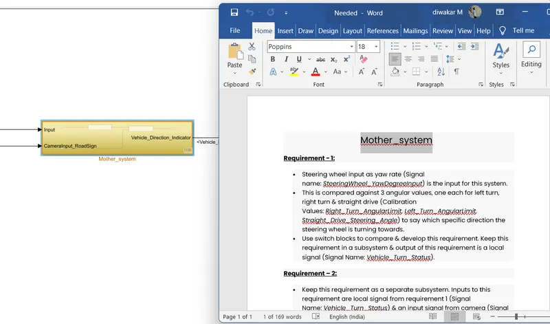
By clicking Mothr_system, word document opens
Data dictionary is created based on the given requirement.
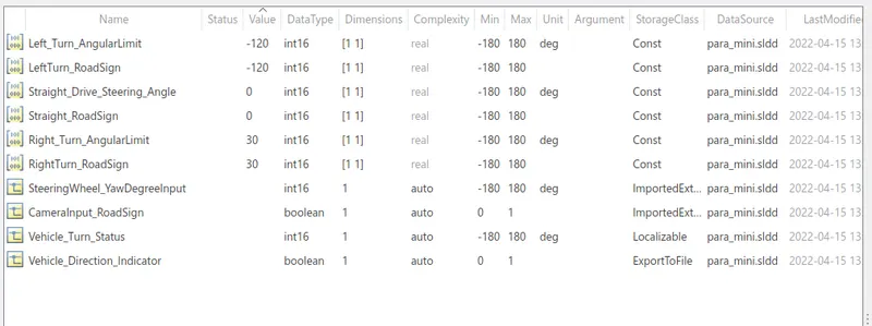
Storage class for Input signals: ImportedExtern; Storage class for Output signal: Export to File; Storage class for local signals: localizable; Storage class for calibration signals: Const are created. Sample time for all signals as 0.01 are choosed.
Solver setting is changed

And also code generation is changed-embedded coder is selected
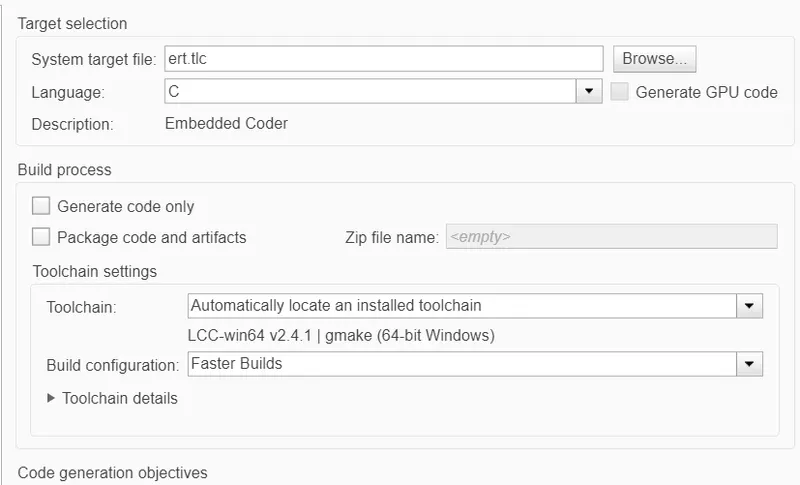
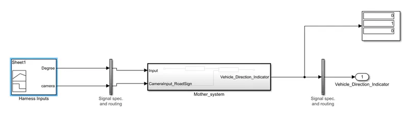
Model created is runned at Model in loop for testing it in number of cases.
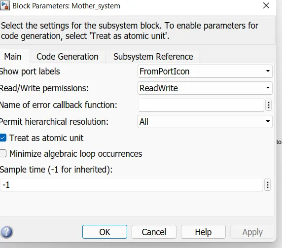
making the subsystem as a atomic unit.
Creating Test Harness for the subsystem
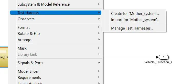
Choosing signal builder to import the test cases
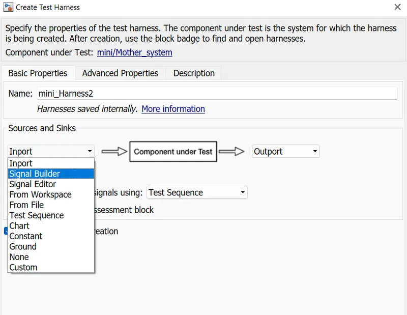
Making it to a Model in loop
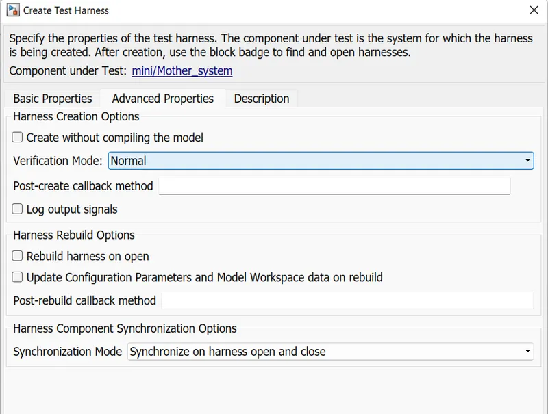
Test Harness model is created

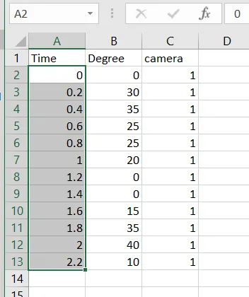
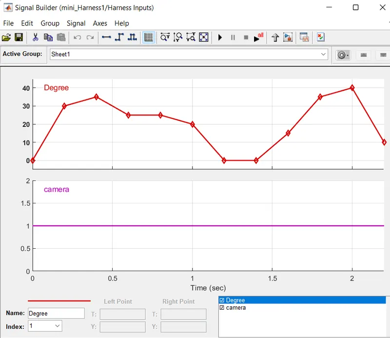
Xcel file is imported in signal builder
RESULT:
Simulation is done for the following test cases and the vehicle direction indicator shows the left, right or straight.
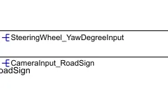
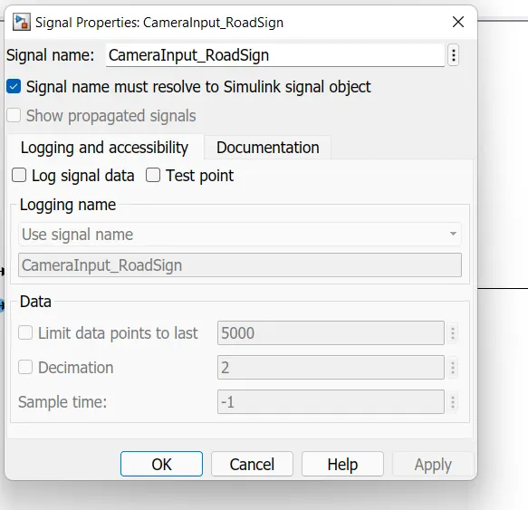
Signal resolving is done by right clicking on the signals and selecting the properties. Propagating signals is done by clicking 'show propagated signals'
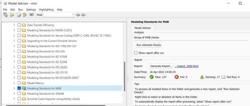
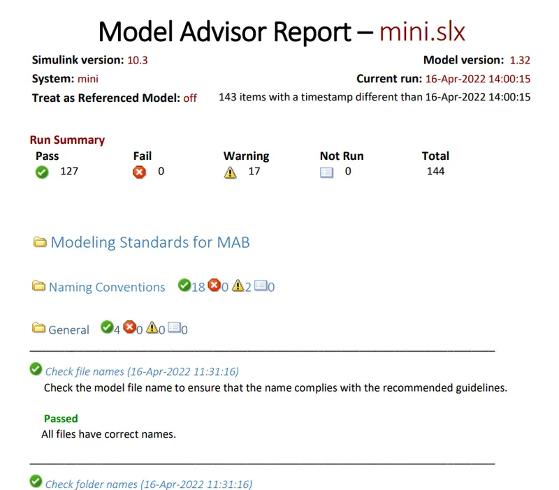
MODEL ADVISOR:
Warnings are reduced from 26 to 17 and generated a report on it which will be submitted below.