Final Project: Design of an Electric Vehicle
Qn 1.) Create a MATLAB model of electric car which uses a battery and a DC motor. Choose suitable blocks from Powertrain block set. Prepare a report about your model including following:
Electric cars are predicted to be the next disruptive market force for transportation and technology. They have the potential to revolutionize how energy is used, created and redirected. Electric cars are one solution to the negative environmental impact of conventional cars. However, they have also proven to have many more benefits to society. The advent of electric cars has called for an improvement in overall energy usage and generation. They have shown how important it is to find alternate sources of fuel and they can positively affect the environment and society as a whole.
To simulate an electric vehicle, we need to understand the topology or the block diagram of the electric vehicle at the first hand. The block diagram for an electric vehicle simulation is as follows:
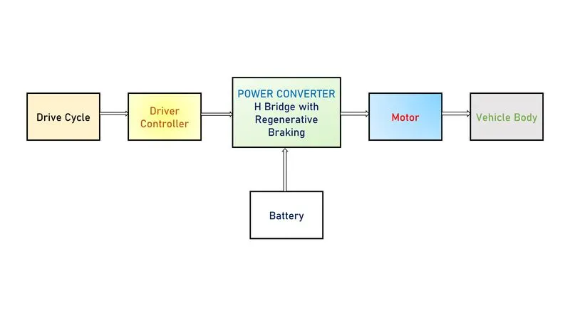
Vehicle Body: Vehicle body is simply the frame of the vehicle which includes components such as wheels, chassis, transmission system, axles etc. Simulink readily has a "Vehicle body" block under simscape library where we can feed parameters such as mass of the vehicle, Drag , Pitch etc. The actual vehicle body also includes wheels which is also available in the simscape library as "Tires(Magic Formula)". Other than these components, we can also include simple gear block to simulate the transmission system.
Motor: The motor in the electric vehicle is the machine that converts the electrical energy from the battery into mechanical energy so that we could drive the wheels. There are different motors used in the actual EVs namely induction motor, BLDC motor, Internal Permanent Magnet Synchronous Reactance Motor etc. In our simulink model, for the sake of simplicity, we use DC Motor for simulation.
Battery: Like the petrol or diesel in the IC engine vehicles, the source of fuel for the electric vehicle is the battery. A battery pack in a EV will consist of many individual cells of lower voltages stacked together in series connection to get a larger net voltage battery pack. Many of the EV manufactures like Tesla, Nissan , Audi etc use Lithium Ion batteries in their vehicles. This battery supplies a constant DC voltage and it is connected with a motor controller.
Power Converter: Power converter can be regarded as the brain or processing unit of an electric vehicle. It basically consists of power electronic devices. It is the one which enables the control of an Electric vehicle. Because, the voltage from the battery is a constant DC and if it is given directly to the motor (say BLDC), the motor would always run at constant speed and we could NOT achieve the speed control of the motor. This problem is solved by the power converter which consists of inverter or chopper configurations according to the motor used and it employs various techniques such as Vector Field control, PWM etc to control the speed of the motor.
Drive Cycle and Driver Controller: These blocks are specific to the simulation purposes as they act as the reference for the simulation of the model. The drive cycle is simply a velocity vs time plot and this is fed to a driver controller which takes in the input speed and the current output speed and compares both the speeds to get the error. This error is then rectified by doing acceleration or braking inorder to satisfy the reference drive cycle.
Simulation of Audi-Etron using Simulink:
In this project, we are trying to simulate a electric vehicle by feeding the actual parameters of Audi-Etron 50 Quattro from the official data sheet.
The simulink model is as given below:
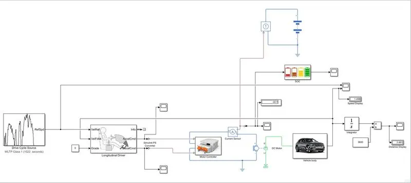
The overall structure of the model resembles with the block diagram as discussed above. The subsystems in the simulink model are:
1.) Motor Controller
2.) Vehicle Body
3.) State of Charge Subsystem (SOC)
Vehicle Body Subsystem:
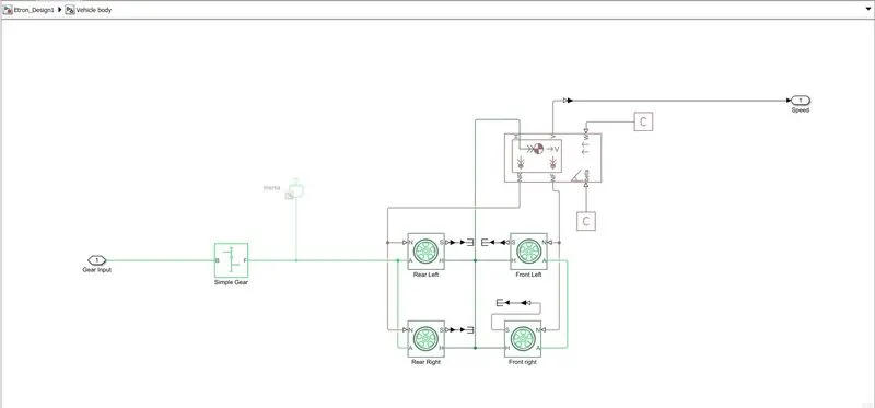
The vehicle body subsystem consists of "Vehicle body" block, "Tires(Magic Formula)" blocks and a "Simple Gear" block from the simscape library. The tires are connected to a common hub from the vehicle body and the axles are connected within the front tires and the rear tires. The normal forward force and the normal reverse force are given to the front and rear tires respectively. The wind velocity and the angle of inclination of the vehicle are given with the help of physical constants. A simple gear block here simulates the tranmission system of the vehicle in a simple way.
Datasheet of Audi-Etron:
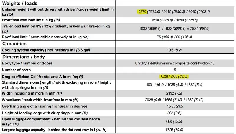

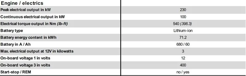
From the datasheet, the values are fed into the simulink blocks.
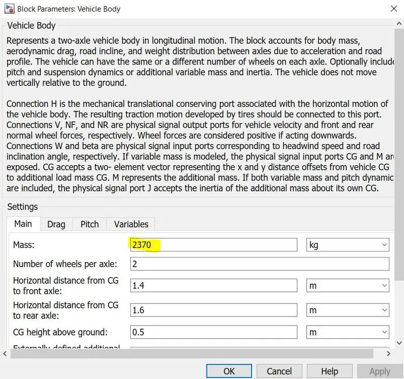
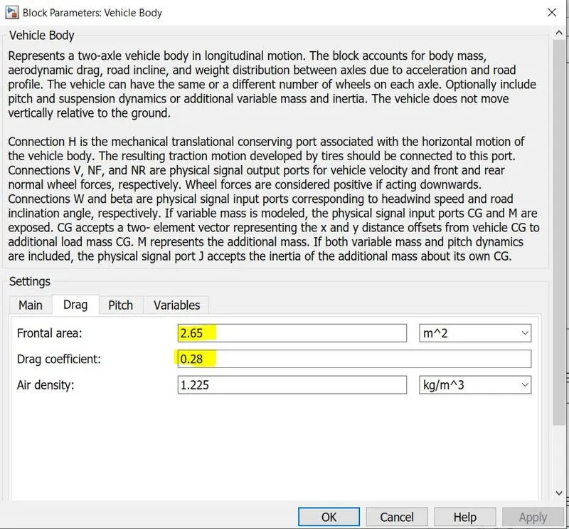
The specifications of the tires are taken from the data sheet and the "Rolling radius" is calculated using the tyre formula.
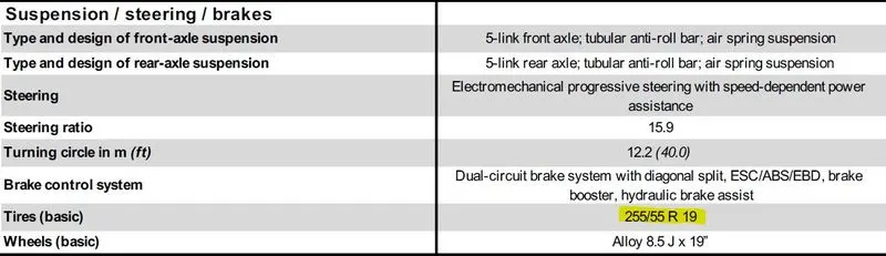
Here, Diameter of the rim= 19 inches= 0.4826 m
Side Wall height= 55% of 255 mm = 0.14 m
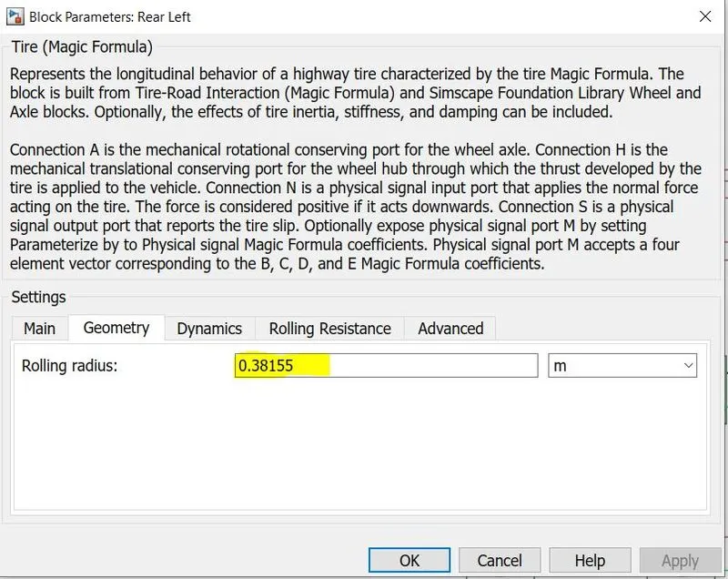
Rolling Radius of the of tires = radius of the rim + Side wall height = (0.4826/2)+0.14= 0.38155 m
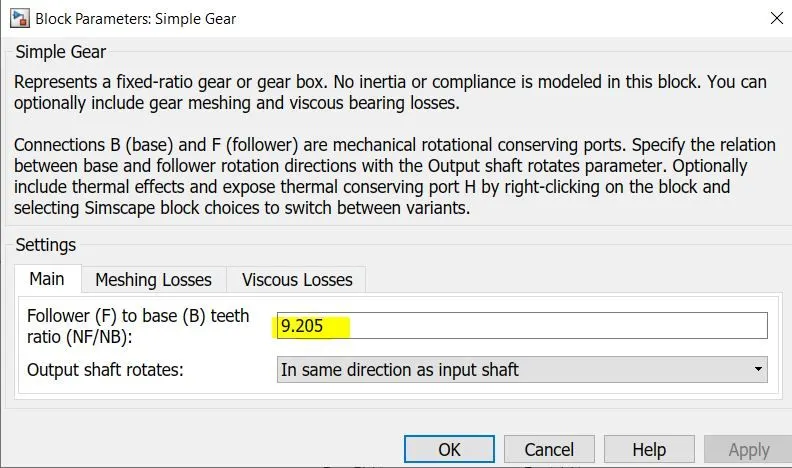
This calculated radius is fed as the rolling radius parameter. Also the simple gear ratio is given as 9.205 as given in the data sheet.
The wind velocity and the vehicle inclination are given as 0 for the sake of simplicity.
Motor Controller Subsystem:
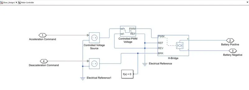
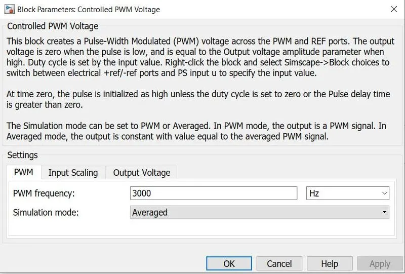
The motor controller subsystem consists of blocks such as "Controlled Voltage Source", "Controlled PWM Voltage", "H-Bridge" and a solver configuration. Here, the accleration and the deacceleration command are received from the logitudinal driver block and Pulses of variable width are produced by the "Controlled PWM voltage" block are fed into the H bridge. The H-bridge then gives a voltage to the battery corresponding to the pulse. This variable voltage across the battery inturn controls the speed of the DC motor.
The block parameters are given below:
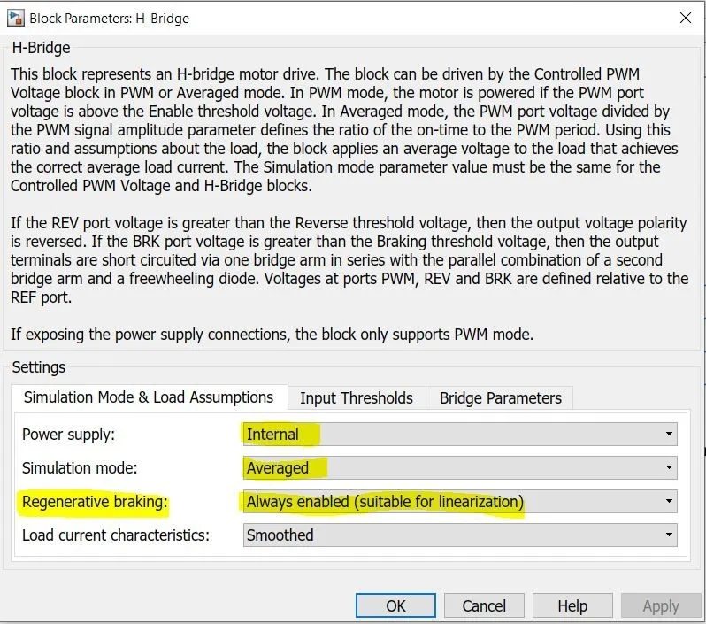
Important Note: The regenerative braking option in the H bridge block should always be enabled in order to ensure the energy feedback to battery and also to comply the vehicle inaccordance with the drive cycle.
H bridge Converter
An H-bridge is an electronic circuit that switches the polarity of a voltage applied to a load. Most DC-to-AC converters (power inverters), most AC/AC converters, the DC-to-DC push–pull converter, isolated DC-to-DC converter, most motor controllers, and many other kinds of power electronics use H bridges.
The term H-bridge is derived from the typical graphical representation of such a circuit. An H-bridge is built with four switches (solid-state or mechanical). When the switches S1 and S4 (according to the first figure) are closed (and S2 and S3 are open) a positive voltage is applied across the motor. By opening S1 and S4 switches and closing S2 and S3 switches, this voltage is reversed, allowing reverse operation of the motor.
Using the nomenclature above, the switches S1 and S2 should never be closed at the same time, as this would cause a short circuit on the input voltage source. The same applies to the switches S3 and S4. This condition is known as shoot-through.
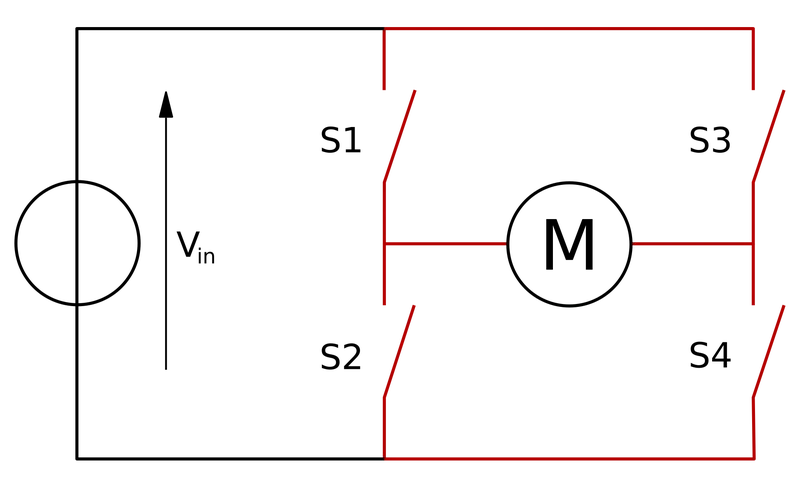
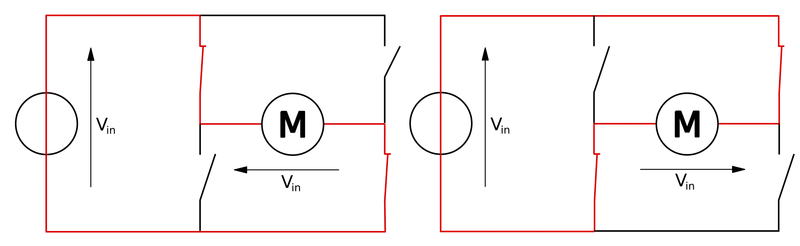
The above two diagrams shows the structure of the H-Bridge and the two basic states of an H-Bridge.
SOC Subsystem:
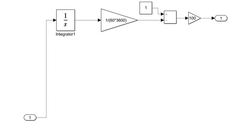
The SOC subsystem is employed to obtain the percentage drain in the battery of the simulated vehicle.
DC Motor:
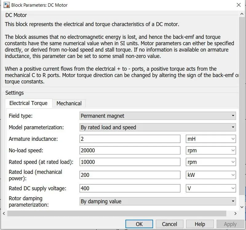
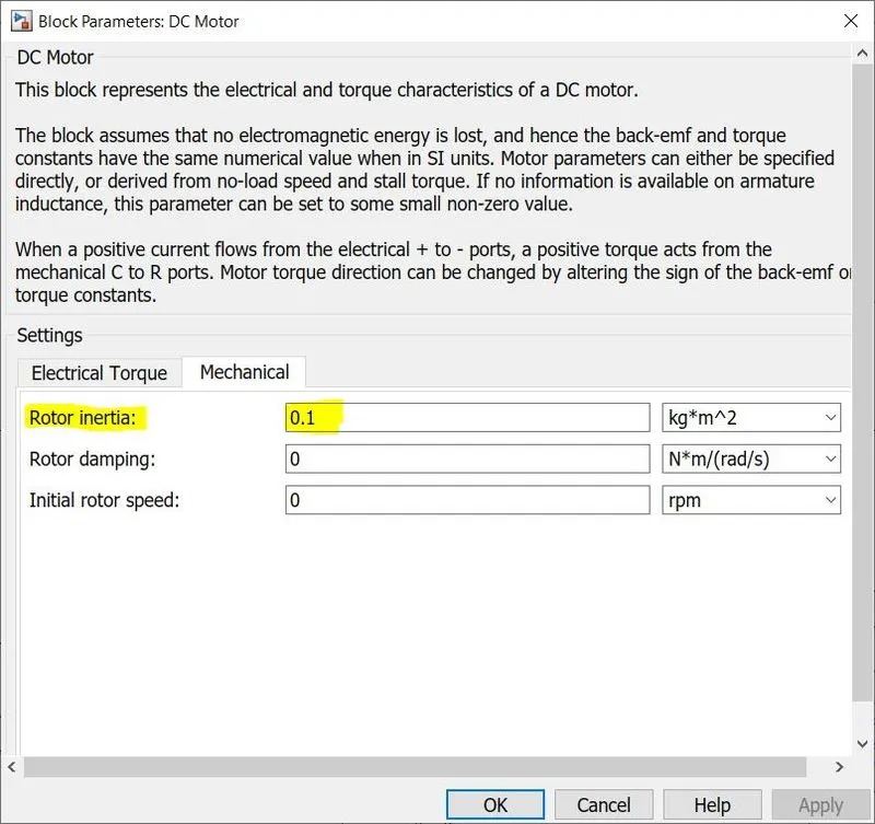
In this model, a DC motor is used for simplicity whereas in real case of Audi Etron 50 quattro, an AC Induction/Asynchronous motor is used. Due to this fact, developing the DC motor parameters for this simulink model was purely done by trail and error method so that the vehicle could match with the driving cycle. It would be a quite difficult to find such DC motors in real world with good efficiency. But, for the sake of simulation, it is used. The DC motor block parameters are as follows:
Datasheet for Engine and electrics is as follows:
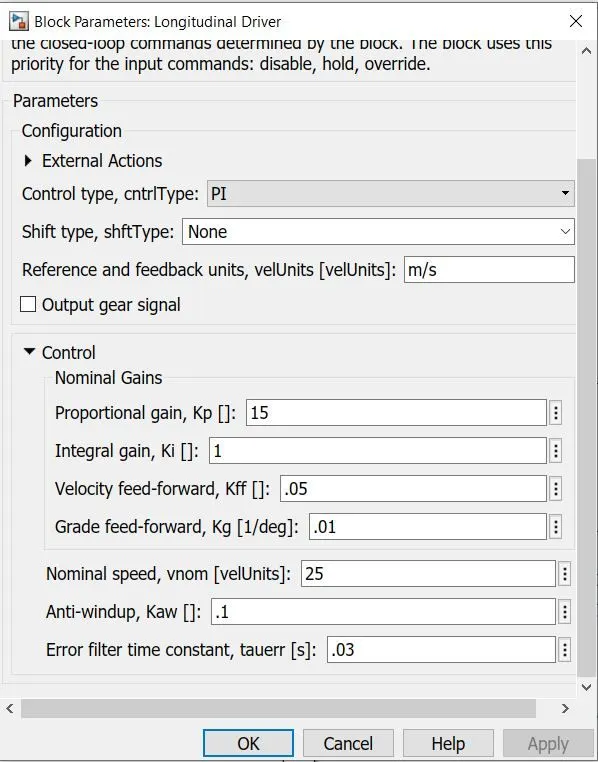
Longitudinal Driver:
It is a parametric longitudinal speed tracking controller for generating normalized acceleration and braking commands based on reference and feedback velocities. From the simulink model, we could see that the vehicle output speed is fedback and compared with the reference speed (drive cycle) inorder to obtain the acceleration command and the deacceleration command. The block parameters are left default as given below
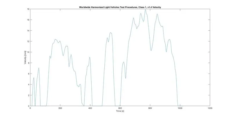
Drive Cycle:
Drive cycle is simply a speed vs time graph. It is generally used for various vehicle testings and simulations. The drive cycle used in this simulation is the WLTP Class 1 drive cycle which is having data for 1022 seconds.
Results
1.) Vehicle Speed:
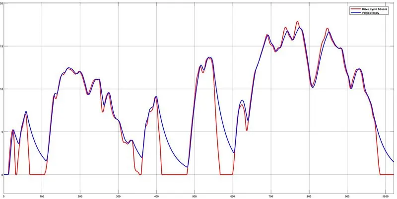
Thus, we could see that the vehicle speed almost matches with the drive cycle. There is some deviation during braking instances. That could be accounted for not using the actual motor as used used in the vehicle. Also, for the given mass of the vehicle (2370 kg), the inertia would be very high for the vehicle to slow down suddenly with this DC motor.
Distance Travelled:
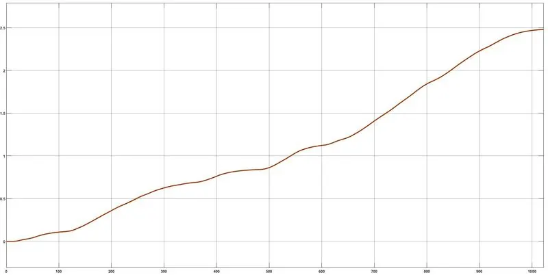
Hence for the given period of time, the vehicle could almost travel a distance of 2.5 Kms.
State of Charge(SOC):
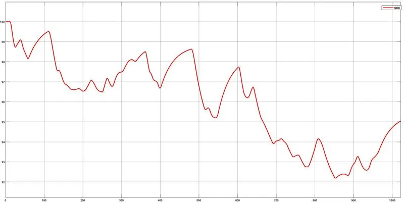
Thus, almost 95% of battery remains at the end of the driving cycle. This is mainly due to the regenerative braking feature.
Conclusion:
Thus, an Electric vehicle model is created using simulink and the parameters are fed close to real values of a AUDI Etron Quattro. The speed of the vehicle has few variations with the drive cycle which could be accounted for the motor used in this simulation (i.e DC motor). A perfect result could be achieved if we could simulate the model with exact motor used.