Final Project: Design of an Electric Vehicle
Create a MATLAB model of electric car which uses a battery and a DC motor. Choose suitable blocks from Powertrain block set. Prepare a report about your model including following:
WHAT IS AN ELECTRIC VEHICLE (EV)?
lectric vehicles have low running costs as they have less moving parts for maintaining and also very environmentally friendly as they use little or no fossil fuels (petrol or diesel). While some EVs used lead acid or nickel metal hydride batteries, the standard for modern battery electric vehicles is now considered to be lithium ion batteries as they have a greater longevity and are excellent at retaining energy, with a self discharge rate of just 5% per month. Despite this improved efficiency, there are still challenges with these batteries as they can experience thermal runaway, which have, for example, caused fires or explosions in the Tesla model S, although efforts have been made to improve the safety of these batteries.
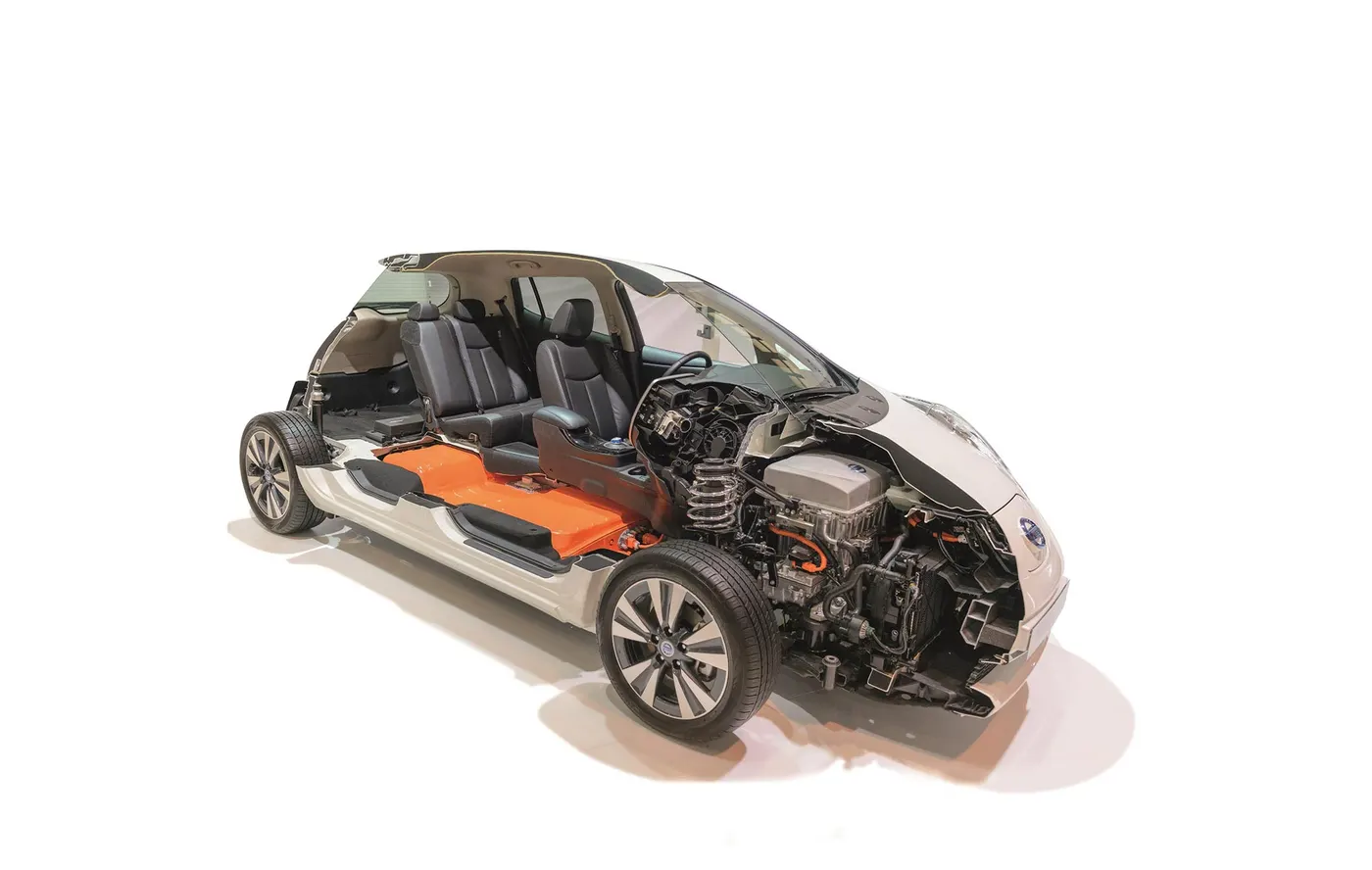
There are two main types of electric vehicles (EV); fully electric and plug-in hybrids:
Battery Electric Vehicles (BEV)
Compared to an internal combustion engine, battery powered electric vehicles have approximately 99% fewer moving parts that need maintenance.
Advantages of a BEV:
- Creates very little noise
- No exhaust, spark plugs, clutch or gears
- Doesn't burn fossil fuels, instead uses rechargeable batteries
BEVs can be charged at home overnight, providing enough range for average journeys. However, longer journeys or those that require a lot of hill climbs may mean that the fuel cells require charging before you reach your destination, although regenerative braking or driving downhill can help mitigate against this by charging the battery packs.
The typical charging time can range from 30 minutes and up to more than 12 hours. This all depends on the speed of the charging station and the size of the battery.
In the real world, range is one of the biggest concerns for electric vehicles, but is something that is being addressed by industry.
Plug-in Hybrid Electric Vehicles (PHEV)
Rather than relying solely on an electric motor, hybrid electric vehicles offer a mixture of battery and petrol (or diesel) power. This makes them better for travelling long distances as you can switch to traditional fuels rather than having to find charge points to top up the battery.
Of course, the same disadvantages that apply to combustion engine vehicles also apply to PHEVs, such as the need for more maintenance, engine noise, emissions and the cost of petrol. PHEVs also have smaller battery packs, which means a reduced range.
The main components of an electric vehicle are:
- Battery (auxiliary)
- Electric traction motor
- Onboard charger
- Thermal system (cooling)
- Power electronics controller
- DC/DC converter
- Charge port
- Transmission (electric)
- Traction battery pack
BATTERY (AUXILIARY)
The auxiliary battery of the electric vehicle provides electricity to power the accessories of the vehicle.
ELECTRIC TRACTION MOTOR
Power is taken from the traction battery pack and with this the motor drives the wheels of the vehicle. Some vehicles use motors which serve as drive as well as regeneration.
ONBOARD CHARGER
AC electricity supplied via the charge port is converted to DC power for charging the traction battery. It also communicates with the charging equipment and monitors battery characteristics such as voltage, current, temperature and state of charge while charging the pack.
THERMAL SYSTEM (COOLING)
The thermal system for cooling makes sure that proper operating temperature range of the engine, power electronics, electric motor and other components are maintained
POWER ELECTRONICS CONTROLLER
The flow of electricity which is delivered by the traction battery to the electric motor is controlled and the required speed and torque is produced.
DC/DC CONVERTER
The high voltage of the traction battery is stepped down to a low voltage DC power to run the vehicle accessories and recharge the auxiliary battery.
CHARGE PORT
The charge port is an external power supply from which the traction battery in the electric vehicle is charged.
TRANSMISSION (ELECTRIC)
The transmission converts electric power to mechanical power in order to drive the wheels of the vehicle
TRACTION BATTERY PACK
The traction battery pack stores electricity for use by the electric traction motor.
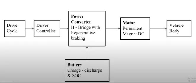
(1) Battery : The battery of an electric car can be charged through the use of ordinary grid electricity at a specialized power station. But aside from the conventional lithium-ion battery technologies, there are also other major battery technologies which can be used for electric cars.
(2) Motor Controller : The motor controller of an electric car administers its complete operation and the distribution of its power at any given moment. It acts as a floodgate between the motor and batteries. It helps monitor and regulates all key performance indications such as the vehicle’s operator, motor, battery, and accelerator pedal. It has a microprocessor which can limit or redirect current. It is used to either improve the mechanical performance of the car or suit the operator’s driving style. There are also more refined controllers which are capable of greater accuracy and thus, higher efficiency.
(3) Electric Motor : Unlike a gasoline engine with lots of moving parts, a motor only has one moving part. This makes it a very reliable source of motive power. Choosing an electric motor depends on the car’s system voltage. They can be structured to use either AC or DC current. AC motors are less expensive and lighter compared to DC motors. They are also more common and they tend to suffer from less mechanical wear and tear. However, AC technology requires a more refined or sophisticated motor controller.
Main System
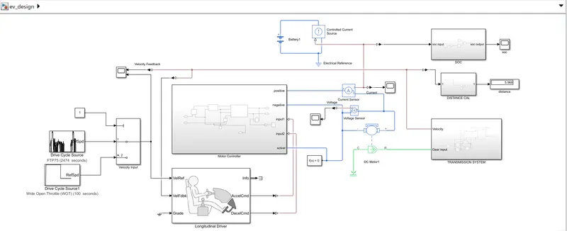
So, in this section, we will see the whole creation of the above model step by step. The model shown above has four subsystems. So, first, we'll go through each subsystem and examine what components are included, along with a detailed explanation of how each component works.
In here we can first see about the motor controller subsystem so,
Motor controller subsystem
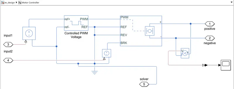
The H-bridge is used due to the four inputs from PWM generators,REV,REF and braking. And another terminal is connected from motor, a voltage sensor is attached to it due to conversion of electrical signal to physical. On the other hand PWM controlled voltage control is used for input to H-bridge.
Hence, in this subsystem we constructed the control system of our vehicle, where the two inputs are coming from longitudnal driver which commands control and both the components operate accordingly.
This subsystem contains H-bridge and controlled PWM voltage block we can see what these blocks are for
H-bridge block
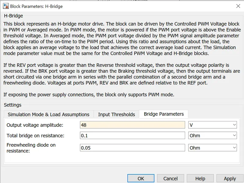
The H-Bridge block represents an H-bridge motor driver. The block has the following two Simulation mode options: PWM — The H-Bridge block output is a controlled voltage that depends on the input signal at the PWM port.
An H-bridge motor drive is represented by this block. The Controlled PWM Voltage block can drive the block in PWM or Averaged mode. If the PWM port voltage is greater than the Enable threshold voltage, the motor is operated in PWM mode. In Averaged mode, the ratio of the on-time to the PWM period is defined by the PWM port voltage divided by the PWM signal amplitude parameter.The block delivers an average voltage to the load that produces the right average load current using this ratio and assumptions about the load. The Simulation mode parameter value for the Controlled PWM Voltage and H-Bridge blocks must be the same. In layman's terms, it's a set of four switches. And the information entered is as follows.
Controlled PWM Voltage
Many industrial applications use pulse width modulation (PWM) signals because such signals are robust in the presence of noise. When using Simulink Control Design software, subsystems that contain PWM signals do not linearize well due to discontinuities in the signal.
This block generates a PWM voltage across the PWM and REF ports. When the pulse is low, the output voltage is zero, and when it is high, it equals the Output voltage amplitude parameter. The duty cycle is determined by the input value.
Transmission system block
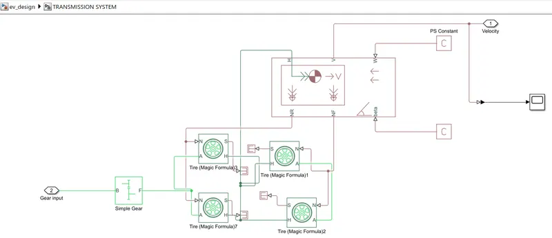
Here, we first place the tyres, which will be powered by the motor via the gear and vehicle body. Then we set up the vehicle body, which will represent all of the weights and connect the tyres, and we open an input for velocity, which will come later from the driving cycle. Then we added a simple gear that will assist in moving the car with the help of the tyres. It also has an input that will come from the motor's shaft.
The above subsystem is the base of the model as, it contains:
Tires: We're designing a four-wheeled EV, therefore we'll need four of these tyres, with H representing the hub, S representing tyre slip, N representing normal force, and A representing axle connection.
Vehicle Body: The Vehicle Body block represents a two-axle vehicle body in longitudinal motion. The vehicle can have the same or a different number of wheels on each axle. ... The block accounts for body mass, aerodynamic drag, road incline, and weight distribution between axles due to acceleration and road profile.
Simple Gear:The gear ratio between the follower (F) and base (B) is 2:1. ... Thus the angular velocity of the follower shaft is half the angular velocity of the base shaft. The follower shaft torque is twice the base shaft torque. An alternative to adding sensors to your model is to use Simscape data logging.
SOC BLOCK
SoC Blockset provides Simulink blocks and visualization tools for modeling, simulating, and analyzing hardware and software architectures for ASICs, FPGAs, and systems on a chip (SoC).
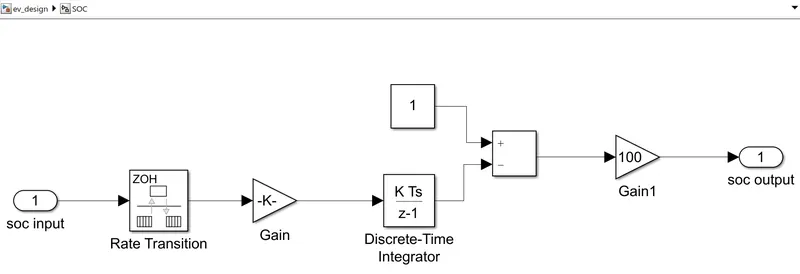
It is the subsystem that has been designed to monitor the battery disipation of the vehicle while it is running and display the percentage of battery remaining. It includes a rate transition and a discrete time integrator, which convert and aid in signal exchange.
Distance calculator
It is used to calculate the distance of vehicle travelled
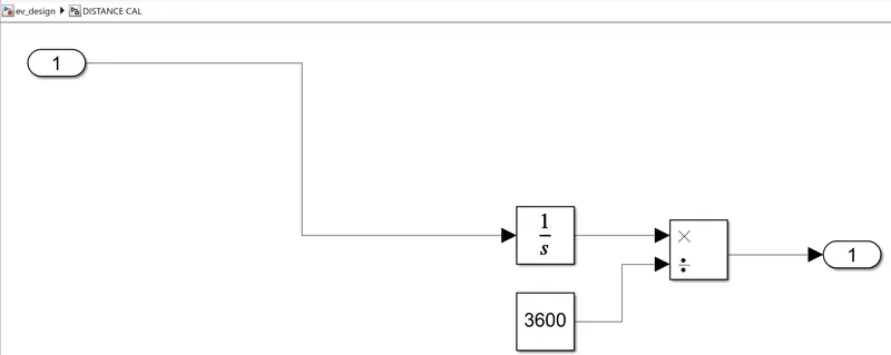
This subsystem is designed as a display to show the vehicle's distance travelled. It has an intergrator, which aids in calculating the distance in kilometres when the 3600 constant is multiplied by it.
In here we are taking simple dc motor so we have to check the configuration of that block parameter
Dc Motor
The DC Motor block represents the electrical and torque characteristics of a DC motor using the following equivalent circuit model: You specify the equivalent circuit parameters for this model when you set the Model parameterization parameter to By equivalent circuit parameters
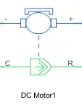
Because the block assumes no electromagnetic energy is lost, the back-emf and torque constants have the same numerical value when expressed in SI units. Motor specifications can be supplied explicitly or calculated from no-load speed and stall torque. If no information on armature inductance is available, this parameter can be set to a tiny non-zero value.
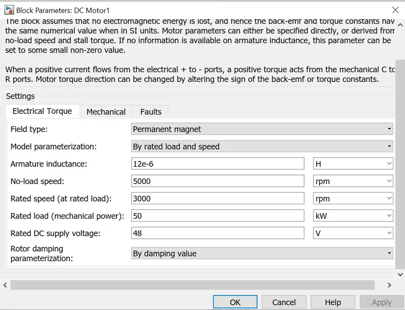
A positive torque acts from the mechanical C to R ports when a positive current flows from the electrical + to - ports. The sign of the back-emf or torque constants can be adjusted to vary the direction of the motor torque.It receives the input command from the motor controller and sends it to the transmission system. And when the car brakes, it acts as a generator, charging the battery at that time owing to regenrative braking.
BATTERY
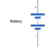
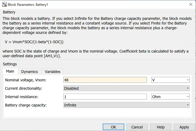
Lets come to battery part, we will be using a simple battery which will be charged from outside means but in this case we will be using a simple battery for quick simulation, with following parameters
Longitudinal Driver :
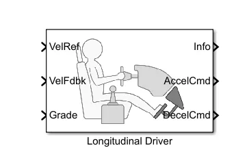
The powertrain blockset includes a built-in block called Longitudinal Driver.
The VelRef port is a reference velocity port that receives input drive cycle data. The feedback velocity is represented by the VelFdbk port. The vehicle body's real velocity output is connected here. When the real (feedback) velocity is compared to the reference velocity,
The driver block generates accelerating and braking signals to minimise the error between the two velocities in question.
The grade angle correlates to the grade. In this scenario, the grade is zero. AccelCmd and DecelCmd correspond to the acceleration and deceleration commands generated, respectively, and are connected to the Controlled PWM Voltage block's corresponding ports.
VELOCITY INPUT:
It is the multi-port input that passes through the input signals corresponding to the first input's shortened value. From top to bottom, the inputs are numbered (or left to right). The control port is the first input port. The remaining input ports are data ports. And we can provide as much feedback as we desire.We have provided two driving cycles here; if desired, we can provide our own cycles using a self-created spreadsheet file attached to a multi-port switch.
working:
As soon as the motor is energised, the Input Drive Cycle is initiated. The user's desired input is sent to Velocity Input (i.e. to a multiport switch), and the delivered cycles are recorded for comparison of the initial input cycle and the final output drive cycle.The same is fed into the Longitudinal Driver, which decodes the command and converts it to machine language before passing it on to the Motor Controller (their commands are executed with the help of Controlled PWM Voltage), which generates the pulses, and the H-Bridge, which accepts multiple inputs and delivers the command signal to the motor via voltage and current sensors.. According to the signals, the current and voltage fluctuation is noted. The Controlled Motor then signals to the transmission system (which is the real practical part), where a simple gear is attached to the wheels (tyres) and offers acceleration, de-acceleration, braking, and reverese motoring, and thus, the vehicle body works accordingly.
The final velocity is recorded and afterwards compared to the one entered.Simultaneously, battery performance is recorded for our vehicle's efficiency. The entire performance of the vehicle over the course of 2474 seconds has been recorded.
Result:
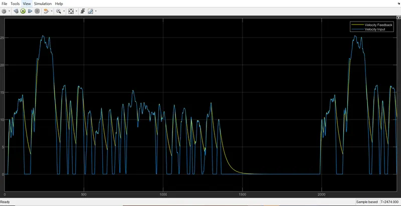
in here we can see thatthe blue colur is the initial signal which we are given and the yellow is the output signal
Looking at the graph, we can observe that both signals are nearly identical when the acceleration command is present. During deacceleration, the output almost attempted to replicate instruction. However, when a sudden brake input is applied to the model, it does not replicate the input.The quick braking input could not be recreated since it is unsafe and nearly impossible to stop a running car at a certain velocity when it collects kinetic energy and work begins.
OUTPUT CURRENT FLUCTUATION
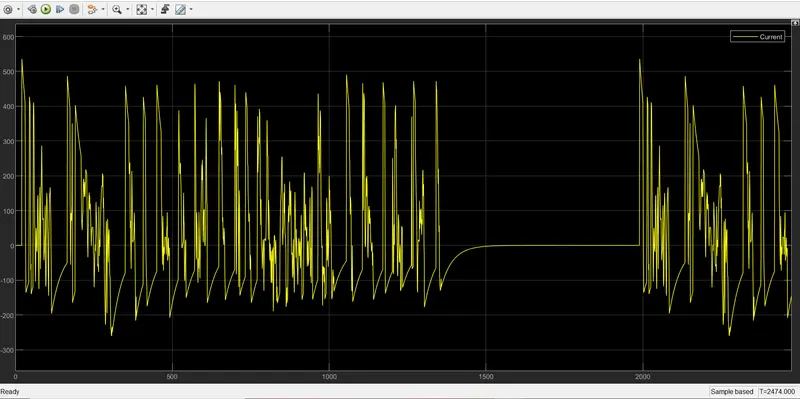
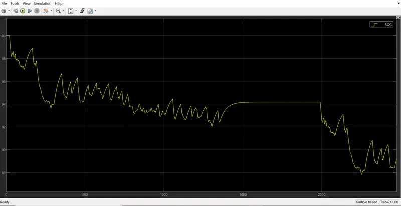
We can notice a large fluctuation during the performance, as the car undergoes acceleration, deacceleration, and braking, and for some time the car appears to be running at constant speed and at rest in the middle of the voyage as well.So, now that we've seen the velocity performance and current output, let's look at the battery performance during the journey and how much battery remains once the travel is over.We can see that more than 80% of the battery is still available for use. And as we can see from the graph, the graph is continuously lowering as the car runs. But, if we recall, we learned about regenrative braking. And if we look closely, we can observe that when deceleration or braking occurs, the battery % is always increased.As a result, it assists the vehicle in increasing efficiency and working time.
CONCLUSION:
- As a result, all of the questions are completed in according with the conditions specified and all the required files are attached