Final Project: Design of an Electric Vehicle
Create a MATLAB model of electric car which uses a battery and a DC motor. Choose suitable blocks from Powertrain block set. Prepare a report about your model including following:
Objectives:
- System level configurations
- Model parameters
- Results
- Conclusion
The MATLAB model is been created for the simulation of an electric vehicle , by assuming certain parameters and conditions while designing the model.
While developing this simulation the first of all frame of the vehicle is been modelled assuming the general parameters such as weight of the vehicle , frontal area , aerodynamic drag , rolling resistance for tires , air density etc. for this the VEHICLE BODY block is been used ,the graphical representation of block is as shown below-
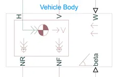
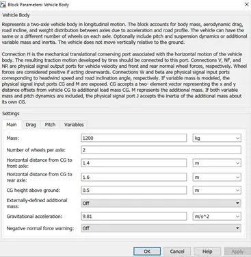
The mass of the vehicle = 12000kg
No. of wheel axle per =2
The parameters for vehicle body block are as follows-
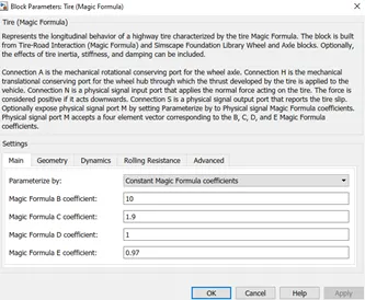
After taking the vehicle body the tires are been connected for this magical tire block is been taken , 4 such block are been used 2 for frontal tire and 2 for rear tire.
The tire parameters are been set and two tire block are been connected to NF port of the vehicle body and two are connected to the NR port of the vehicle body as they represents the front and rear axle.
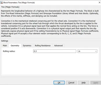
The rolling radius of all 4 tires is set as 0.3m
Tire block consists of 4 ports the are N,H,A,S
Connection A is the mechanical rotational conserving port for the wheel axle.
Connection H is the mechanical translational conserving port.
Connection N is a physical signal input port that applies the normal force acting on the tire.
Connection S is a physical signal output port that reports the tire slip.
The connection of the vehicle body related blocks are been done in following way as shown in below fig-
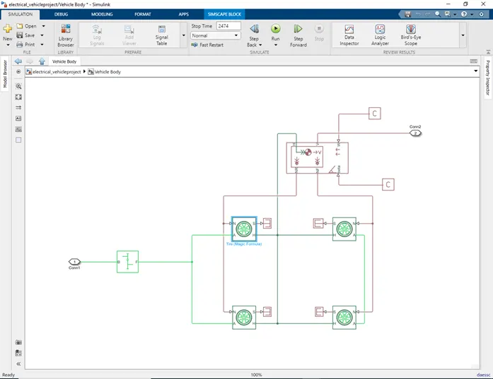
In this above format the vehicle body is been modelled , the w port of the vehicle body port is the headwind speed which is taken constant so the constant block is been connected to the w port of vehicle body as well the beta inclination is taken as zero or constant value.
A simple gear block is been connected to the front axle of the vehicle to the A port of rear tires ,so the F is the follower and B is the base of simple gear block , to the B port of the simple gear the input of DC motor are connected.
In this way the vehicle body subsystem is been modelled.
Now we will look towards the DC motor system-
A brushed DC motor is been selected , When a positive current flows from the electrical + to - ports, a positive torque acts from the mechanical C to R ports.
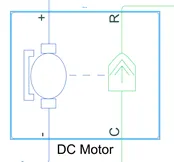
The parameters for DC motor block are-
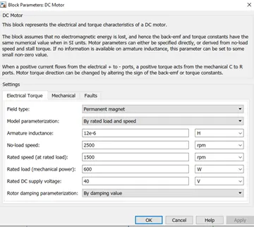
No load speed= 2500 rpm
Rated speed(at rated load)=1500 rpm
Mechanical power = 600 w
Rated Dc supply voltage= 40V
The mechanical reference and electrical reference is been connected to the negative and c port of DC motor block respectively.
After this the “+” and “-” of H- Bridge is connected to the ‘+’ and ‘-‘ of the DC motor respectively
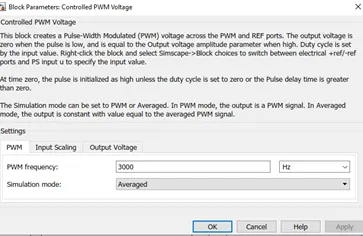
For this H-Bridge the PWM siganls are been given for this the controlled PWM voltage block is been used which gives the controlled PWM signals to H-bridge and also controlled voltage source is connected to the BRK port of H-bridge.
The parameters of H-bridge are as follows-
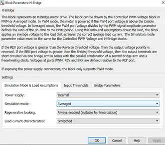
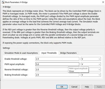
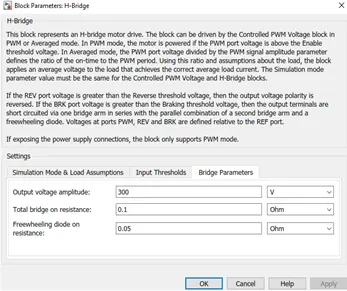
Input parameters for controlled PWM Voltage are as follows :-
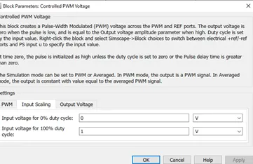
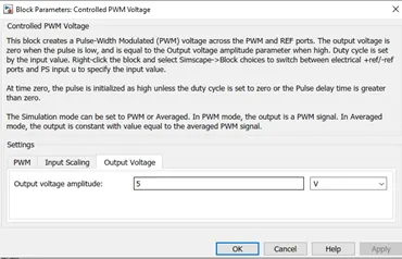
The connections for this are done as follows :-
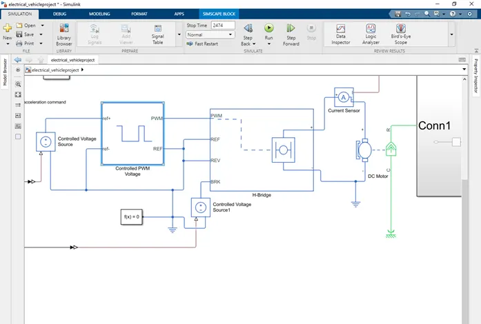
The connections for this are made like this and the circuit is been completed .
For controlling this PWM signals there must be an operator or driver which will be taking necessary actions depending upon requirement of vehicle in short there must be an controller which will look regarding all the actions to be performed.
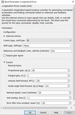
For this Longitudinal driver block is been used which will parametric longitudinal speed tracking controller for generating normalized acceleration and braking commands based on reference and feedback velocities.
Use the external actions to input signals that can disable, hold, or override the closed-loop commands determined by the block. The block uses this priority for the input commands: disable, hold, override.
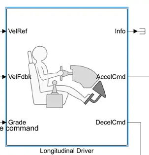
This block consists of VelRef , VelFdbk, grade command , accelCmd , DecelCmd and info ports which will take or give Vehicle reference speed command , vehicle feedback speed command , grade or inclination of vehicle and it will give out commands like accelecmd & decel command repeectively.
The parameters for longitudinal block are as follows:-
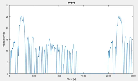
After this the driving cycle is been selected for selecting or making driving cycle command we can use multiple inputs such as driving cycle block where ready made or standard driving cycles are available , even we can use ramp signal block or signal builder block for giving the input signal for acceleration or driving pattern even we can develop our own driving cycle in excel file and use same for input.
For this input in this simulation model I have selected the driving cycle block and selected FTP75 driving cycle
The driving cycle is as shown in below graph-
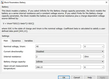
The battery parameters are as follows for an vehicle:-
The connection made for battery system are as shown below:-
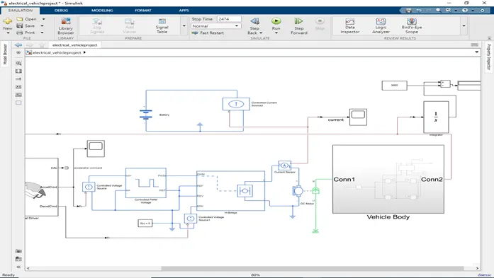
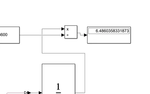
Finally the output is taken from the V port of vehicle body the speed is converted into distance by making suitable calculations. The Simulink model for that is as below-
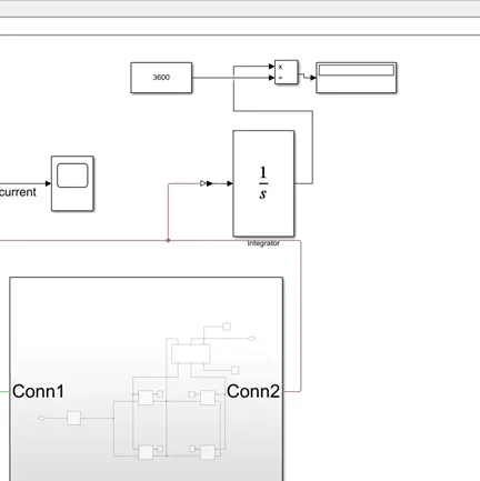
After making all the connections , the scopes are been connected at different positions for studding of the results –
Scope is used for viewing the acceleration command
Scope 1 is used to see the current drawn from the battery pack
Scope 2 is used to display the reference speed and the actual speed of the vehicle
Display block is used to see the distance travelled in kmph
Note- ps-to-simulink and Simulink-to-ps block are used where ever they are necessary for making connections.
Results:-
Scope acceleration command:-
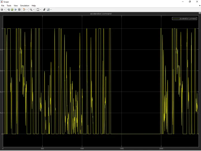
The acceleration command signals are as shown above .
Scope 1 current drawn from the battery pack:-
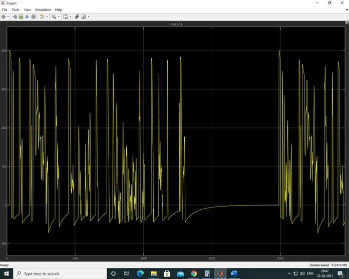
Whenever I high acceleration command is given the current drawn from the battery pack is higher. And when the vehicle is at rest condition no current is been drawn.
Scope2:-
Reference speed and the actual speed of the vehicle :-
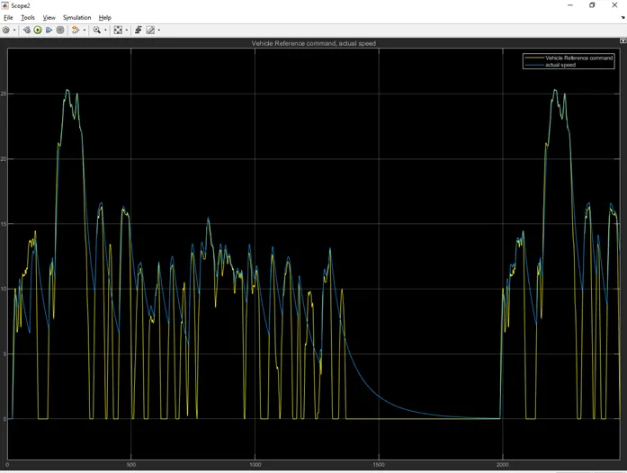
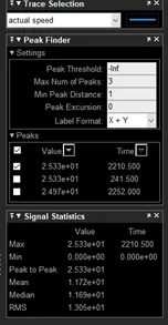
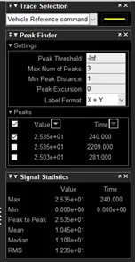
From this results its clear that the actual speed is tracing the reference speed .
From this scope we can conclude that the DC motor which we have used in suitable to achieve the required reference speed which is given as the input but the braking of the vehicle is not better and and we can not the deacceleration as per required.
Display is used to show the distance travelled by the vehicle:-
The distance travelled is near about 6.48kms